
Part 1 – Functions & Features of Advanced Hipot Testers
Introduction
Electrical safety testers – often referred to as “hipot” testers – are an integral part of electrical and electronic equipment manufacturing. Hipot testers get their name from the high potential (high voltage) they produce to perform dielectric withstand and insulation resistance tests. In addition to these tests, many hipot testers provide accurate low-resistance measurements and low-resistance/high-current outputs to test ground resistance and ground bond integrity.
Hipot testing has long been a standard procedure for assuring the electrical safety of electronic equipment. Early commercial hipot testers were actually not much more than a step-up transformer to adjust to applied voltage in stepped increases over prescribed time segments to test for leakage or component breakdown. This method could easily lead to incorrect results when leakage current caused the voltage output from a high impedance transformer source to droop. Modern hipot testers utilize electronic source technology to assure compliance with IEC-61010 that explicitly requires that “the voltage test equipment shall be able to maintain the required voltage for the specified period of time.”
Product Safety Certification
Electrical safety testing and certification is a requirement for virtually every electronic device and electrical apparatus. the details of what constitutes a certified product is dependent upon a daunting number (hundreds) of safety standards and the region of the world where the device will be sold and used. Standards setting organizations include:
- EN/IEC (European)
- UL (US)
- JEIDA/MITI (Japan)
- CCC (China)
- CSA (Canada)
Manufacturers must submit samples of their products to recognized certification agencies. Nationally Recognized Certification Laboratories (NRTLs) include UL, VDE, FM, ETL and others. The agency certification process is conducted to confirm compliance with the relevant standard(s). This compliance evaluation investigates two key areas:
1. Construction – Mechanical construction, spacing, clearances, etc.
2. Safety – To assure safe operation (even under high-stress conditions)
Work is being done to harmonize standards from global agencies. For example:
- The IEC 61800-5-1 is a safety standard specified by the International Electrotechnical Commission for adjustable-speed electrical power drive systems. It covers the safety aspects related to electrical, thermal and energy. The former UL standard (UL508C) has now been supplanted by new standard, harmonized with the IEC requirements.
- The UL document announcing this change put it this way:
“This harmonization work was undertaken with the intent of creating a standard that, while being based upon and adopting IEC requirements, would incorporate national differences that would address US installation requirements (NFPA 70, US National Electrical Code). This goal has largely been accomplished in all cases.”
To further help manufacturers address this often-bewildering array of international (and sometimes conflicting) standards, the Power Sources Manufacturers Association (PSMA) has established a standing committee and forum on its website.
Production Electrical Safety Testing
Electrical safety testing is an important final step in the production process for most electrical and electronic equipment to:
- Assure compliance safety agency labeling requirements
- Detect defective components or assembly flaws
- Reduce incidence of latent field failures and the attendant warranty costs
Once in production, products must be 100% tested to confirm with the related agency certifications and safety standards. Production tests are less stringent than initial certification but will generally include basic dielectric withstand and shock hazard (leakage) tests. Plug-connected devices will also be subjected to ground resistance and (if the standard requires) ground bond tests. Electrical motors, transformers and other such devices will likely include insulation resistance tests.
Periodic inspection and calibration of test equipment is a standard requirement to maintain NRTL certification. Agency inspection will include check of hipot instrument calibration. This “cal cert” is typically required on an annual basis. (UL and other NRTLs require compliance certification with ISO17025.) Another common requirement prescribed by most NRTLs is a daily functional test of the hipot equipment.
Dielectric Withstand – Hipot
The basic hipot test applies a high voltage from the conductors to the chassis of the device-under-test (DUT). This test is often referred to as a “dielectric” or “voltage” withstand. Its purpose is to confirm that the insulation and isolation of the non-conducting surfaces from the operating voltage is sufficient to avoid a shock hazard. The typical specification for this test ins 1000V + 2 x normal operating voltage.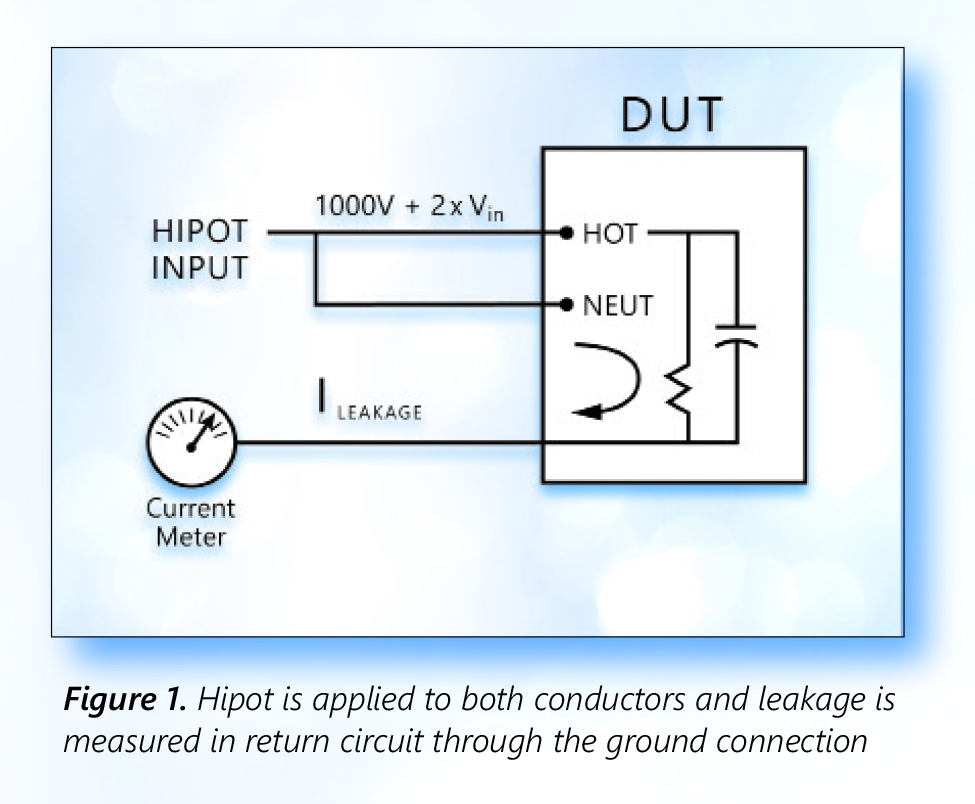
Both AC and DC hipot tests are possible and, in general, the test should use the same type of voltage as it would be during normal operation. However, if a DC hipot test is used on an AC circuit, the hipot voltage should be two times the peak (2 x 1.4 x RMS) + 1000V
Depending on the applicable standard, units pass this test if either:
- the leakage current measured is less than the maximum allowable current
- no breakdown occurs, i.e., no sudden and uncontrolled flow of current
Four double-insulated products, higher voltages will often be specified in the test standard. In addition, this class of device typically requires special fixturing to connect the non-conductive outer shell to a conductive element.
Defects that are often detected with the hipot test include contamination (dirt, debris) and lack of proper spacing (creepage and clearance) of components. Creepage is measured across surfaces, clearance is the air gap between components. Contamination would likely cause an unacceptable level of leakage current. Clearance problems could result in breakdown.
Desirable Dielectric Withstand Test Features
Adjustable maximum output voltage
- 5KV is adequate for many applications
- Higher voltage (up to 30KV) may be required
- AC and DC outputs
- Excellent regulation – both line and load
- Controllable ramp rates, dwell times and discharge features
- Phase angle measurement of leakage currrent – capacitive coupling detection
- Some standards allow for in-phase and quadrature current to be measured separately. Leakage current due to capacitive coupling may not be a safety concern
- Min/max pass/fail current limits
- Separate limits during ramp
- Programmable multi-channel testing
Insulation Resistance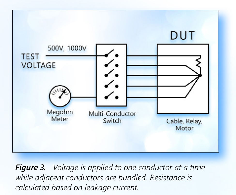
Insulation resistance testing is likely to be required in motor winding, transformer winding and other applications involving cabling or insulated wire. Insulation resistance testing typically involves confirming that the resistance exceeds a defined high resistance value.
In many instances, insulation resistance needs to be measured between several conductors. Examples include cable/connector assemblies, multi-conductor cables and relays. To make this measurement, all the conductors except one are shorted together and the test voltage is applied from the remaining conductor across the bundled ones. Each wire is then, in turn, tested in this fashion.
Desirable Insulation Resistance Test Features
- Wide range of selectable test voltages

- Accurate/repeatable high-resistance measurement
- Programmable high-voltage switching accessory
- Multi-channel programmable testing
- Pass on steady and increasing voltage
Ground Continuity
Ground continuity testing is performed to confirm that the conductive chassis of a device is safely connected to the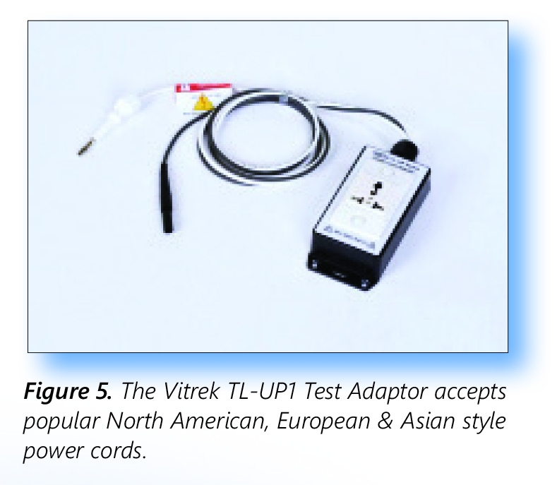 earth ground pin on the power plug. This assures protection against shock hazards even if the equipment suffers an internal short to the chassis. The current would be shunted via the ground wire and would likely trip the breaker or blow the fuse.
Ground continuity is performed by applying a low current (e.g. 50 mA) and calculating the resistance from the ground pin on the power plug to selected locations on the exposed surfaces of the DUT. Desirable ground continuity features include:
- Accurate, repeatable low resistance meter
- Plug adaptor accessory to speed testing
Vitrek’s TL-UP1 accessory is an example of an accessory device that simplifies ground continuity test setup. With its 4-foot leads, the accessory offers easy hipot and continuity test connection of corded products.
Ground Bond
Where ground continuity measures the resistance of the safety ground connection, the ground bond test assures the integrity of the connection. Using the same test setup a high current is passed through the circuit. If the ground bond is solid, the current passes without a change in resistance. If weak, the resistive heating of the current would induce a failure of the bond.
Desirable Ground Bond Test Features
- Accurate high current source
- Programmable test currents and test times
- Plug adaptor accessory to speed testing
- 4-wire milliohm meter – providing a Kelvin connection for highly accurate low resistance measurements
Part 2: Hipot Testing Safety Guidelines and Setting Up a Safe Testing Area
Introduction
Part 1 of this white paper discussed the functions and features of these high-performance instruments. The purpose of this section is to guide the hipot test user through the steps needed to make sure testing is done safely since potentially lethal voltages and currents are involved in the testing process.
Hipot Test Station Set-Up
Because there is no substitute for operator competence, the importance of having trained personnel as the first step to a safe testing environment cant be overstated. The operator should be in good health, operators with special medical conditions should not work with high voltage. All operators should understand that high voltage is dangerous, and care must be taken to avoid contact with energized circuits. They should have knowledge of the effects of electrical currents on the human body and how best to avoid shock hazards. Operators should also be taught compression-only CPR.
Operators must understand the workings and importance of safety interlocks and why the interlocks should never be disabled. They must also understand the hazards of wearing metallic jewelry around electrical equipment and show how to interrupt power quickly in emergency situations.
Other operator requirements include programming the necessary tests and storing them in memory. There should be a procedure available showing which memory location should be used for each individual device being tested. The procedure should also outline the test being performed (AC or DC, voltage, test time and limits.) The operator should use the key lock feature on the tester. This will avoid programs being changed to unknown values.
Those who train the operators should explain the object of each test, show how it should be executed and show how to handle every normal and abnormal situation that may occur. Make sure each operator understands how much he or she can handle alone and when supervisory personnel should be called in for help. They should hold regular meetings to review and update safety procedures and regulations.
Location of the Hipot Test Station
The next step is determining where the test station will be located. The test area should be isolated from the factory assembly area. It should be located away from foot traffic to assure the safety of passersby and, of course, the safety of the station operator. Operator distractions should be kept to a minimum and the area should be conspicuously marked with internationally approved signage, such as “DANGER-HIGH VOLTAGE.” During testing, the hipot tester itself should have indicator lights to denote when high voltage is present.
There should be ample and reliable power supplied to the test station. Verify that the power wiring meets electrical code requirements for polarization and grounding. Always use an outlet that has a properly connected protection ground and make sure this ground has been tested to insure a low impedance path to the panel ground and earth bonded ground. Operator injury may result if the hipot tester is not connected to earth ground properly.
The work area and bench surface should consist of non-metallic materials, which means that metal work surfaces should be avoided, and no metal objects should be placed between the operator and DUT. All other metal objects should be grounded or be out of the test area all together. An ESD mat is not a recommended platform for your test station, as it may cause erroneous readings for leakage and is unnecessary in this application. In addition, the test equipment should provide for immediate and safe removal of the output voltage using internal discharge circuitry at the conclusion of the test or if the test is interrupted. Never remove power for the hipot tester. If there is a power interruption, use extreme care in any contact with the DUT. The safest approach is to leave the DUT connected to the hipot tester until power is restored and the tester can conduct its discharge function.
Operator Safety Considerations
The test station should have sufficient space for the tester and the DUT without the operator having to reach over the DUT to access the tester. The tester should be at least three inches away from the wall to provide proper airflow for the unit. Ideally the DUT should be isolated from the operator and tester. For larger DUTs, which are wheeled to the test station, the cart should be non-conductive and having locking wheels. (This also applies if the tester needs to be wheeled to the DUT.) Keep the area clean and neat and arrange the equipment so that it is easy and safe for the operator to use.
There are many safety features that can be added to the test station to prevent the operator from encountering high voltage, such as guards or enclosures. When placed around a DUT they should be non-conducting and be equipped with safety interlocks that interrupt all high voltages when open. Interlocks should be arranged so that operators are never exposed to high voltages under any conditions.
In addition, it is easy to implement circuit palm switches that prevent the operator from encountering high voltage during testing. The basic operation of a palm switch requires the operator to use both hands to initiate a test with, potentially, a foot switch to activate the test. If one or both hands are removed while testing, the test is immediately stopped. The switches are placed directly in front of the operator and spaced shoulders-width apart. Spacing the switches prevents an operator from trying to press both buttons down with one hand or object. No high voltage can be applied to the output terminals and DUT until both switches are pressed simultaneously. The operator cannot touch the DUT or test leads if both hands are on the palm switches. The palm switches are connected to the digital I/O on the hipot tester. When the switches are in the down position the start is enabled. Once the switch goes up the safety interlock is enabled, terminating the output voltage of the hipot test. This method is safe, quick and effective.
Figure 7 illustrates two alternative approaches to setup of a bench-top hipot test. In Figure 7a, the DUT is placed on the test bench and a combination of palm switches and a foot switch ensure that the operator cannot make contact with the DUT while the test is underway. The operator is wearing safety glasses. As a practical matter, the use of palm switches is typically restricted to short-duration tests done on a repetitive basis with a series of DUTs. If this test set-up is used for longer tests, operators will find a way to defeat the palm switches.
In figure 7b, the DUT is placed under a protective cover with interlock to isolate the operator during the test. The use of an enclosure is a more reliable means to assuring operator safety, particularly when testing requires longer time periods.
More elaborate test stations can include a hipot testers interlock. One safety method that utilizes the interlock is a light curtain, which is an infrared light beam that will open the interlock if anyone interrupts any part of the beam. The output of the light curtain is connected to the interlock terminal on the hipot tester. If the interlock is open, high voltage is immediately terminated. The light curtain is placed in between the hipot tester or the DUT and the operator. For the operator to touch the high voltage they would have to pass through the light curtain, hence opening the interlock, which will terminate the high voltage.
If the hipot is placed behind the light curtain there must be a way to start the test. A foot switch is an easy solution. Keep in mind you must ensure that nobody can reach the high voltage by going around the light curtain.

Test Setup
On a regular basis, typically at the start of every shift, the tester itself should be checked by connecting the tester to both PASS and FAIL samples. These samples should be designed to confirm the proper operation of the tester based on the type(s) of tests to be conducted (hipot, insulation resistance, ground resistance and ground bond.)
Once all of the connections are made and the prescribed test procedure is selected, the operator should confirm that all test parameters, according to the test documentation, are displayed on the tester screen. Operation of the test can then be conducted, keeping in mind the safety considerations described in this article.
An appendix to this article provides a useful operator checklist for the setup and safe operation of a hipot test station.
Conclusion
Electrical safety testing is a universal requirement for electrical and electronic equipment. Testing to the specific regional requirements can be a daunting task that is simplified by the programmable features and functionality of advanced hipot testers.
NRTLs in every region of the world provide services to certify compliance with the specific standards and then regularly inspect the equipment and testing facilities used to perform production testing.
The capabilities of Vitrek’s advanced electrical safety testing equipment have been proven to be essential to efficient and accurate testing to the specific requirements of the devices under test.
Electrical safety testing, by its very nature, requires strict adherence to procedures to assure operator safety.
Appendix
Operator Checklist for Hipot Testing: Basic Safety Guidelines and Procedures
- Only properly trained operators should be allowed to use the equipment and access the test area.
- Do not make any connections to a DUT unless you have verified that the high voltage warning light is OFF.
- Never touch a DUT, the tester or the test leads.
- When connecting leads to the DUT, always connect the ground clip first.
- Never touch the metal of a high voltage probe or HV test lead directly. Only touch the insulated parts and only when no high voltage is present.
- When possible, use interlocked test fixtures only.
- Verify all DUT connections before starting a test. Make sure that no other objects are near the DUT or the tester.
- Keep the area neat and uncluttered and avoid crossing test leads.
- Suspend the test leads to minimize capacitive coupling.
- Follow the prescribed procedure for each test exactly as written.
- Verify all setup conditions before starting a test and examine all leads for signs of wear.
- Verify the tester is functioning properly by use of a performance verification device. This will also confirm the condition of the test leads. Keep the equipment on a regular calibration cycle.
- Have a “hot stick” handy when performing a DC test and use it to discharge any connection or device that may become disconnected during a test. This is necessary because unexpected, dangerous charges can build up during a test if a connection comes loose.
- At completion of a test, observe that the HV light is out. If the test was DC, the discharge may take some time.
- Ensure the tester and test station uses all the built-in safety features and functions of the hipot tester.
- Periodically test the memory to ensure consistent testing and that the parameters are not altered.
- Make sure the AC mains to the tester is properly installed with low impedance ground connections. Also make sure that the emergency switch disconnects all power from the tester and the DUT and all electrical equipment and feeds in the testing area.
- Operator and nearby co-workers should be trained in compression-only CPR in the event of a heart attack event or contact with high voltage.
Download PDF Version of this Whitepaper