Non-Destructive Testing (NDT)
Non-Destructive Testing (NDT) Customer Case This customer manufactures non-destructive test equipment which allows customers such as steel mills to test the quality of their end-products. Presently, the ultrasound frequencies being used are centered at either 5 MHz, 10 MHz or 15 MHz. The worst case analog bandwidth requirement in this case is 35 MHz. In order to set up their equipment properly, the customer presently views the return signal (including the flaw) on an analog oscilloscope with a sweep time of either 50 us or 100 us (providing approximately 5 to 10 inches of depth in a metal). The [...]

Cement Board Quality Control
Cement Board Quality Control Industrial Cement Board Quality Control Dimensions Description Introduction: Cement backer board is used as underlayment for tile floors, walls and counter tops. It is also used as exterior sheathing and in exterior stucco systems. Cement backer board has proven to be more durable than virtually any other underlayment if quality control and thickness is maintained. The Problem: A major cement board manufacturer was faced with the challenge to improve a board production line throughput and decrease the amount of waste in the process. Too thin of cement board [...]
Acoustic Micro-Imaging
Acoustic Micro-Imaging Customer Case The customer is a leader in the field of acoustic micro-imaging. They use pulse ultrasound to image non-human materials. The ultrasound frequency used is between 100 and 200 MHz, as the materials they study can handle these frequencies (one cannot normally use such high frequencies with human tissue). The customer's PRF (Pulse Repeat Frequency) is approximately 4 KHz, with a PRI (Pulse Repeat Interval) of 250 ms. They need to capture approximately 2 ms (1,000 points) of data for each pulse. The customer wants scope emulation software to allow verification of board operation without having [...]
Extruder Die Flatness
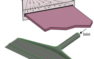
Extruder Die Flatness Industrial Extruder Die Flatness Thickness Description Introduction: Extruder dies have a flatness specification that must be maintained or the parts being extruded will be out of tolerance and non-conformant, resulting in scrap and disruptions. Periodic inspection of the die for flatness, deformation, burrs, or other irregularities is required. Situation: A tool and die company approached MTI Instruments, requesting assistance with a new method for inspecting their 20 ft long die. Contact gauges on a gantry had been the previous method; Non-contact was now the preferred practice. Solution: [...]

Water In Oil
Industrial Water In Oil Level Description
Non-Destructive Testing (NDT) Scanning Inspection
Non-Destructive Testing (NDT) Scanning Inspection Customer Case The customer is testing interior of pipes with time-resolved fluorescence, a Photo Multiplier Tube (PMT), a transducer with 8 MHz BandWidth and an integration chamber. They are searching for rare events and the scan width is approximately 3.5 inches. Multiple Record: 350 scans x 3 Kpts. GaGe Case Solution We recommended 5X-10X over sampling - therefore CompuScope 14100, CompuScope 12100, or even the 8-bit CS8500 may be sufficient. For a CS8500 Single Record example, say, at the single-channel sampling-rate of 50 MS/s, a 3000 point (i.e. 3 KS) acquisition would take about [...]
Non-Destructive Testing (NDT) of Concrete Structures
Non-Destructive Testing (NDT) of Concrete Structures Customer Case Our customer needs to perform Non Destructive Testing (NDT) to test concrete. The testing method involves using a special hammer mounted with a geophone, which serves as a transducer. They strike the concrete structure with the hammer and record the results for analysis. A definitive echo in the signal will be appear should there be a crack or a weak point in the concrete. GaGe Case Solution The customer was looking for a low-cost board that would be able to sample at 20 MHz or more, so we recommended the CompuScope [...]
Powdered Metal Level
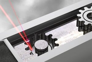
Powdered Metal Level Industrial Powdered Metal Level Level Description Many precision and no-precision metal parts are made from powdered metal. The metal may be placed in a feed ram or delivered on a web/ belt. Some processes require monitoring of the powdered metal height and it may have to be kept level across the web. For small applications a single spot laser (Microtrak 4) or several lasers may be adequate to monitor the process (powdered metal height ) and call for more metal as the ram or belt supply gets too [...]
Ice Detection
Ice Detection Industrial Ice Detection Presence/Absence Description Introduction:  Ships take in water from outside the hull to cool the engines and other auxiliary equipment. The water usually comes in through a sea chest. “The sea chest provides an intake reservoir from which piping systems draw raw water. Most sea chests are protected by removable gratings (trash screen), and contain baffle plates to dampen the effects of vessel speed or sea state. The intake size of sea chests varies from less than 10 cm² to several square meters“(Wikipedia). Problem: Frazil are [...]
Non-Destructive Testing (NDT) for Steel Manufacturing
Non-Destructive Testing (NDT) for Steel Manufacturing Customer Case The customer is a custom-built contractor of Non-Destructive Test (NDT) instruments for steel manufacturing. NDT uses ultrasonic pulses to scan through thick sheets of metals for possible causes of early wear, such as cracks or impurities. The stimulus is a stream of ultrasonic pulses. The response is their reflection from various depths. The center frequencies used by this customer are in the range of 250 KHz to 2.25 MHz and pulses are about 10 microseconds. The pulse repeat frequency (PRF) is less than 1 KHz. The thickness of steel sheets is [...]