Brake Rotors
Description
Introduction
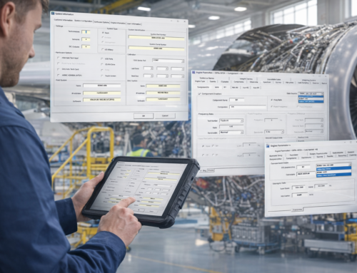
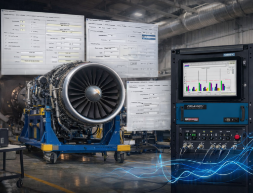
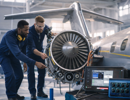
Under normal operating conditions brake rotors are subjected to extreme temperatures and forces, which can cause rotor distortion and potential failure. To make certain it can withstand these conditions; extensive laboratory testing is performed to optimize design for longevity, short stopping distance, and vibration free operation. Extensive on-vehicle testing is done under real life conditions to test prototype units and engineering designs. Test vehicles are driven for long periods of time while brake performance is monitored by a variety of sensors and data acquisition systems.
For efficiency reasons brake rotors are becoming lighter, thinner and designed with cooling vents to improve performance. These changes continue to reduce the braking surface, forcing designers to consider alternative materials and designs.
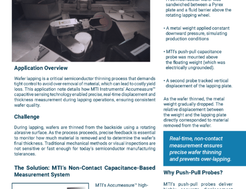
In order to simulate what a driver encounters on a daily basis, test vehicles are equipped with both displacement and temperature sensors to actively monitor the brake rotor. Data on disk runout, disk thickness variation (DTV), disk “coning” (warpage), and temperature are continuously collected and monitored from inside the vehicle. A combination of city, country and highway driving courses are set up along with many designated braking locations to fully simulate in days what a driver typically experiences in weeks or even months. This information is used so that brake designers can determine how long a braking system will operate and its overall performance.
The Problem
No brake rotor is perfect. Inconsistencies in manufacturing processes introduce thickness variation and runout so it’s important to identify these conditions prior to installation in a vehicle. In order to accomplish this, dynamic measurements of the rotor are required on the production line. Conventional non-contact capacitance displacement sensors are used to monitor the distance between the probe and the rotor while spinning. Unfortunately, rotating targets frequently have an intermittent, uncertain or nonexistent ground path which causes inaccuracies in typical capacitance sensors.

The Solution
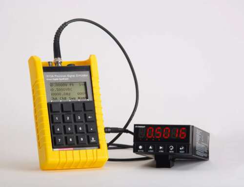
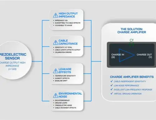
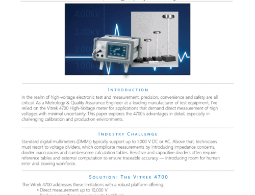
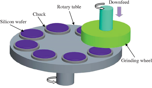
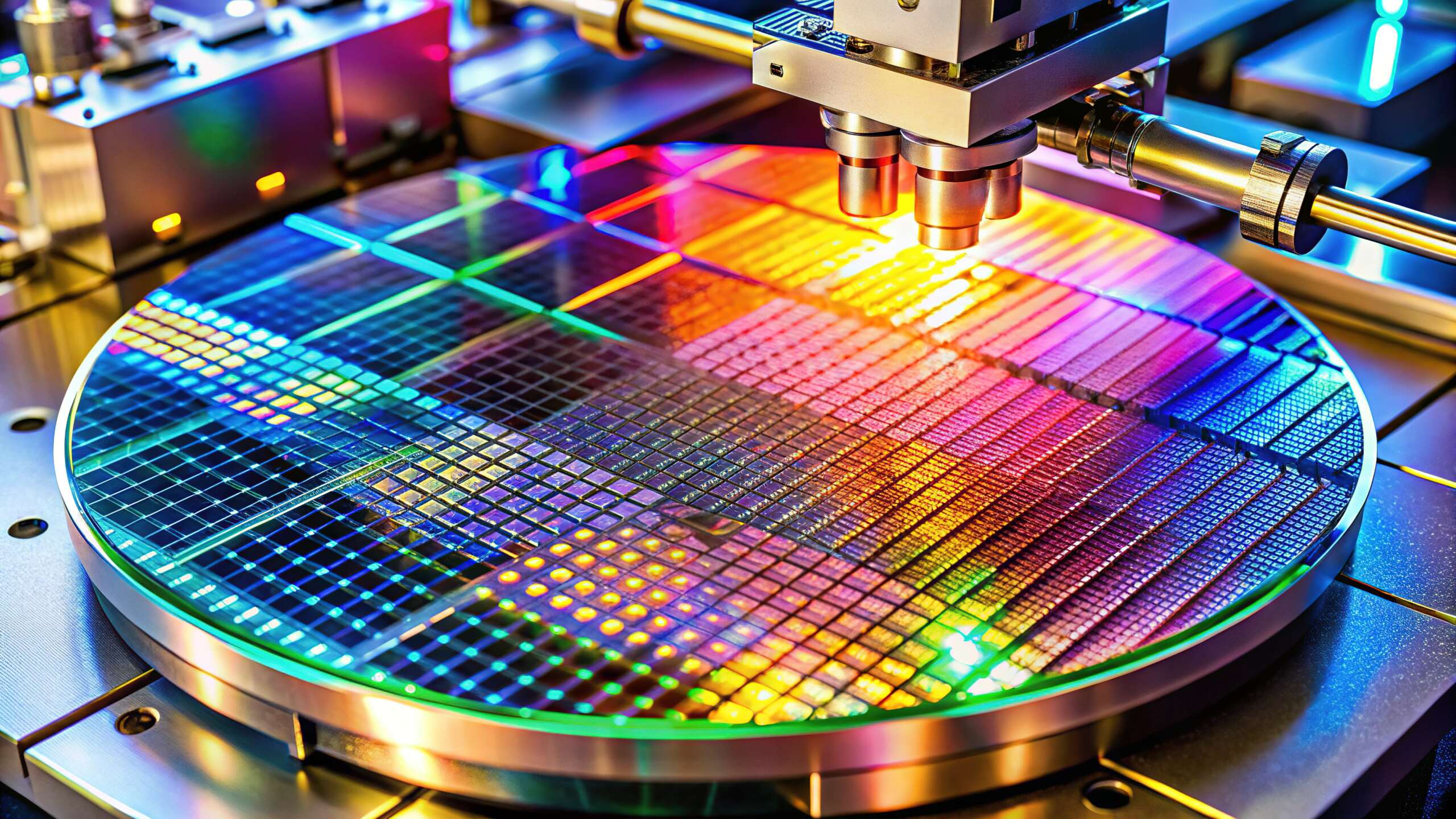
MTII offers a unique push-pull capacitance sensor which eliminates the need to electrically ground the rotor. This novel approach uses two sensing elements built into one probe body that work together to complete the measurement circuit. The push/pull probe design provides a clean and consistent electrical path resulting in decreased noise, higher accuracy and significantly more stable and repeatable measurements. Highly resistive targets can be measured with this technology allowing capacitance sensors to be used on semi-insulating and semi-conducting targets. The push/pull sensor design cancels common mode noise encountered in magnetic bearing surfaces, semiconductor wafers, brake
rotors and air bearing floating surfaces.
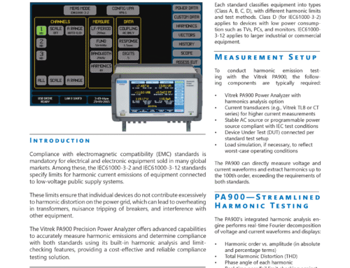
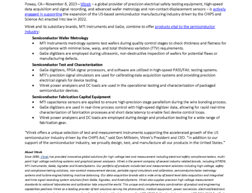
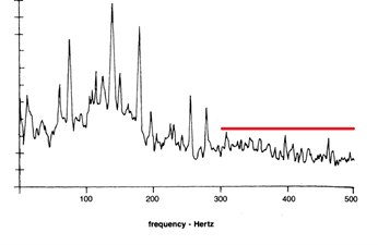
Tests were performed to compare the results of a standard capacitance probe to that of MTII’s Push/Pull technology. As the rotor was rotated, the output of each sensor was captured on an oscilloscope and is presented in Figure 3. Clearly it can be seen that the Push Pull technology provides a much cleaner and more accurate output signal.

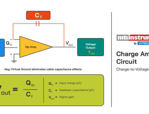
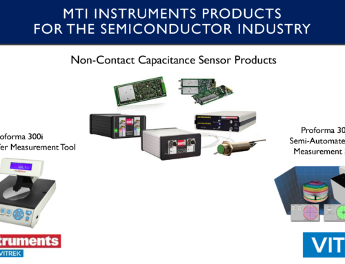
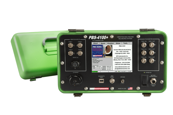
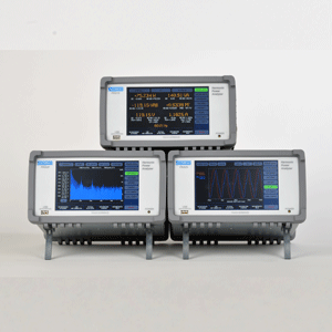
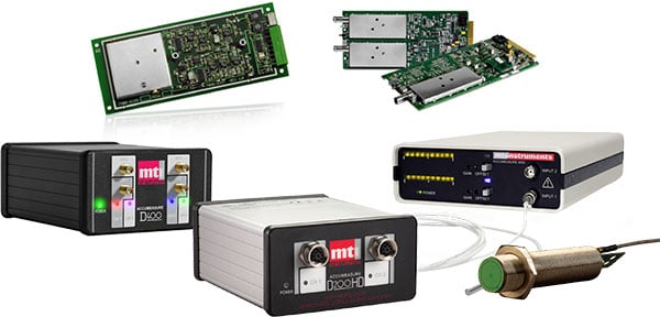
Using the Push/Pull probes with the Accumeasure™ 500 with AS 562 probe amplifier provides up to 6 independent measurement channels in a rugged, compact amplifier package. It provides the manufacturer the ability to measure thickness and or run out in 3 separate areas along the brake rotor radius ‚Äúon the fly‚Äù. The AS-500 can operate on 12 VDC power for in-vehicle testing and its compact design is ideal for installation into small, confined spaces. The amplifiers are specifically designed to be protected from shorts caused by the probe contacting the brake rotor or from contaminants such as water or oil contacting the probes.
Push Pull probes also work with the new Accumeasure™ Digital Series capacitance amplifiers which will provide increased range and digital output. Custom and high temperature probe designs are available.
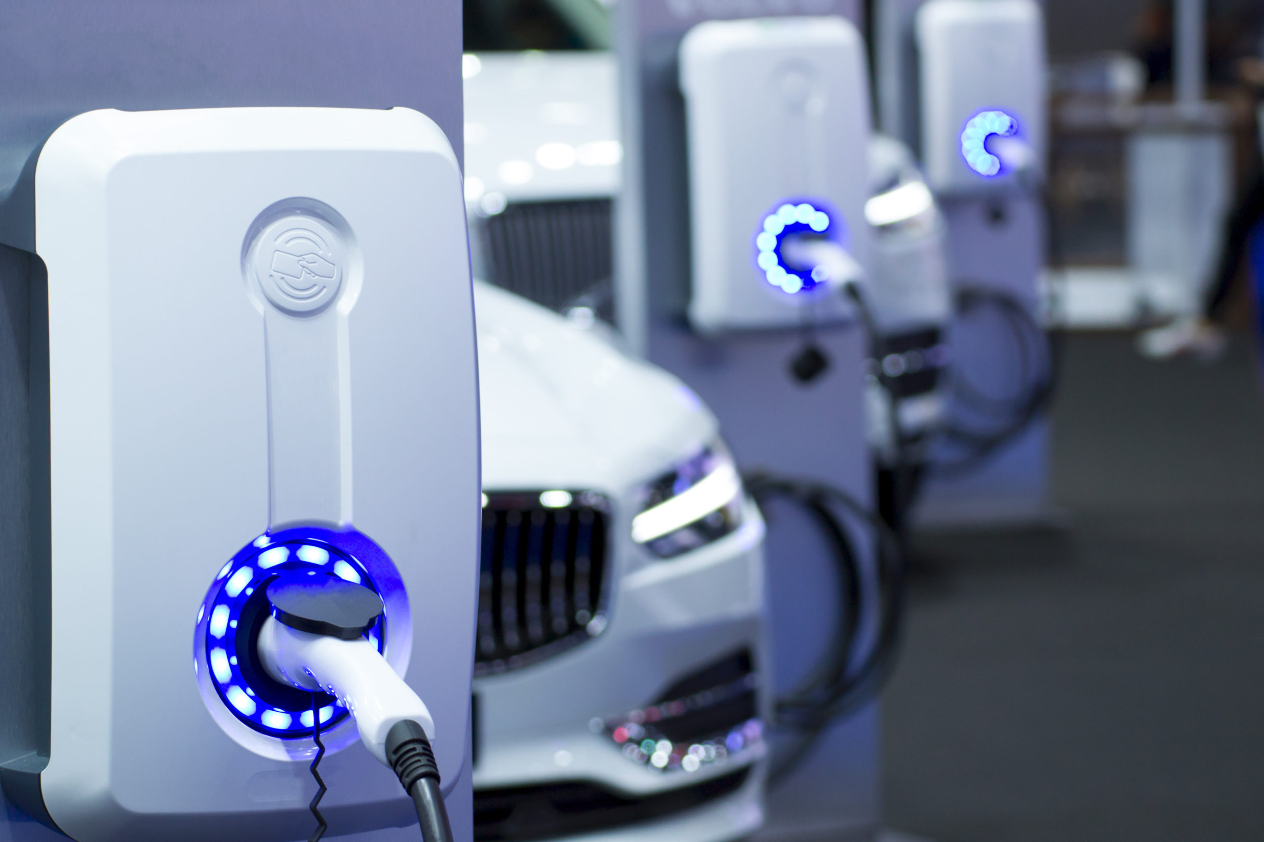
Based on the push/pull advantages, several major vehicle manufacturers have standardized on MTII’s Accumeasure sensors for their testing requirements. In addition to brake testing MTII’s sensors have been used in demanding applications such as spindle and shaft runout, engine vibration, thermal expansion and contraction, suspension travel and fuel injector motion, to name a few. If you have a challenging noncontact measurement application, MTII’s experienced Application Engineers can provide more details on laser, capacitance and fiber-optic sensors. With over 50 years of product line history MTII will provide a practical, cost effective solution to meet or exceed your requirements.


