
Capacitance Guide for Industrial Applications
This guide from MTI Instruments explains what you need to know about using electrical capacitance for
measurement in industrial applications, including advanced manufacturing.

Basic Principles
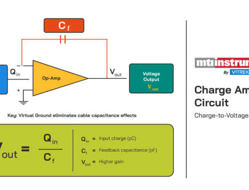
Capacitance is the ratio of the change in an electric charge to the corresponding change in its electrical potential (i.e., voltage). Capacitors, components that that have the “capacity” to store an electric charge, consist of conductive parallel plates that don’t touch or connect with each other. Instead, these metal plates are electrically-separated by air or a layer of insulating material (i.e., the dielectric).
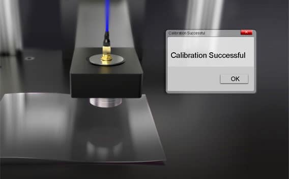
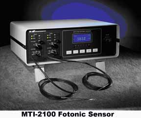
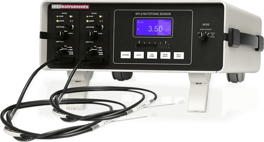
MTI’s technology is based on the principles of parallel plate capacitor measurement and uses a probe as one of the plates and a grounded target as the other. The electrical capacitance that’s formed between the probe and the target varies as a function of the distance (gap) between these two surfaces. An amplifier converts the capacitance of the gap into an output voltage that’s proportional to the gap.
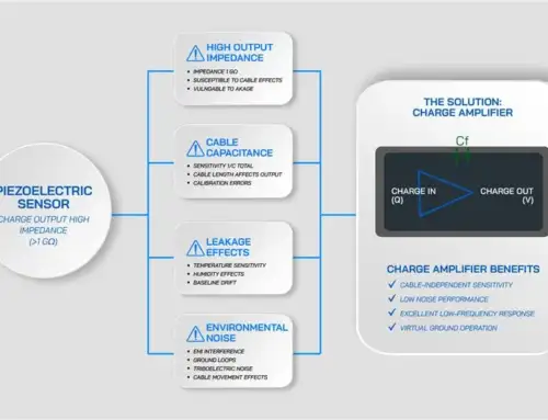
Why Capacitance?
Because capacitance doesn’t require physical contact between the sensor and the target, there’s no mechanical loading, probe or target wear, or target distortion. Capacitive probes also cost significantly less than laser interferometers while matching or exceeding them in terms of stability, precision and resolution.
Importantly, capacitive probes provide reliable performance in extreme environments. For example, they can withstand temperatures as high as 1200°F (650°C) and as low as 4°K (-269.15°C). Capacitive probes also work in very strong magnetic fields (2 Tesla) and operate under vacuum conditions (10-7 Torr). They withstand humidity, too.
Getting Started
Now that you know some basics, it’s time to examine uses and applications. You’ll also benefit by reading MTI’s case studies from different industries. Before using capacitance for your own application, however, you need to account for design considerations. Comparing the capacitance measurement systems that are available from MTI Instruments can also support your efforts.
Uses and Applications
Capacitive sensors can be divided into two categories based upon their performance and intended use. High resolution sensors are typically used in displacement and position monitoring applications where high accuracy, stability and low temperature drift are required. Quite frequently these sensors are used in process monitoring and closed-loop feedback control systems. Proximity type capacitive sensors are much less expensive and are typically used to detect the presence of a part or used in counting applications.
Standard Uses
Position Sensing
General positioning is probably the most common application for capacitive sensors. As mentioned about, the output of a capacitance sensor is proportional to the distance to the target. If the probe remains stationary any capacitance change detected by the amplifier is directly related to the target position. Their highly linear response and low output phase shift making them ideally suited to be applied in both static and active feedback positioning applications.
Other typical position applications include:
• Microscope focusing
• Lens alignment
• Part profiling
• Stress analysis
Dynamic Measurements
Non-contact sensors are ideal for measuring moving targets because they have high frequency response and do not dampen target motions by adding mass. Typical capacitive sensing systems have bandwidths exceeding 20 kHz, making them ideal for high speed applications such as:
• Spindle runout analysis
• Piezoelectric feedback positioning
• Ultrasonic horn vibration
• Stress analysis
Thickness Measurements
Thickness quality control monitoring is better applied on line during the manufacturing process instead of periodic sampling after a product has been manufactured. This way process adjustments can be made “on the fly”, reducing or eliminating the production of product that does not meet specification. In some applications, contact methods can be utilized, however, they are slow, can damage the product and are subject to wear. Non-contact sensors are commonly used in these applications.
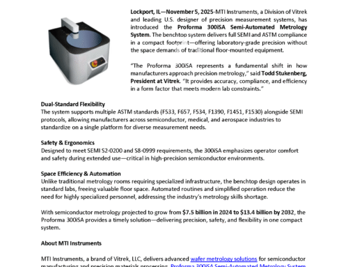
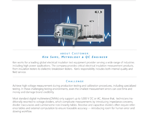
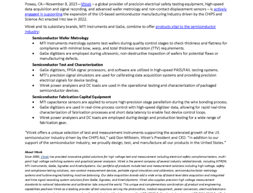
A typical application consists of two capacitance probes, one on either side of the material being measured. The difference between the output of each sensor is directly related to the thickness of the material being measured. By taking a differential measurement, any positional movement of the material within the probe gap is cancelled.
Typical thickness measurement using capacitance probes.
This is a typical thickness setup with A and B representing the sensor outputs. The gap between the probes, G, is equal to A + B + T. If an initial sample of known thickness, T, is placed within the gap, G can be determined and used in future calculations. Since thickness = G – (A + B), and G is constant, the thickness can be calculated by simply subtracting the two outputs.

Single sided thickness measurements can also be successfully made using capacitive sensors if the back side of the material being measured can be referenced to some fixed plane. The product thickness is directly proportional to the gap between the probe and the surface of the material. Typical thickness applications include:
• Semiconductor wafers
• Computer disk drive disks
• Brake rotors
• Sheet Metals
• Photovoltaic Wafers
Dielectric Material Thickness Measurements
Although MTII’s systems are primarily used to make non-contact measurements of position, displacement and vibration, they can also be used to measure the thickness of dielectric materials. When making these types of measurements a fixed gap is established between the probe face and a grounded plate. If an
insulating material is inserted in this gap the capacitance will change even if the distance between the probe face and the grounded plane remains constant. This change will create a change in the voltage output of the amplifier proportional to the dielectric thickness. Once a sensitivity factor is determined based upon the specific material being measured it is important that subsequent measurement samples have the same dielectric properties for accurate results. Several methods can be used to determine dielectric thickness as follows:
Method A
When dielectric constant of material to be measured is known:
If an Accumeasure amplifier and capacitance probe are set up at any air gap within the operating range of the system the Thickness Sensitivity Factor for a material having a particular dielectric constant can be calculated as follows:
Thickness Sensitivity Factor = Operating gap/ (VoAir- (VoAir ÷ K))
Example:
If the fixed operating gap is 0.020″ and the Vo(AIR) is 10.00 volts, and the dielectric constant K of the material to be measured is known to be 3.00, then:
Calculated Thickness Sensitivity Factor = 0.020″ /(10.00-(10.00-3.00)) = 0.003″ / Volt
Therefore, if a new sample of unknown thickness and same dielectric constant were introduced into the gap the thickness can be calculated as follows:
Test sample thickness = Thickness Sensitivity Factor x (Vo Air –Vo Sample)
For example, if the output voltage with the test sample in place reads 6.50 volts, then:
Test sample thickness = (0.003″/Volts) x (10.00 – 6.50) =0.01050″
Method B
When the dielectric constant is unknown and a sample of known thickness is unavailable If the dielectric constant is unknown or uncertain it can be measured with a capacitance system by placing a sample of the material in the operating gap and adjusting the probe until it just touches the sample. This will fill the gap between the probe and ground plane with only the material being measured. A reading of the output voltage is taken and the material carefully removed without changing the gap setting. The reading of the output voltage is taken again without the material in the gap. The dielectric constant can be calculated as follows:
K= Vo AIR/Vo Sample
After the dielectric constant is known Method A can be used to measure additional samples of the same material.
Dielectric materials are those materials which behave more like insulators than conductors. The following is a list of dielectric constant for some common plastics, rubber, glasses and liquids:

Key Advantages
- Ability to resolve measurements below one micro-inch (<25nm), at a fraction of the cost of other high performance technologies
- Most are “passive” by design allowing them to be used in extreme environments while still maintaining stability
- Sensors can be easily customized, allowing them to be adapted into a variety of applications or settings
- They are immune to target composition and work equally well on all conductive targets, unlike eddy current probes
- They are immune to ultrasonic noises, lighting conditions, humidity and temperature for the most part
Characteristics of Capacitance Sensors
Non-Contact
Capacitive displacement sensors are non-contact by design. That is, they are able to precisely measure the position or displacement of an object without touching it. Because of this the object being measured will not be distorted or damaged and target motions will not be dampened. Additionally, they can measure high frequency motions because no part of the sensor needs to stay in contact with the object, making them ideal for vibration measurements or high-speed production line applications.
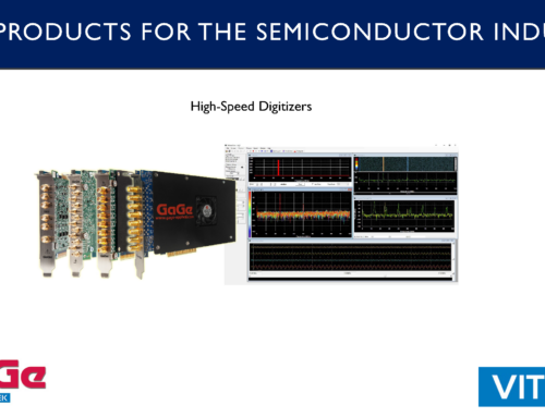
Range/Standoff Distance
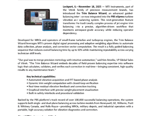
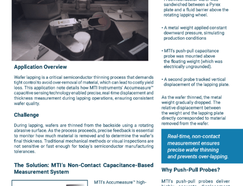
The range of a capacitance sensor is dictated by the diameter, or area, of the sensor. The larger the area, the larger the measurement range. Measurement range is typically specified starting when the probe is touching the target. At this point the output from the amplifier is zero volts. When the gap is increased to equal the full scale measurement range of the capacitive system the amplifier output is 10 volts (Vdc). In theory, the probe can operate anywhere between these two extremes, however, it is not recommended to operate below 10% of the gap. With this said, the ideal operating or standoff distance is somewhere between 5Vdc to 7Vdc which will allow the target to move closer to or further away from the probe without going out of range. Figure 3 (below) is a simplified diagram showing range, output voltage and recommended standoff for a typical capacitance sensor.
All of MTII’s Accumeasure measurement sensors have a built-in dc voltage offset. Once engaged, the output voltage can be changed by as much as 10 volts by simply adjusting a potentiometer. This is ideal if your data acquisition or monitoring system requires a -5Vdc to +5Vdc input or if it is desired to take relative measurements from some fixed voltage point.
Resolution
 The resolution of a displacement sensor is defined as the smallest amount of distance change that can be reliably measured by a specific system. Capacitance sensors offer extremely high resolution and stability often exceeding that of expensive and complex laser interferometer systems. Because of their ability to detect such small motions, they have been successfully used in many demanding measurement applications including computer disk drive runout, microscope focusing and nano-positioning within highly complex photolithography tools.
The primary factor in determining resolution is the system’s electrical noise. If the distance between the sensor and target is constant, the voltage output will still fluctuate slightly due to the “white” noise of the system. It is assumed that, without external signal processing, one cannot detect a shift in the voltage output of less than the random noise of the instrument. Because of this most resolution values are presented based on the peak-to-peak value of noise and can be represented by the following formula: Resolution = Sensitivity X Noise.
Sensitivity is simply the measurement range divided by the voltage output swing of the capacitance amplifier. From the formula, you can see that for a fixed sensitivity the resolution is solely dependent upon the noise of the system. The lower the noise, the better the resolution!
It is important to note that some manufacturers specify resolution based on peak or rms noise, resulting in claims that are 2x and 6x respectively better than peak-to-peak. Although an acceptable method, it is somewhat misleading as most users do not have the ability to decipher voltages changes less than the peak-to-peak noise value.
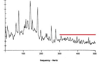
The amount of noise depends on the system bandwidth. This is because noise is generally randomly distributed over a wide range of frequencies and limiting the bandwidth with filtering will remove some of the unwanted higher frequency fluctuations. All of MTI’s Accumeasure capacitance systems have plug-in low pass filters that allow for easy adjustment in the field.

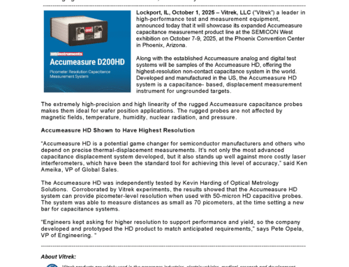
Amplifier output noise with 20kHz low pass filter

Amplifier output noise with 100Hz low pass filter
Bandwidth
The bandwidth, or cutoff frequency, of a system is typically defined as the point where the output is dampened by -3dB. This is approximately equal to an output voltage drop of 30% of the actual value. In other words, if a target is vibrating with an amplitude of 1mm at 5kHz and the bandwidth of the capacitance sensor is 5 kHz the actual sensor output would be 1mm X 70% = 0.70mm. Bandwidth curves are provided with all of MTII’s systems and can be used to correct for this dampening in high frequency applications. MTII’s applications engineers typically select a filter that has a cutoff frequency higher than the application requires to prevent any attenuation of the output. Additionally, this higher setting provides less phase shift in the capacitance sensor output allowing them to be ideally used in closed-loop feedback systems.
Push or Range Extension
Typical capacitive amplifier systems operate over a specific capacitance range, limiting their ability to measure large motions or operate at comfortable standoff distances. To overcome this problem MTII created a proprietary circuit that, with minor component modifications, can be adjusted to change the range and meet a wider variety of customer requirements. For example, a small diameter probe with a 1/2mm measurement range can be “pushed” to have a measurement range of 1mm or even 2mm. This allows MTII’s capacitive probes to be used in applications where space is limited or the target being measured is small. It is important to note, however, that a pushed probe should have a guard width sufficient enough to maintain the performance required, as mentioned above. Additionally, pushing a sensor also amplifies system noise, reducing probe resolution. Noise increase is proportional to push; 2 X Push = 2 X Noise.
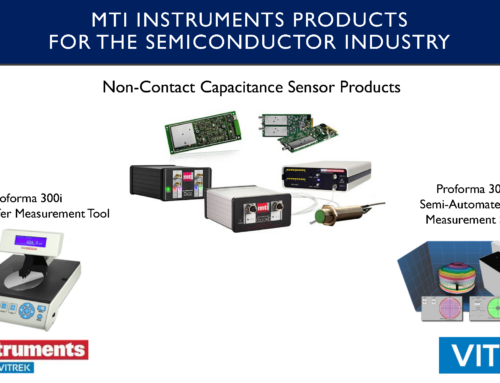
Spatial Resolution
The field established between a capacitance probe tip and measured object is typically larger than the diameter of the probe tip. This is because there is an epoxy gap between the tip and guard elements. The field diameter is equal to D plus 1x the epoxy gap. When taking measurements, capacitance probes provide a distance equal to the average surface location within the spot area. They are not capable of accurately detecting the position of features smaller than the size of the spot, however, they can repeatably measure to rough surfaces. Because of this, the probe tip should always be 25% smaller than the smallest feature you are trying to measure. Smaller sensors can distinguish smaller features on an object.

Effective Spot Size of a Capacitive Sensor
Linearity
All MTI Accumeasure capacitance sensors typically have an output of 0-10Vdc over the full scale measurement range (FSR). In an ideal world this output would be perfectly linear and not deviate from a straight line at any point. However, in reality there will be slight deviations from this line which defines the system linearity. Typically, linearity is specified as a percentage of the Full Scale Measurement range. During calibration the output from the amplifier is compared to the output of a highly precise standard and differences are noted. MTI’s Accumeasure capacitance probes offer the highest linearity available today. Most systems exceed +/-0.05% FSR with some achieving +/-0.01% or better.
Accuracy is a function of linearity, resolution, temperature stability and drift, with linearity being the majority contributor. Fortunately, the linear response of MTI’s capacitive sensors is very repeatable. Calibration reports provide data that can be used to correct for the non-linearity of a system with inexpensive computers and correction software.
Stability
Stability is a function of a variety of different internal and external factors. For short term or relative measurement applications stability is typically not an issue. However, if high accuracy is required over a long period of time care must be taken when designing fixtures, selecting components and specifying materials of construction.
Temperature is typically the biggest factor that affects stability. Temperature swings can not only cause electronic drift but it can also cause fixture and probe expansion and contraction. For critical applications MTII uses high quality capacitors, resistors and inductors specifically designed for stability to minimize the electronic affect. To minimize the mechanical affect, probes can be manufactured from special low thermal coefficient materials such as Invar and MTII’s Application Engineers can provide fixture design assistance. Thermal correction coefficients can also be provided and used for real-time compensation.
Active capacitance probe systems should never be used in high stability applications because any localized temperature change surrounding the sensor will result in drift.
Calibration
For low-end proximity sensors calibration is typically not important because linearity of the senor is not critical. Most high performance are, by design, inherently linear to approximately +/-0.2% of the full scale measurement range. Some capacitance manufacturers offer sensors with this performance, however, they are typically not suitable for high precision applications. Improved performance can be obtained by adding adjustable break point linearization within the
amplifier circuit.
During calibration the output of the amplifier verses position of a target is recorded. A best fit straight line is generated based on this data. Each recorded point is then compared to the generated straight line and the percent deviation is calculated and plotted. Based upon the results adjustments can be made to improve the deviation to within acceptable limits.
Applying Capacitance Probes
Target Material and Grounding
Capacitance measurement system mimics a parallel plate capacitor with the sensor as one plate and the target being measured the other. To create the electric field between the two plates the target must be made of a conductive material. The composition or thickness of the target is not important, allowing them to be used in many applications not suitable for eddy current type sensors. In fact, the surface can even be a few hundred ohm cm.
To complete the capacitance circuit the target should be grounded back to the amplifier. For optimal performance a conductive path is required, however, capacitive coupled targets can work well if the capacitance is 0.01 μf or higher. An example of a capacitively coupled target is a shaft rotating on air bearings. In theory, air bearings are non-contact but the gap between elements is small, and their area is relatively large, creating a high capacitance path. Thousands of successful applications world wide have been installed with this type of ground.
If the target is poorly grounded, the system is susceptible to external noise and interference. Care should be taken when designing the ground return path. If a ground is not possible MTII’s Push/Pull capacitance probes are an excellent alternative. Section ix provides more information about these unique capacitance sensors.
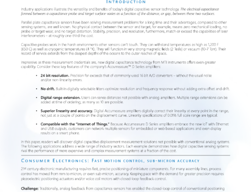
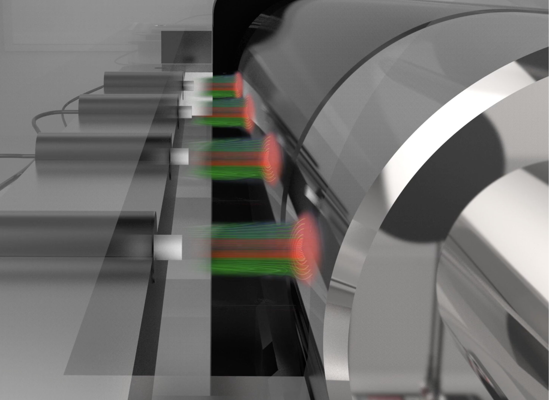
Target Size
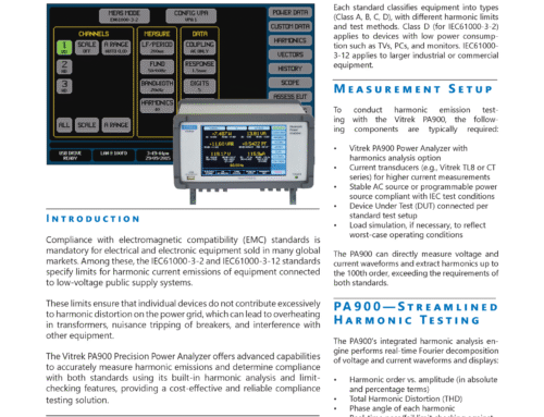
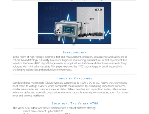
The lines of flux in the electric field established between the probe and target always leave the capacitance sensor normal (90 degrees) to its surface and always enter the target normal to its surface (see Figure 2). If the target being measured is large enough, and the sensor is within range, the field within the sensing area will be consistent and linear. If the target is not large enough to support the field it will tend to wrap around the edge and enter normal to the target side. This field distortion will create measurement errors by degrading the sensor linearity and changing its measurement range Because of this the original factory calibration can no longer be used and an in-place calibration is required, however, accuracy may still be compromised.
Targets that are too small to support the electric field can also provide false displacement signals from lateral motions. Capacitive sensors are typically used to measure the gap or movement in the direction of the sensor axis. If the target is large enough any lateral motion will not distort the electric field, however, if the field is wrapped around the target any lateral motion will change the shape of the field causing a change in output even if the gap remains constant. As a general rule, the target should be 30-50% larger than the capacitance sensor.

Field Distortion from an Insufficient Target Size
Target Shape
Capacitance probes will measure the average distance to the target under the area of the sensor. If a tilted or curved target is being measured the electric field will be distorted and the accuracy compromised. When sensors are calibrated to a flat target the output voltage is theoretically zero when the probe is in contact with the target. This is not true when measuring curved or tilted surfaces because the surface prevents the probe from full target contact. The result will be a shift in the zero point from its original calibration atMTII, which will show as an offset in the measurement, not a sensitivity change. To overcome both issues an in place calibration is possible to correct for the sensitivity change, however, the sensor measurement range may be reduced. MTII can perform a customized calibration if the application conditions can be duplicated in our laboratory. As a general rule, a curved target should be 10 times larger in diameter than the
sensing element of the capacitance sensor.
Spatial Resolution
Capacitance sensors have a relatively large sensing area in relationship to their measurement range. As mentioned above, these types of sensors take an average measurement to the surface in question. If this surface has features that are smaller than the sensing element the feature may not be detected or the sensor output may not respond accordingly. The probe size can affect the sensor output when looking at a stepped object. The sharper voltage changes from the smaller diameter sensor.
Similarly, the output will depend on the surface roughness. If the roughness changes over an area the output from the capacitance sensor will change when the target translates beneath the probe because the average distance to the surface has changed. The amount of sensor output shift will depend on the magnitude of the surface roughness.
Environmental Conditions
Capacitance changes as the distance to the target changes. The capacitance also depends upon the dielectric property of the material in the gap. Because of this, it is important that there is a homogeneous, non-conductive material between the probe and target. In most applications, this material is air, however, many times oil or some other dielectric fluid is successfully used. If it is not homogeneous, or if the dielectric properties in the gap change, then accuracy will be affected. This is typically not a problem for changing air properties because the effects are small. For instance, the dielectric constant of air changes by approximately 1.4 ppm/% relative humidity. This represents a potential offset in the senor output of less than 1 mV with a relative humidity change of 50%. Care must be taken to avoid dielectric changes from other materials and ensure dirt and debris do not accumulate in the capacitive probe gap.
The most common environmental problem that can affect the accuracy of a capacitive sensor is temperature. Not only do the electronics exhibit temperature drift but also expansion and contraction of the probe and fixturing physically changes the probe gap. All of MTI’s Accumeasure amplifiers have a temperature stability of less than +/-0.1% of the full scale measurement range over a temperature change of 40ºF to 104ºF (4ºC to 40ºC). MTI’s standard capacitive sensors are made of stainless steel which exhibits a thermal coefficient of expansion of less than 200ppm/degree C. Custom probes manufactured of highly stable materials, such as Invar, are available for extreme stability applications. It is also possible for engineering to adjust the temperature coefficient of components for custom high stability applications. MTI also manufactures high temperature probes capable of operating above 500ºC.
Fixturing
It is important that the fixture holding a capacitance sensor is stable. Temperature changes can cause expansion and contraction resulting in a distance change to the target. Fixtures should be made of the appropriate material to minimize this effect. The fixture supports should also be as short as possible and long cantilevers should be avoided to minimize not only temperature issues but to also reduce vibration.
Most capacitance sensors are cylindrical and can be secured using epoxy, set screws or “Vee” blocks. Each method is accept able, however, care must be taken to ensure the capacitive probe is perpendicular to the target and not able to move. For best performance, it is also recommended to ground the outer body of the probe so the fixture should ideally be electrically grounded. In addition, mounting the capacitance sensor as close as possible to the sensing face will minimize expansion and contraction errors. Probes of other shapes are available and MTII can provide custom flanges or mounting designs.
Synchronization
If more than one measurement is required on a single target the amplifiers should be synchronized to reduce possible interference. Synchronization is accomplished by making sure the oscillators that drive the electronics are in phase. When out of phase, “beat” frequencies may be seen on the sensor outputs. This is not a problem when the number of measurement points can be satisfied with one chassis (such as the dual channel Accumeasure 9000 or the multi-channel systems: Accumeasure 1500 or Accumeasure 500) because all capacitance amplifiers are driven by the same oscillator. If more than one chassis is required, one chassis should act as a master, causing the others to be synchronized “slaves”. MTI’s Accumeasure line of sensors has provisions to configure any amplifier as a master or a slave.
Cable
The “guard” that surrounds the electric field as it leaves the sensor is of high importance. In addition to improving linearity and accuracy, the guard is also used to reduce noise and external interference. Each capacitance probe is driven by a coaxial cable. The shield of the cable is used to deliver the voltage to the guard, and you may recall at the same potential and phase as the sensor signal. This eliminates any stray capacitance that might be created between the center conductor and the shield of the cable, or any other part that may be close to the cable. By design it not only reduces the capacitance load on the amplifier but it also keeps it constant so any change seen by the amplifier is related only to a probe gap change. It is important to note that ordinary coaxial cable will not provide adequate protection and special cable is required.
Typical capacitance probes have cable lengths of approximately 8 feet (2.4 meters). Adding additional cable is common, however, noise will increase. In general, each additional foot of cable will add approximately 0.05mV of noise when using a specially treated low noise 30pf/ft cable. Additional cable will also add capacitance load on the sensor amplifier so cable length should be carefully considered.
Push/Pull Technology
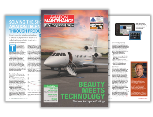
For best performance, standard capacitive sensors require the target to be electrically grounded. Current flows from the probe face to the target and back to the amplifier to complete the circuit. The capacitance created is monitored and related to the probe gap. The measurement of electrically grounded targets can be, however, affected by changes in the electrical conductivity or ground path of the target. To eliminate the effects of these variations, MTII developed a unique version of the Accumeasure sensor called the push-pull. In this design each probe consists of two capacitance sensors, built into one probe body.
Each sensor is driven at the same voltage, however, there is a 180 degree phase shift between signals. This shift allows the current path to travel across the target surface rather than through the target to ground, eliminating any inaccuracies created by poorly grounded targets. Additionally, highly resistive targets can be measured with this technology allowing capacitance sensors to be used on semi-insulating and semi-conducting targets.

MTI’s Push/Pull Capacitance Sensor
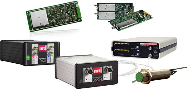
Products for Capacitance-Based Measurement
| Capacitance Displacement and Gap Measurement Probes |
Accumeasure OEM Boards | Digital Accumeasure |
|---|---|---|
 |
 |
 |
| Accumeasure Modular Capacitance Rack System |
Accumeasure Analog Capacitance System | |
 |
 |
Advanced Uses
Position Sensing
- Supports closed-loop feedback systems for micron and sub-micron precision.
- Piezo motors support high precision but are less accurate with open-loop linear response.
- Capacitance eliminates mechanical loading becausethere’s no physical contact.
Dynamic Measurements
- Real-time data instead of data logging.
- Frequency and amplitude measurements with component vibrations.
- Measuring thermal expansion across heating and cooling cycles.
Thickness Measurements
- Capacitance changes when an insulating material is inserted into the gap.
- This change occurs even if the distance between the probe and target remains constant.
- The amplifier’s voltage output changes and is proportional to the dielectric’s thickness.
Industries & Case Studies
Capacitance is used in industries ranging from aircraft maintenance to tire manufacturing. As the following case studies explain, capacitance is also used in consumer electronics and semiconductor manufacturing, wind and solar power, industrial processing, and in the automotive industry.
Consumer Electronics
Electronic manufacturing requires the fast, precise positioning of miniature components. On many assembly lines, process control now demands micron or even sub-micron accuracy. For precision positioning with piezoelectric actuators or voice coil motors, digital capacitance sensor systems combine closed-loop feedback with speed and accuracy.
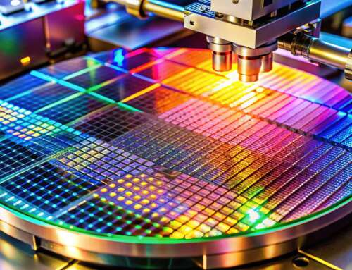
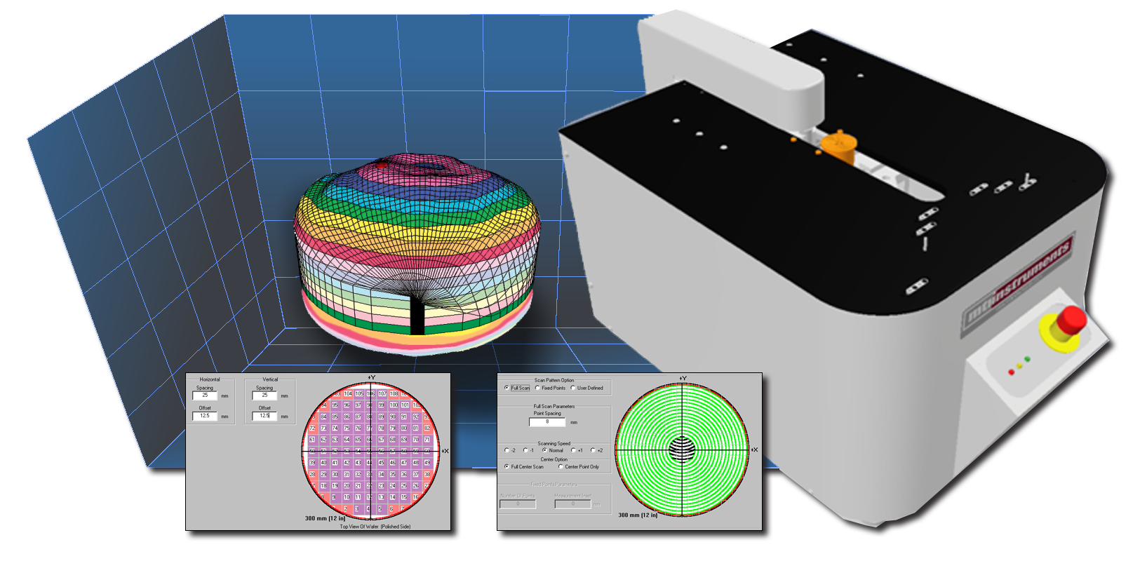
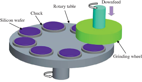
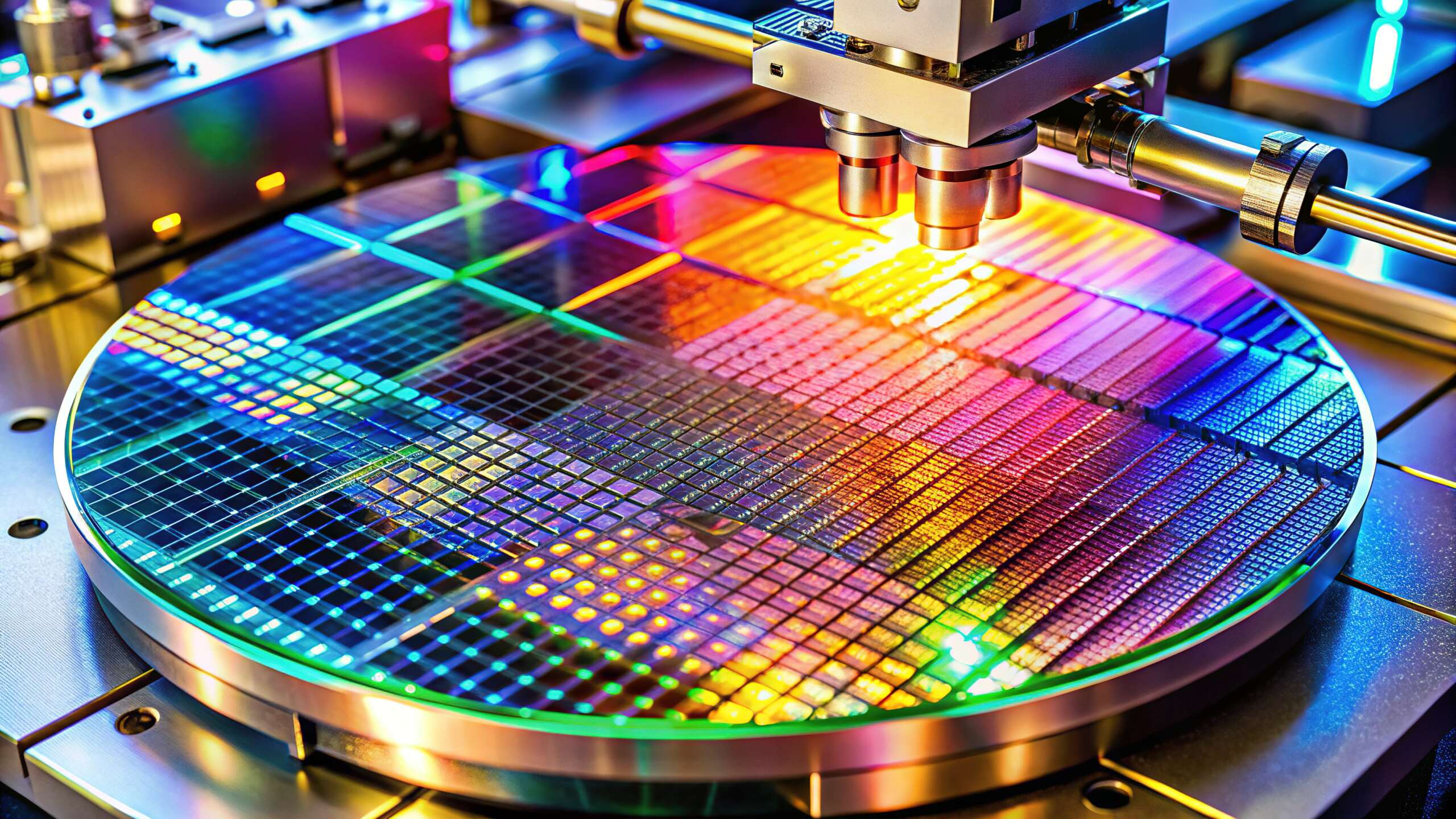
Semiconductor Manufacturing
Semiconductor manufacturers are building three-dimensional (3D) integrate circuits (ICs) that feature vertically-stacked silicone wafers and dies. This helps boost device performance, but 3D ICs need coplanar surfaces that make contact with all pins, pads and pillars. To achieve high-resolution position control, capacitance probes are used. The gap measurements are processed with a high-precision digital amplifier.
Power Generation
The power generators for wind turbines need an optimal gap to ensure peak efficiency. They also need a gap measurement solution that withstands harsh environments and magnetic fields. Corrosion-resistant capacitance probes made of non-magnetic materials are durable and highly-precise. They integrate with
digital amplifiers and support the use of custom cables that prevent magnetically-induced currents.
Solar Technology
The solar industry needs higher-density chips with smaller critical dimensions. Capacitance enables precise measurements, but grounding can damage wafers or interfere with sensing. Pull capacitance systems that measure ungrounded semiconductor wafers remove these risks. They also eliminate inaccuracies by supporting poorly-grounded targets with sub-micron precision.
Automotive
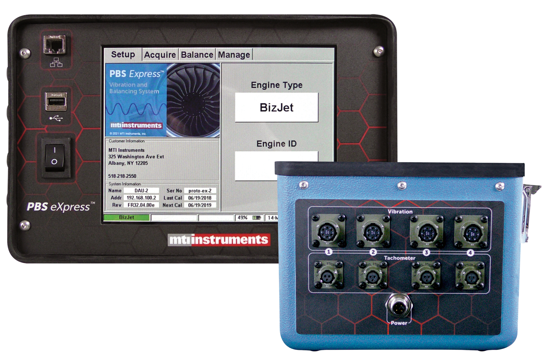
Brake rotors are now thinner and lighter, but they’re still exposed to conditions that can cause distortion or failure. That’s why the automotive industry needs continuous data collection during testing. Multi-channel measurement systems that withstand high temperatures and provide 24-bit digital readings eliminate errors from analog filtering, linearization, range extension, and the summing of channels.
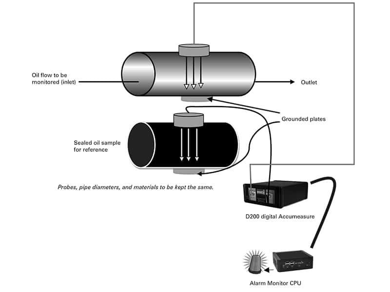
Industrial Processing-Oil System Contamination
Water-in-oil contamination can reduce the life of industrial lubricants and increase the cost and frequency of repairs. In-line capacitance probes support a proactive approach to maintenance and, when used with a digital amplifier, can trigger a CPU alarm if the dielectric field reading for an oil flow channel
differs from the reading for a sealed oil sample. Monitoring is both continuous and automatic.
Design Considerations
Before using capacitance with your application, you’ll need to ask and answer a series of questions:
• What are you trying to measure?
• What is the level of accuracy that you need?
• What is the application environment?
• What are the risks of grounding the target?
• Do you need continuous, automatic monitoring?
This is just some of what you’ll need to know. That’s why it’s important to choose the right partner, too. To learn more about MTI Instruments products visit www.Vitrek.com, e-mail MTIsales@Vitrek.com or call (800) 342-2203.


