Signal Generator Simulates Eddy Current Probe
Description
[Application Note 31218]
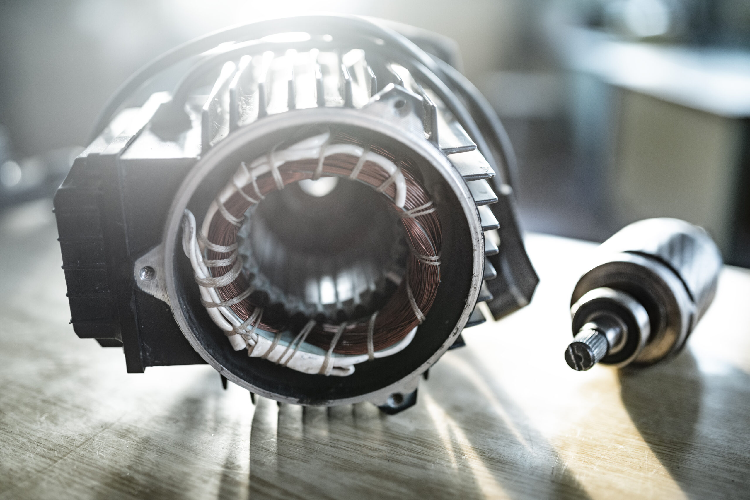
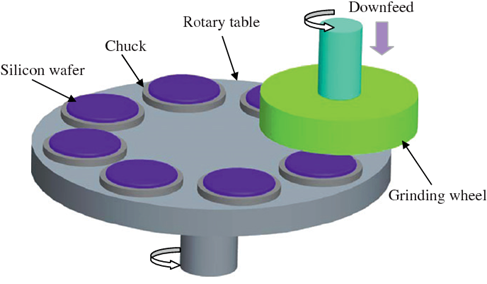
Non-contact eddy current probes can be used to measure the position, or position change, of conductive targets in real time. Typical monitoring applications include shaft runout and/or vibration.
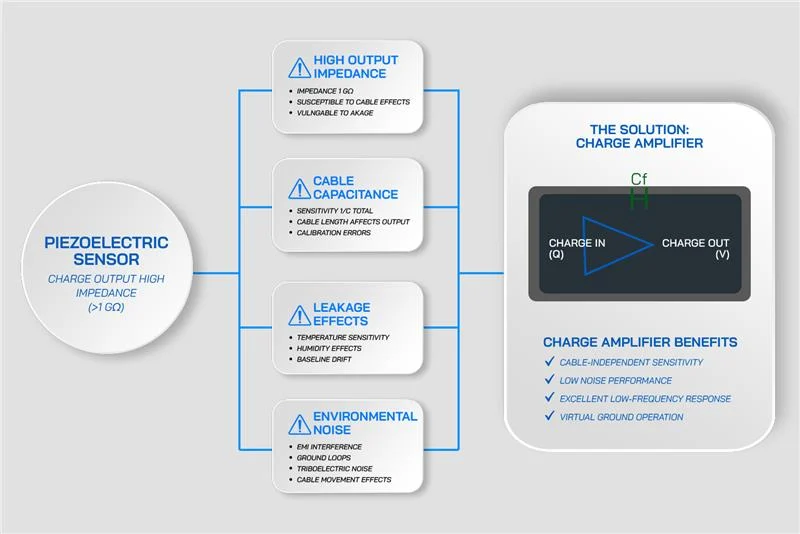
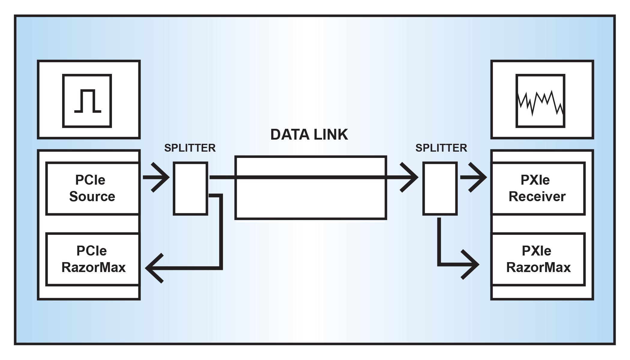
Probe setup requires an oscillator demodulator circuit. This circuit converts the probe’s magnetic field readings into output voltages proportional to the gap between probe and target. Portal signal conditioning electronics are then used to amplify, filter, and digitize the signals.

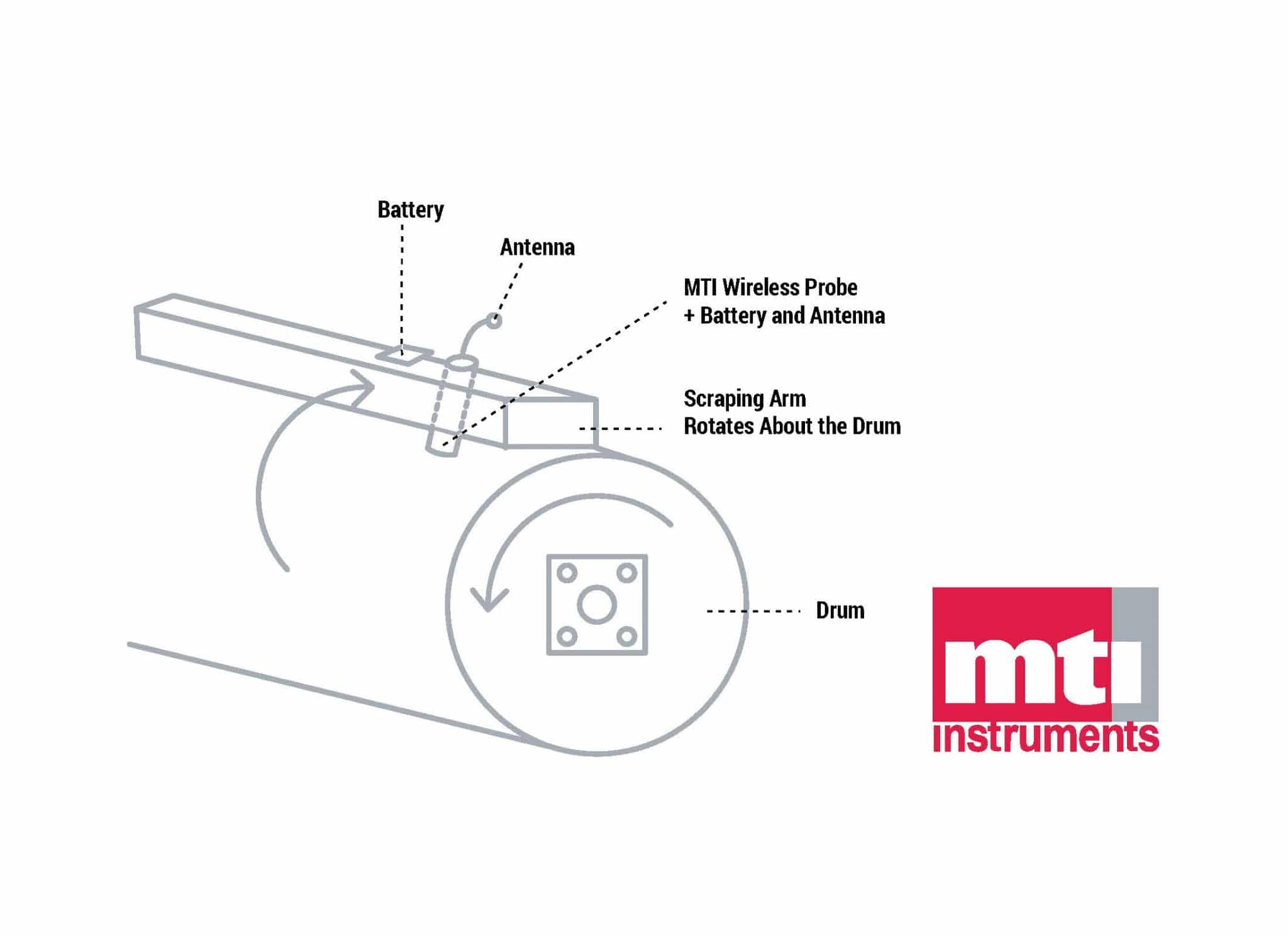
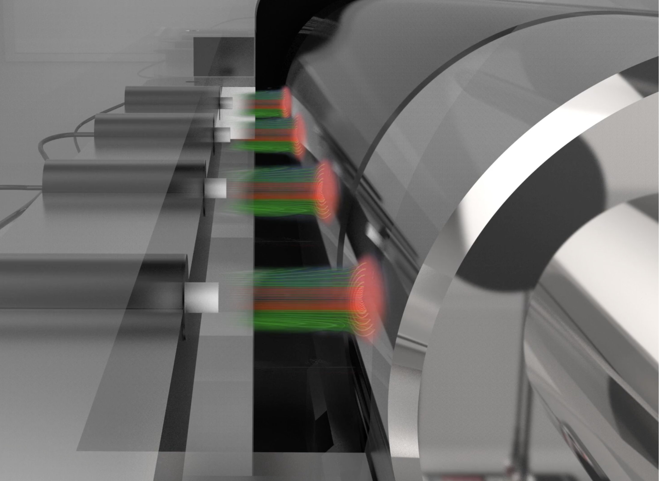
Eddy current probes are often used to monitor shaft runout and vibration. An alternating magnetic field, generated by the sensing coil, induces eddy currents in the target. These create an opposing magnetic field, producing a voltage output proportional to the distance between probe and target.
Problem
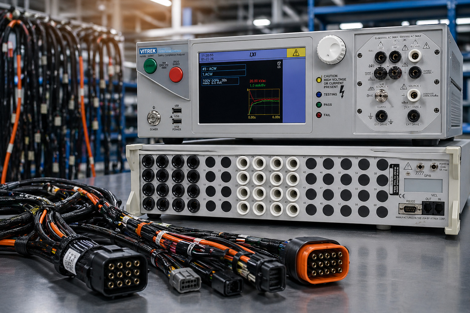
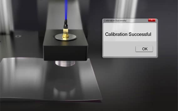
To ensure probe accuracy, and to verify the machinery being monitored is operating within specified tolerances, it is important to calibrate the signal conditioner electronics connected to the eddy current probe.
Solution
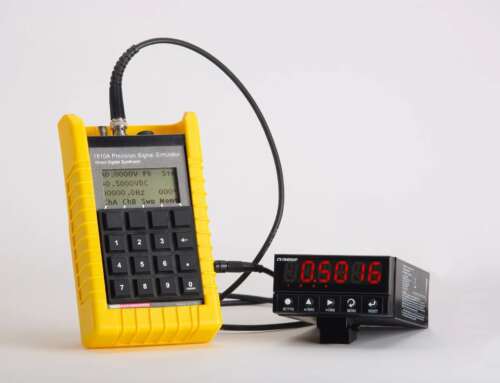
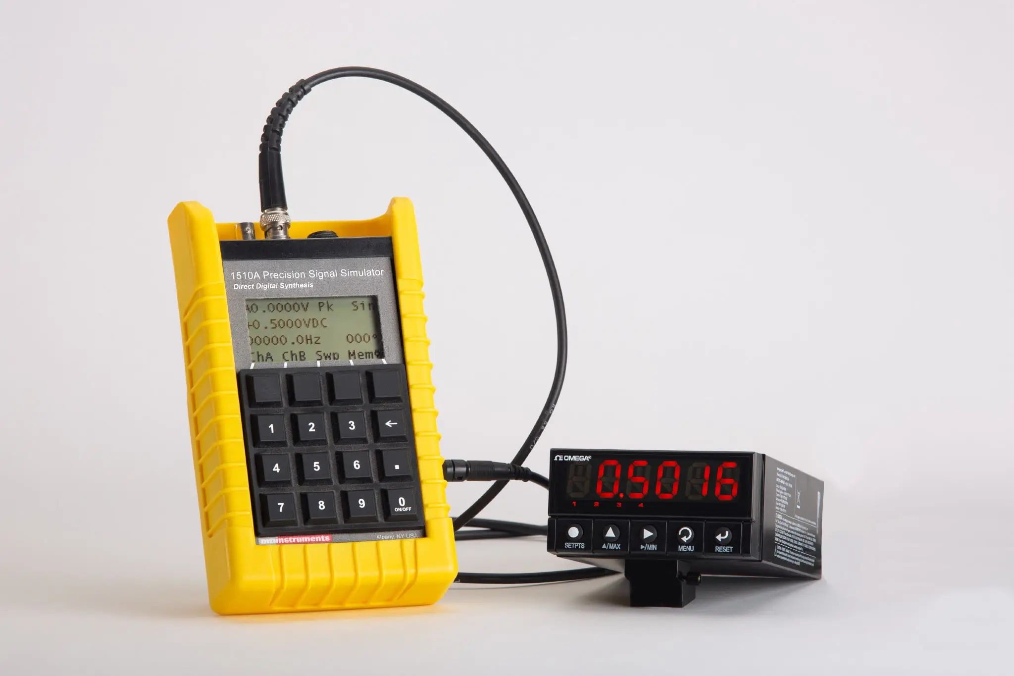
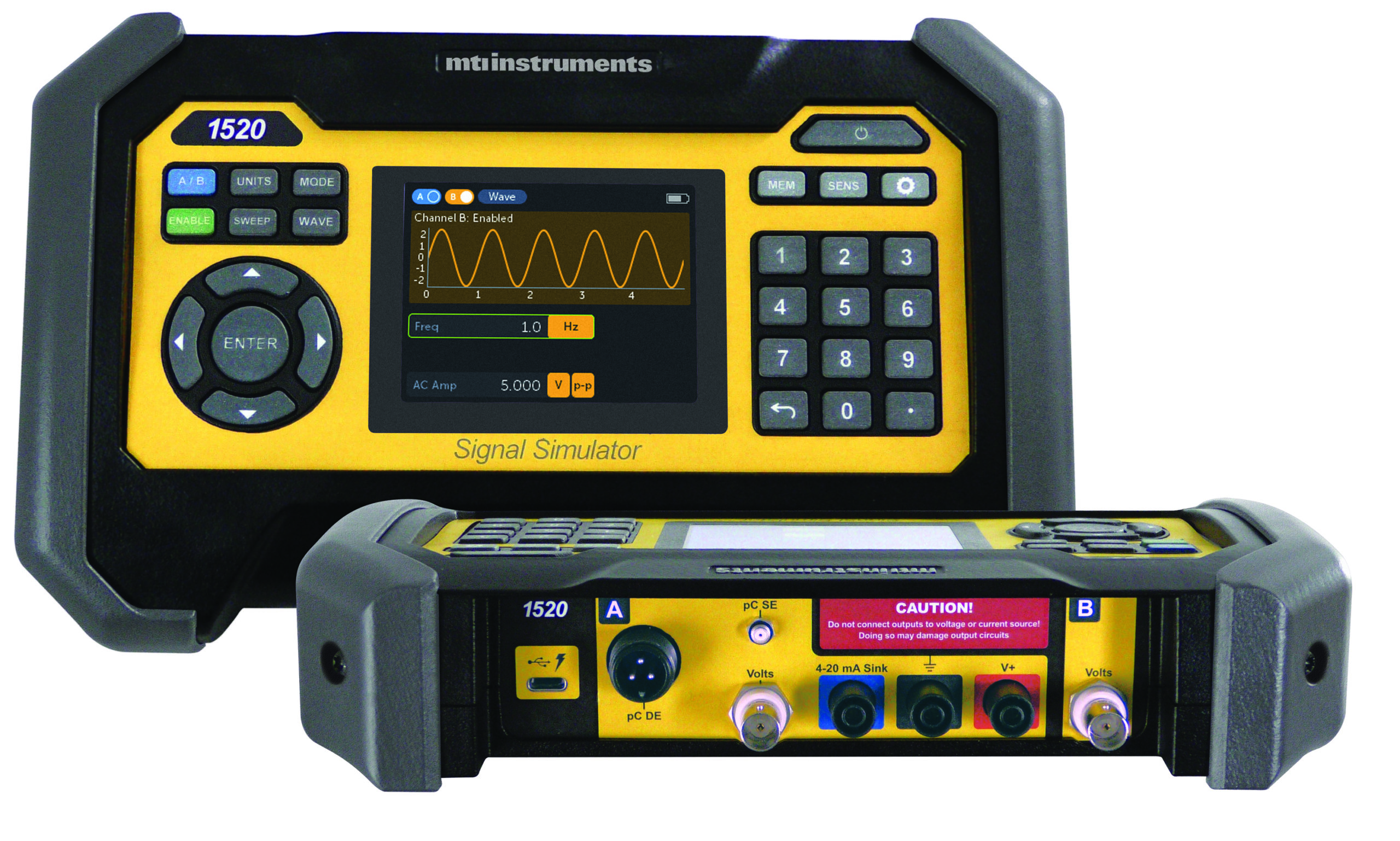
Use MTI’s 1510A portable signal generator to calibrate conditioning electronics. First step: temporarily swap the eddy current probe demodulator output with MTI’s 1510A portable signal generator. Next, select a typical probe gap DC voltage (refer to 1510A Operation and Maintenance Manual, page 8 for DC amplitude), pick a frequency such as 500 Hz (manual, page 10), and increase the AC signal modulation until the signal conditioning electronics indicate an alarm condition (manual, page 8). This procedure verifies the monitoring system is working correctly.

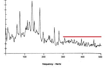
Users can also vary the simulated vibration frequency to check filter set points in the signal conditioning electronics. This step ensures that high or low-frequency vibration signals can be detected. Lastly, vary the DC and AC voltage amplitudes to check alarm set points.
Benefits
Unlike competing products, the 1510A can accurately generate precision low voltages without drifting. In addition, the 1510A self-monitors its output using feedback to adjust output voltage and hold it at the correct value.

Non-contact eddy current probes can be used to measure the position, or position change, of conductive targets in real time.

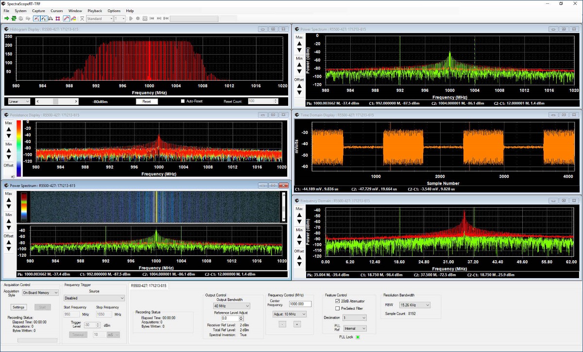
Eddy current probes have a voltage offset and produce a sinusoidal signal in a typical shaft run out application. The offset is proportional to the probe gap and can be either positive or negative.


