
How to Achieve <1um Accuracy When Measuring Roller Gap
Roller Gap Measurement with MTI Digital Accumeasure Capacitive Probes
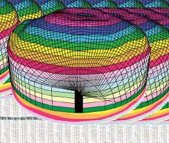
Many roll-to-roll finishing processes typically use a calender, or series of hard pressure rollers, to deliver smooth, high-quality products of plastic, textile, or paper (Fig 1). Ensuring a consistent material thickness, however, depends on the ability to monitor, and maintain, a precise gap between rollers. This application note describes a quick and easy means for roller gap measurement.

Problem
How to measure the small gap between rollers to keep track of product thickness. Typically, it’s not possible to insert sensors in the thin gap because most sensors are too large, or the gap is too hot and dirty.
Solution
Machine a relief cut ~25 mm in from the roller edge that allows the placement of thin capacitive sensors that can monitor the roller gap by adding a step offset equal to the fillet relief cut. The relief cut only needs to be ~1 mm deep by perhaps 25 mm horizontal from the roller edge. Measuring the relief cut gap gives a direct measurable reference to the roller gap (gap + an offset).


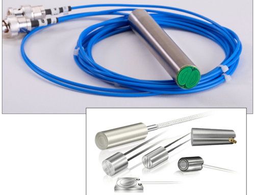
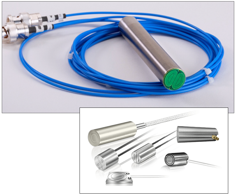
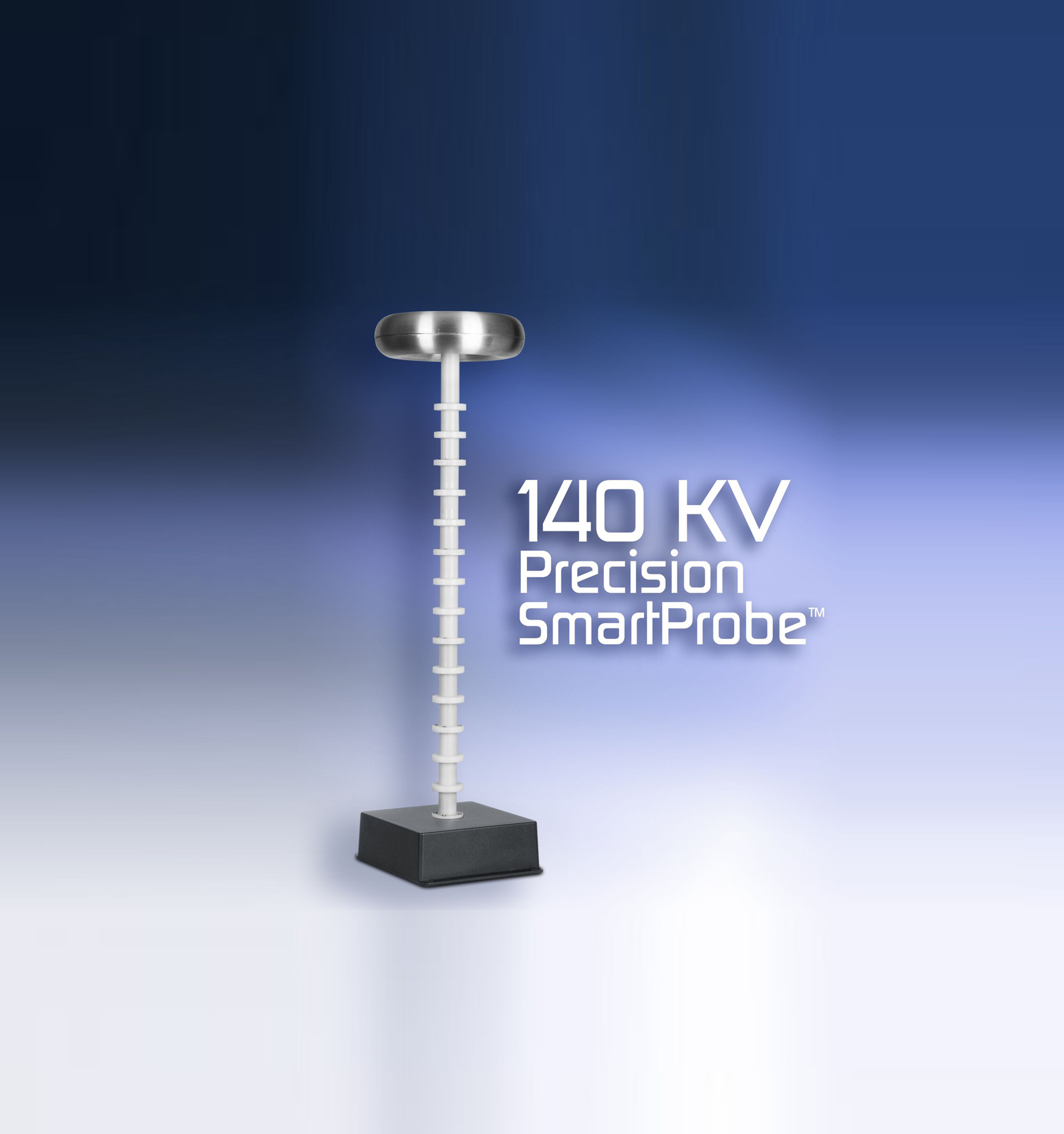
Figure 4. View of capacitance probe sensing area. It has two sensors, one looking up, the other looking down to simultaneously measure the whole gap.
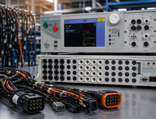
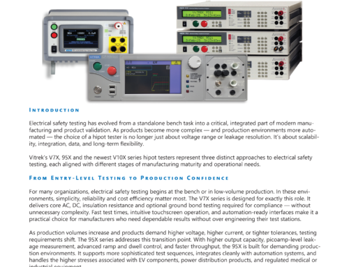
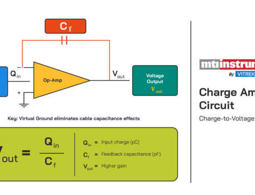
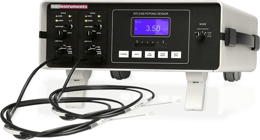
A 4-channel MTI Digital Accumeasure Amplifier converts the roller gap into a precise digital gap reding with optional analog outputs if desired. <1um accuracy can be obtained.

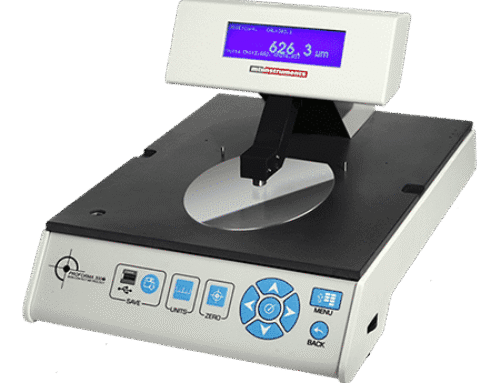
Figure 5. MTI Instruments Accumeasure D400 amplifier with four independent measurement channels.
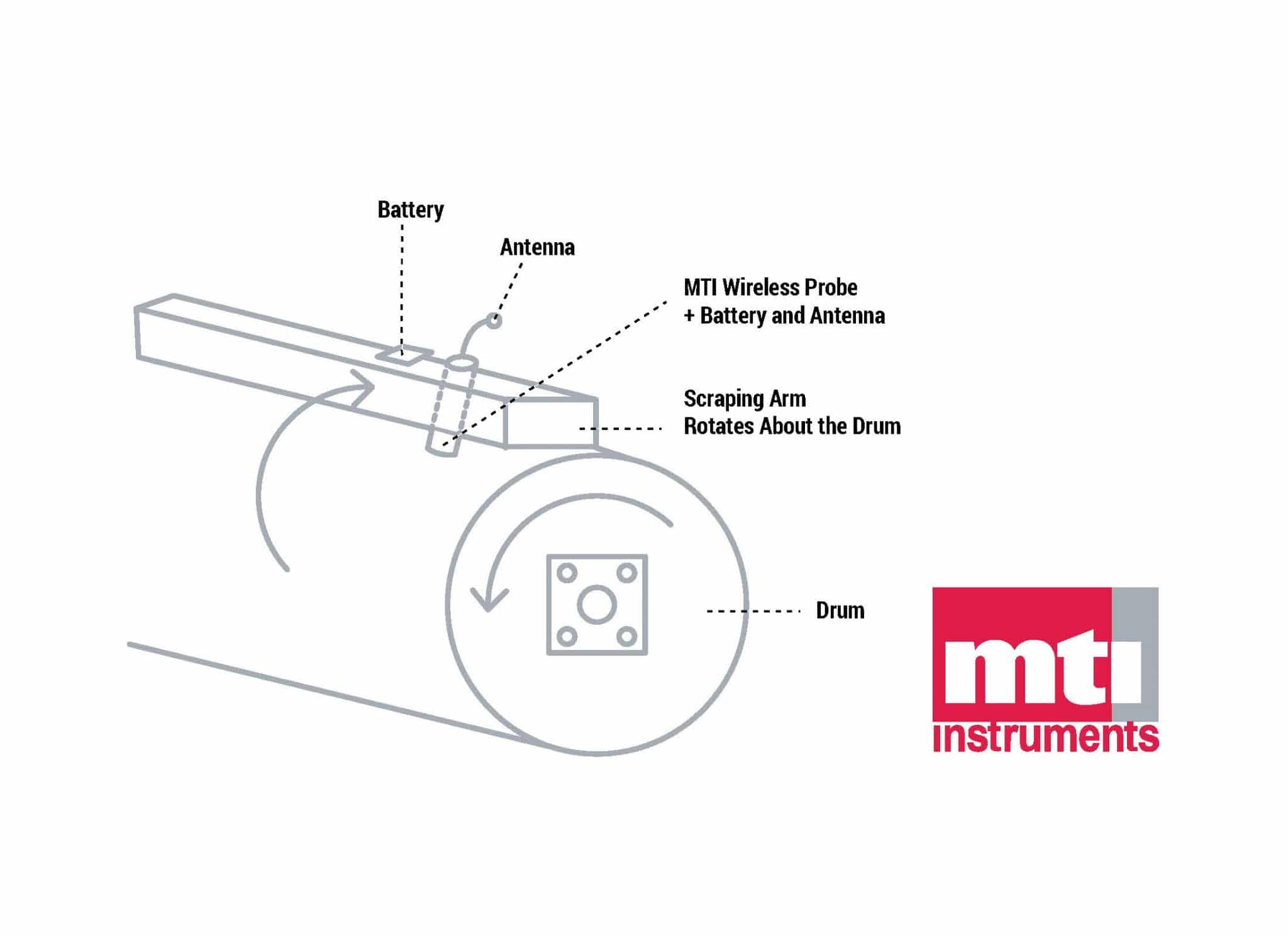
Depending on how well the rollers can be machined with a 1 mm x 25 mm relief cut its likely there will also be some run out of the relief cut relative to the roller surface. Installing an additional rotary encoder on the roller can allow tracking of the roller surface relative to the relief cut. The MTI Digital Accumeasure also has two quadature digital inputs that can be connected to the rotary encoder allowing synchronization of the gap reading with the encoder input.
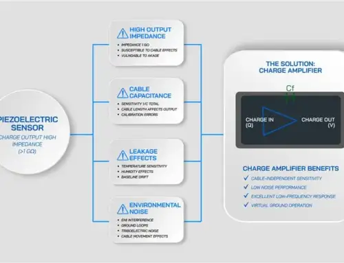
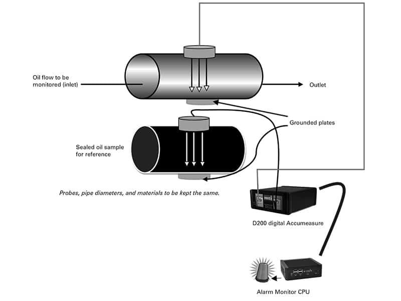
To work, the amplifier injects a current into each probe, and then measures the impedance of the respective capacitive gaps. The impedance measured is directly proportional to the probe/roller gap by the formula: Gap = (area of the probe X dielectric constant of air) / (capacitance of the gap).
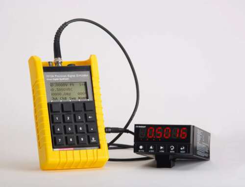
Summing the two probe/roller gaps, and adding the respective probe thicknesses, gives the gap between rollers. If roller grounding is poor or non-existent, a wand equipped with MTI’s Push-Pull probes can be used to make the measurements (Fig 6).

Figure 6. MTI’s Push-Pull probes feature two sensing elements built into one probe body eliminating the
need to electrically ground the rotor.
Benefits
• Non-contact measurement eliminates mechanical error
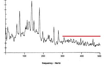
• Gap measurements can be electronically stored for future reference (Fig 7)
• The capacitance amplifier can be networked for process control and active gap control
• Real-time monitoring spots excessive bearing play

Figure 7. Plot of a changing gap as would be encountered when adjusting a roller gap.


