
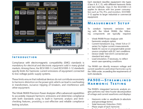
Creating a Data Link Signal Integrity Test Platform
This application note describes how a manufacturer of data links utilizes GaGe Instruments’ PC-based
high-speed data acquisition digitizers to perform production-level signal integrity testing.

Data Link Device Testing
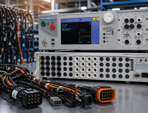
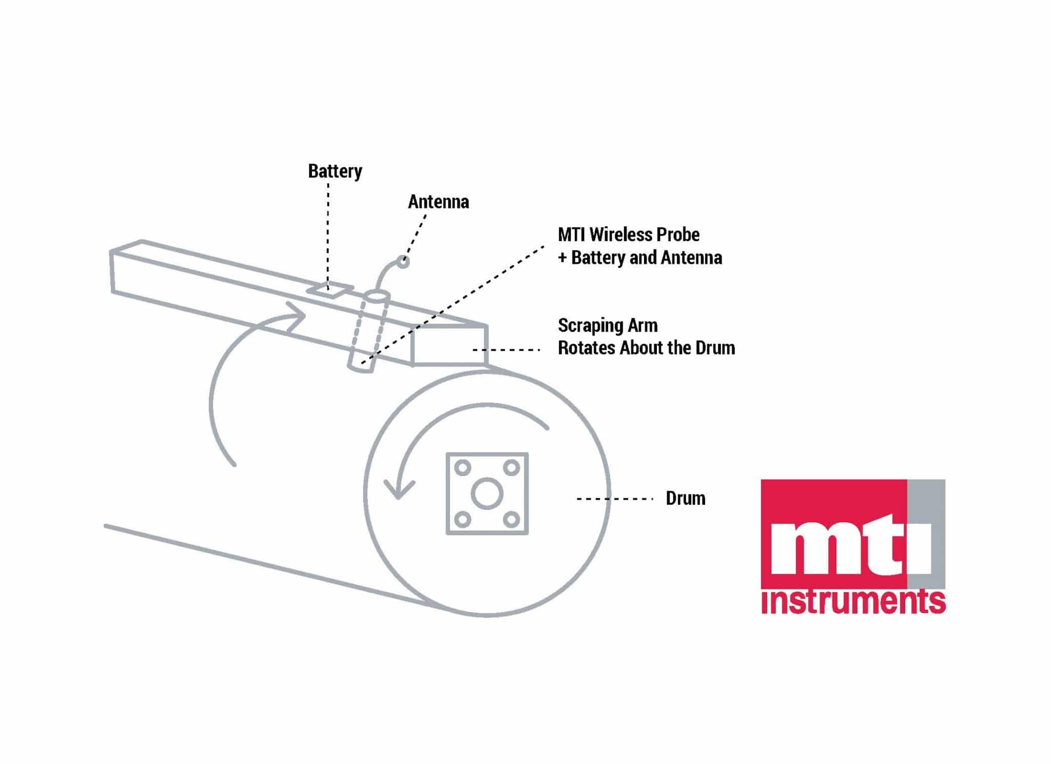
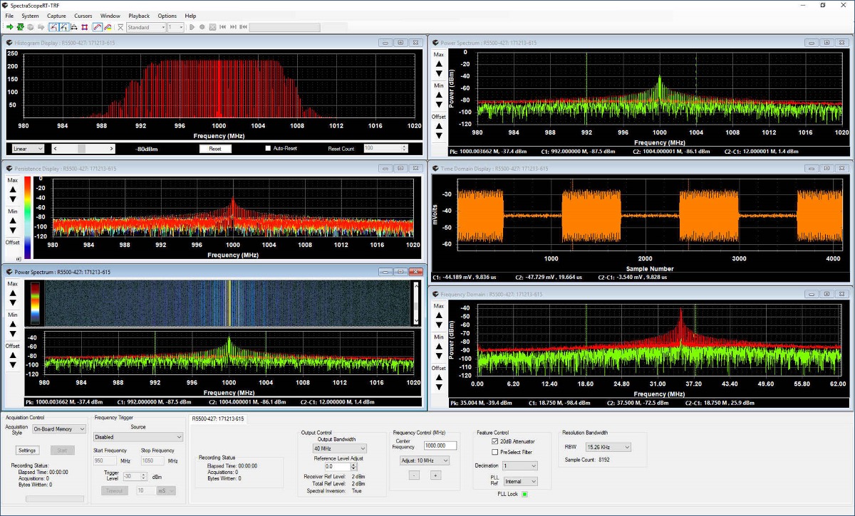
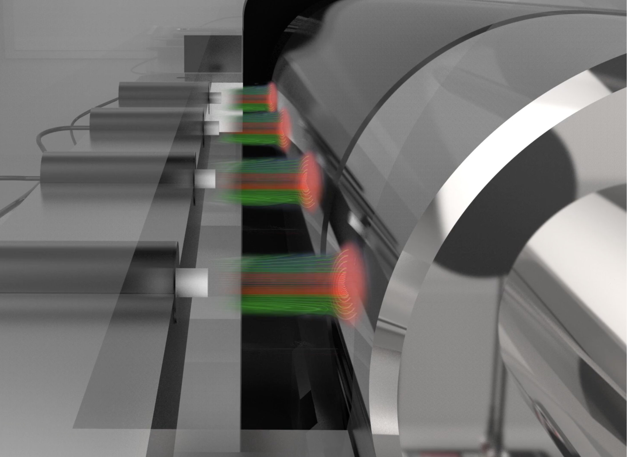
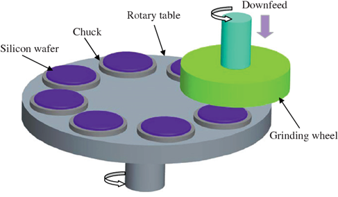
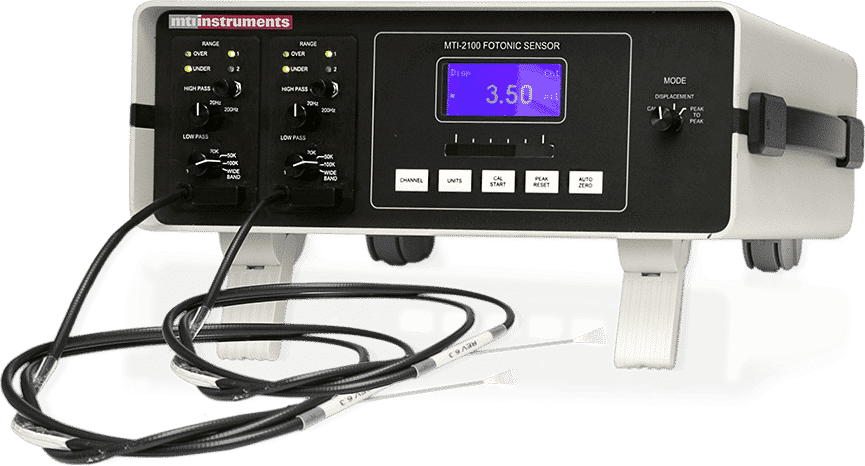
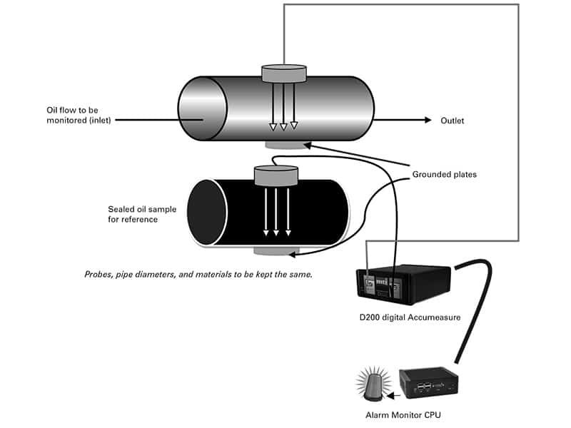
The data link device under test (Figure 1) is characterized by comparing test signals that are input to the link with signals measured at the link output. Differences between these two test signals indicate a degradation by the link during transmission.
The input and output test signals require sampling at 1 GS/s (GigaSample per second) with at least 14-bit vertical resolution. Both signals must be continuously recorded for durations ranging from a few seconds to several minutes.

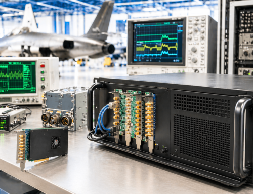
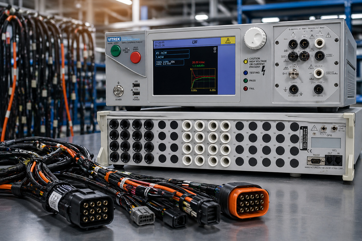
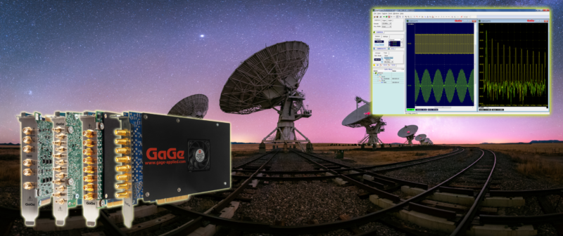
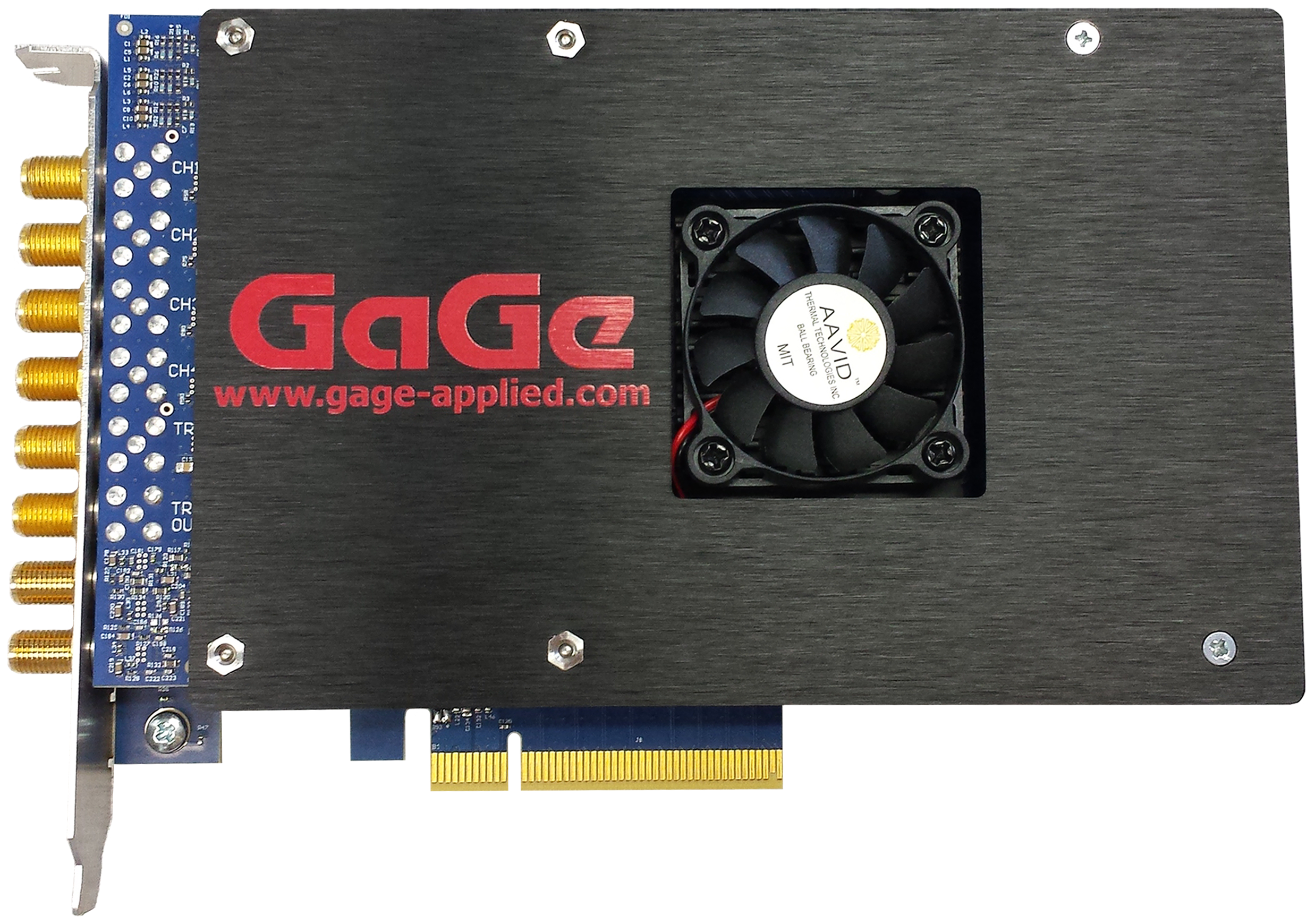
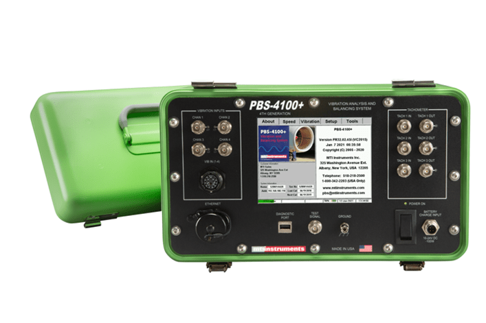
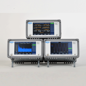
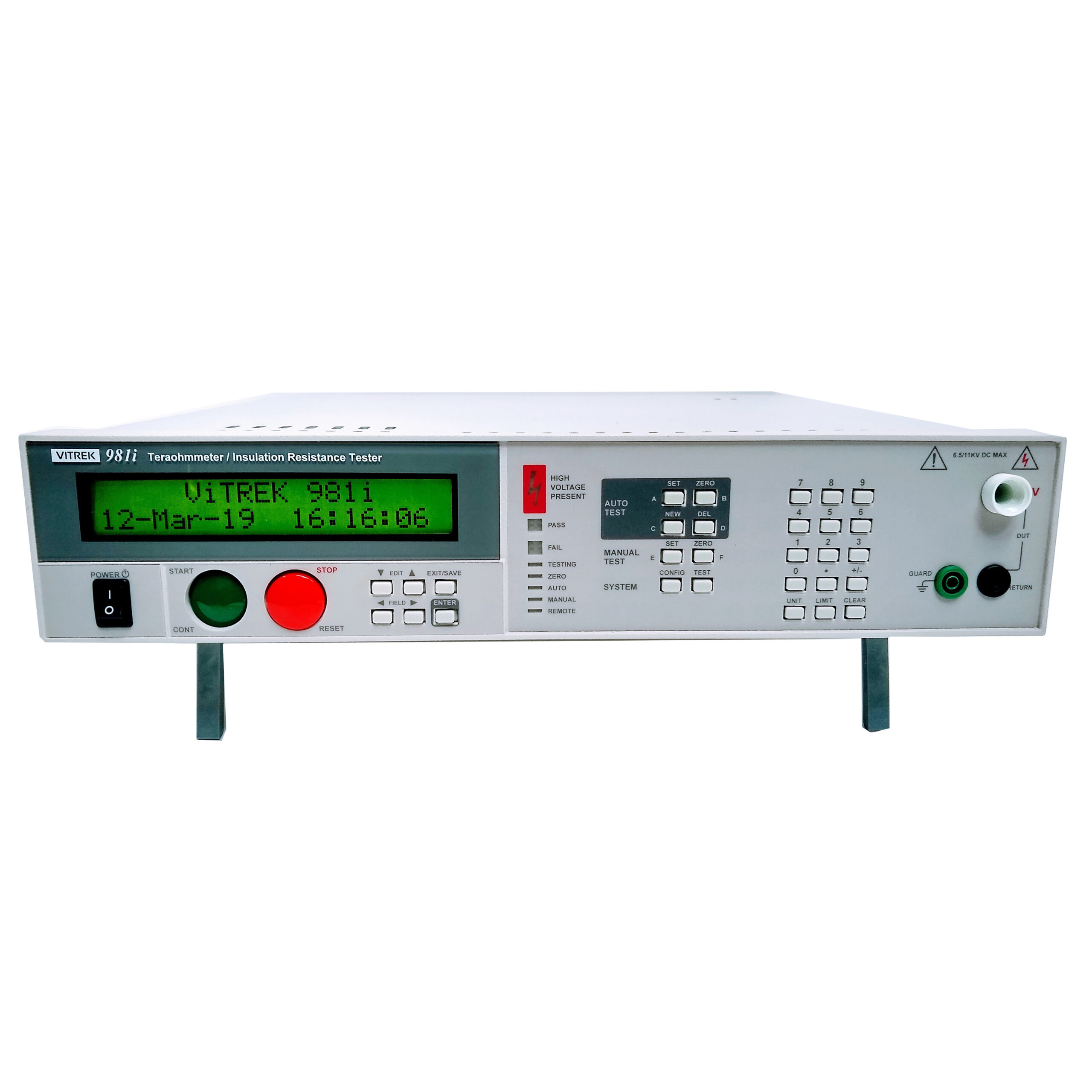
Figure 2. The GaGe RazorMax data acquisition system is offered on both PCIe and PXIe platforms.
The Test
The test setup utilizes two PC platforms for transmitting and receiving the data — each using a different protocol — PCI Express (PCIe) and PXI Express (PXIe), respectively.
To acquire the input and output link signals for their link characterization system, the company selected two GaGe 16-bit digitizers, the RazorMax PCIe CSE 161G2 and the PXIe CSX161G2 (Figure 2). The RazorMax provides the required 1 GS/s sampling rate in addition to 16-bits of vertical resolution, which exceeds the 14-bit requirement.
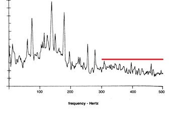
The two different RazorMax models use the same GaGe digitizer circuitry and differ only in residing on different platforms (PCIe and PXIe). Accordingly, the input and output signals (Fig 3a and 3b) utilized by the test platform software are obtained by effectively identical RazorMax instruments, which is an optimum way to reveal small signal differences due only to transmission degradation.

Figure 3. A GaGe PCIe digitizer captures the input signal (a) being sent to the data link while a GaGe PXIe digitizer captures the output signal (b). The signals are then compared using analysis software.
The RazorMax’s 700 MHz analog input bandwidth and 1 GS/s sampling rate permit characterization of data link signals at up to 500 MHz frequency. The 4 GigaSample onboard RazorMax memory allows continuous signal acquisition for up to four seconds. For much larger durations, the user can stream RazorMax through the PCIe or PXIe bus directly into PC RAM and then on to a fast storage drive system.
The Results
The manufacturer initially demonstrated a prototype system using GaGe’s powerful turnkey software. A final C-based software application applies company proprietary analysis to acquired signals and produces final link characterization measurements.
By employing GaGe’s high-performance digitizer hardware with its ultra-fast data transfer capability and powerful software library, the customer was able to quickly construct a complete high-performance link characterization system.


