Introduction
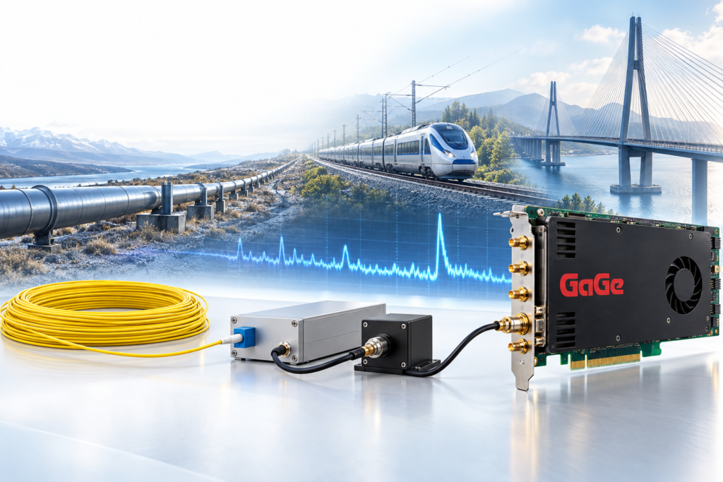
An exciting new technology called Distributed Fiber Optic Sensing (DFOS) transforms ordinary communications fiber into a continuous sensing array that extends over kilometers. Communications fiber is designed to minimize optical attenuation and maximize the transmitted optical signal. Nonetheless, a small amount of light is backscattered towards the light source. This backscatter is routinely acquired by Optical Time-Domain Reflectometers (OTDRs) to characterize fiber. Modern communications fiber typically has a very low attenuation of about 0.2 dB/km. DFOS instruments similar to OTDRs are generally called interrogators.
Backscatter is divided into two types. Elastic backscatter occurs at the same energy (or, equivalently, frequency or color) as the incident light. Inelastic backscatter occurs at a different energy (or frequency or color) as compared with the incident light. This energy difference is given to or taken from the light by the fiber itself.
Elastic backscatter is generally of higher amplitude than inelastic backscatter. Accordingly, conventional OTDRs measure elastic backscatter, which is a primary cause of communications signal attenuation. DFOS interrogators designed to measure inelastic backscatter must filter out stronger elastic backscatter signals.
A DFOS method called Distributed Acoustic Sensing (DAS), detects light that is backscattered elastically by the fiber. Distributed Temperature Sensing (DTS) measures Raman backscatter, in which photons exchange energy with molecular vibrational modes in the fiber. Distributed Strain Sensing (DSS) measures Brillouin backscatter, in which photons interact with acoustic waves propagating through the fiber.
In the majority of DFOS applications, a sub-microsecond laser pulse is initially launched down the fiber sensor, and a small backscatter signal is detected. As in radar and ultrasonics, the arrival time of the backscattered DFOS signal from position x within the fiber is equal to the round-trip travel time Δ t of the light for that position. If a laser pulse is emitted at time t= 0 from position x=0, then the familiar governing reflectometry equation is:

where v is the propagation speed. For communications fiber, the light propagation speed is about two-thirds of the speed of light in vacuum or 20 cm/nanosecond, which is coincidentally very close to the speed of electrical signals within co-axial cable.
A change in temperature, strain, vibration, or another DFOS event occurring at position x may produce a corresponding change in the detected backscatter signal at time Δt after pulse emission, as determined by the above equation. If this response signal is transformed into a sensor measurement, then the complete time-domain DFOS signal yields a continuous distributed measurement along the fiber.
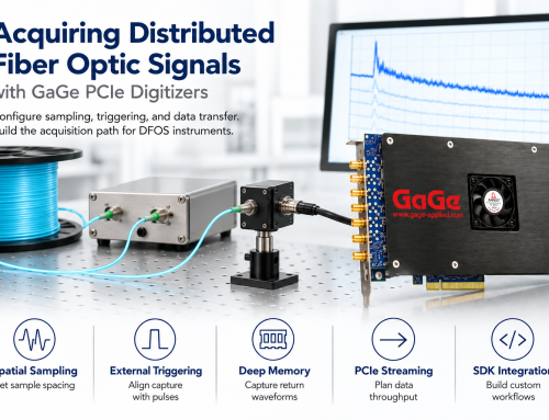
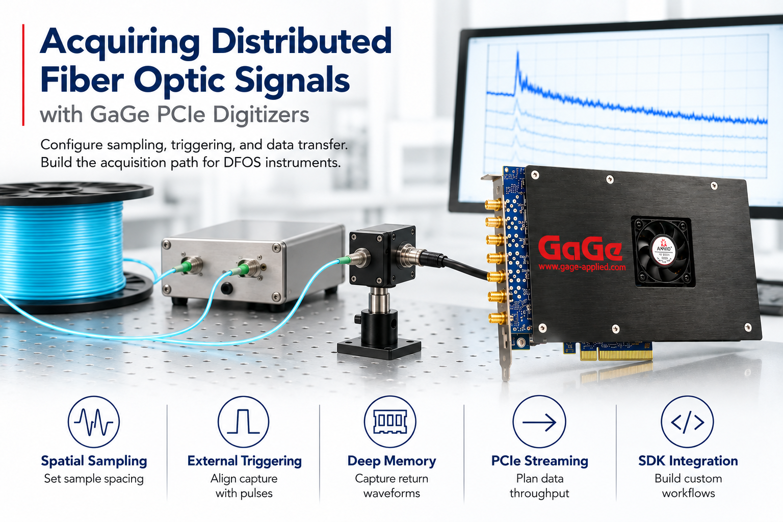
DFOS backscatter signals are detected by a photodiode whose output is acquired by a high-speed waveform digitizer, whose performance is critical to the quality of the DFOS measurement. The digitizer is externally triggered by emission of the laser pulse so that the digitizer measures travel times Δt directly. The total waveform duration is equal to the time required for backscatter to return from the end of the fiber.
In principle, a continuous time-domain DFOS signal provides measurements from a continuous array of distributed sensors. In practice, however, DFOS signals are sampled discretely by the digitizer at a constant sampling rate. The corresponding sampling interval determines the Channel Spacing—the distance between successive spatial samples of the distributed measurement. If we use the reflectometry equation above and the value for v, we obtain:
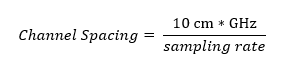
For example, a Channel Spacing of 10 cm requires a sampling rate of 1 GHz or 1 GS/s. DFOS systems may use even higher sampling rates to improve precision. However, 1 GS/s is the minimum sampling rate for a 10 cm Channel Spacing.
Multiplying a 100-nanosecond laser pulse width by the 20 cm/ns propagation speed, for example, gives a physical pulse length within the fiber of 20 meters. Accordingly, backscatter signals are effectively averaged over this distance. Narrower laser pulses improve the ability to resolve fine spatial variations in measured quantities, but the total pulse energy is proportionally reduced. Conversely, wider and more energetic pulses generate stronger backscatter signals from longer fibers but at the expense of sensitivity to finer profile features.
The number of samples that the digitizer must acquire after each pulse trigger is equal to the fiber length divided by the Channel Spacing. For our example Channel Spacing of 10 cm, a 1 km fiber length requires 10 kiloSamples to be acquired after each laser pulse trigger.
At 1 GS/s, 10 kiloSample waveforms are acquired in 10 microseconds, after which another laser pulse may be generated to acquire a new DFOS waveform. Accordingly, a 100 kHz DFOS trigger rate (also known in radar as a Pulse Repetition Frequency (PRF)) is achievable.
This 100 kHz rate becomes a second sampling rate that determines the speed at which time-dependent phenomena may be studied. By the Nyquist sampling theorem, this corresponds to a maximum measurable frequency of 50 kHz, which allows DFOS to monitor phenomena with frequencies extending into the audio range.
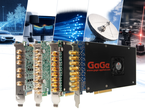
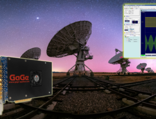
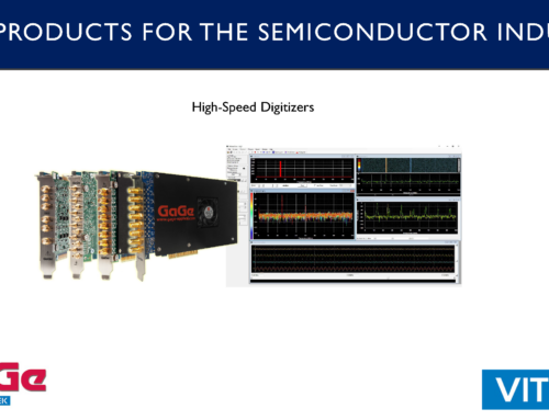
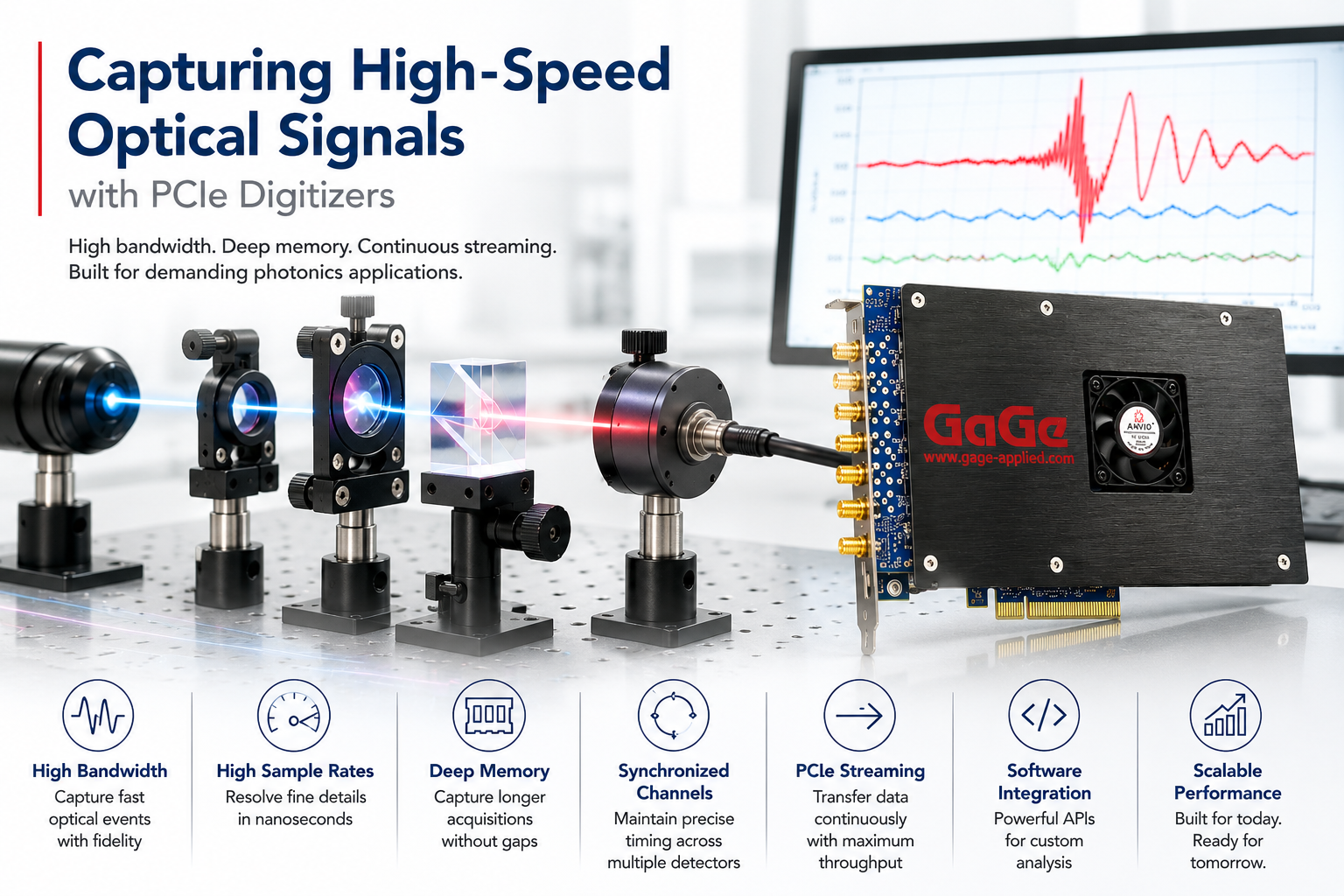
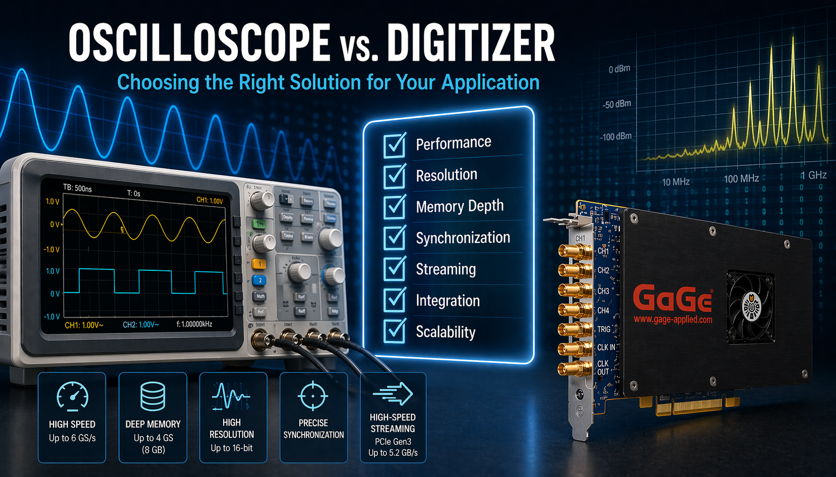
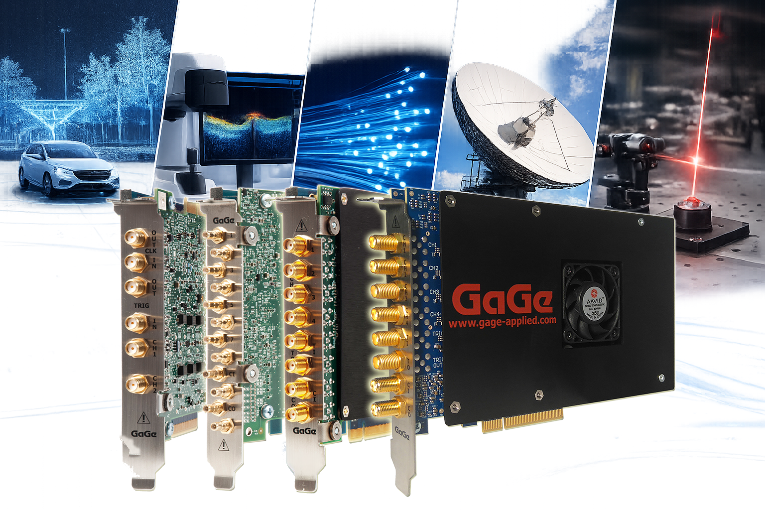
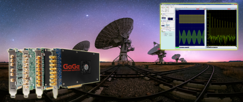
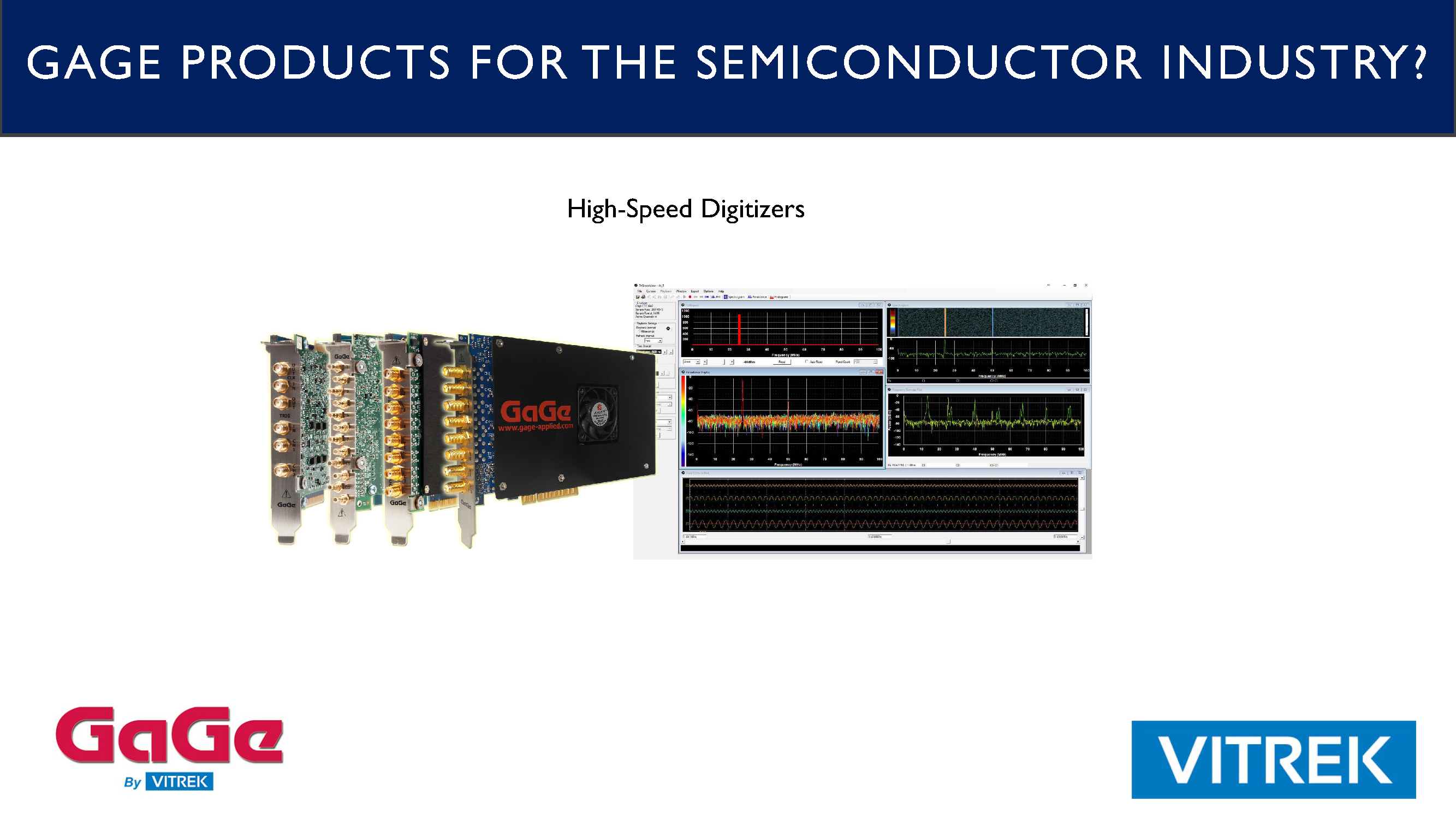
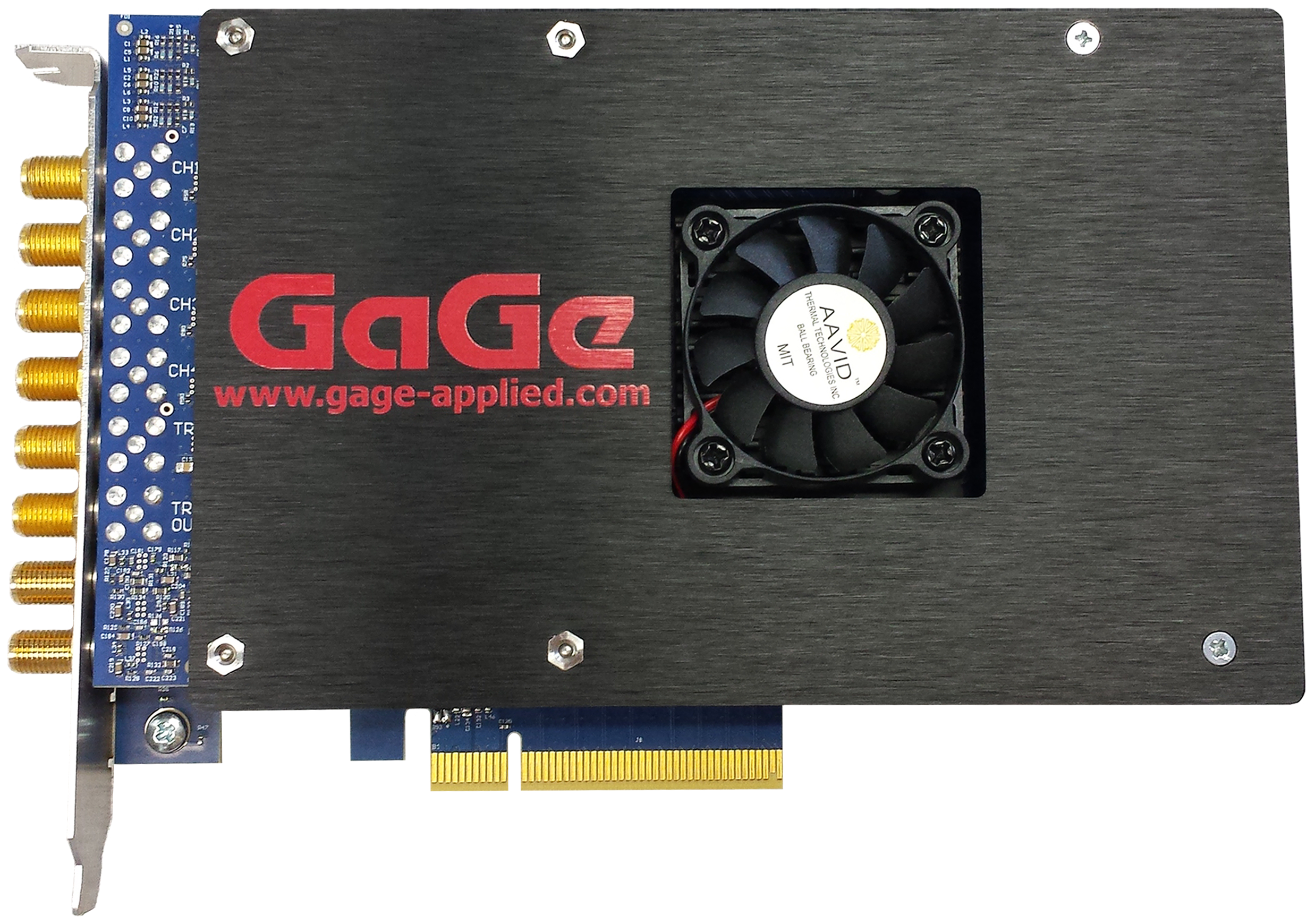
Gage digitizers are an exceptionally powerful platform for DFOS applications, combining high sampling rates, multiple simultaneous channels, large onboard memory, high vertical resolution, flexible triggering, and extremely rapid waveform acquisition. Multiple simultaneous input channels are important in some DFOS applications, such as DTS. With sampling rates up to 6 GS/s, Gage digitizers can provide Channel Spacings below 1 cm—far finer than the requirements of most DFOS systems. Up to 8 GB of onboard acquisition memory allows long DFOS waveforms to be captured at full sampling rate without requiring continuous transfer to the host PC.
DFOS backscatter signals generally decrease approximately exponentially with distance and so have high dynamic range, which means that they contain both high amplitude and low amplitude sections.
High dynamic range signals are best acquired by a digitizer with high vertical resolution. This makes high vertical resolution particularly important in DFOS, where the digitizer may need to resolve weak backscatter signals after acquiring much stronger signals from other portions of the fiber. Most of Gage’s digitizer models have a high 16-bit vertical resolution, which provides a raw dynamic range of almost 100 dB.
Gage Digitizers allow usage of a Trigger Delay, which drops a specific number of samples after the trigger. This allows users to completely ignore any uninteresting lengths of fiber by not acquiring samples within them. Instead of repeatedly acquiring and processing kilometers of irrelevant fiber, the user can configure the digitizer to acquire only the section of interest.
Gage digitizers can stream waveform data to the host PC as new waveforms are being acquired. Further, they can re-arm themselves within a microsecond after completion of a waveform acquisition.
Finally, Gage digitizers fit into conventional PCs and can be readily integrated into a complete DFOS instrument using Gage’s software development kits. This gives system developers an unusual combination of high-performance data acquisition and the flexibility of a PC-based architecture. The result is a remarkably flexible DFOS acquisition platform: high-speed digitization, high vertical resolution, large onboard memory, flexible triggering, rapid re-arming, streaming, and multiple simultaneous inputs—all in a conventional PC-based system that can be integrated directly into the customer’s DFOS software.
Request a Free Demo
See how GaGe digitizers can deliver the speed, signal fidelity, and acquisition flexibility your most demanding measurement applications require. A Vitrek application engineer will follow up within one business day.