When a production line fails a compliance audit, the problem is often not the hipot or ground bond test itself. It is the gap between the instrument, the operator, the product variant, and the record that proves the test was run correctly. A well-designed electrical safety test automation workflow closes that gap by making test execution, decision logic, and data capture consistent from unit to unit.
For manufacturers in medical devices, EV subsystems, appliances, industrial controls, and defense electronics, that consistency matters for more than throughput. Electrical safety testing sits at the intersection of operator safety, product certification, and traceable quality records. If the workflow is loosely defined, even a capable instrument can become part of a brittle process. If the workflow is engineered correctly, automation can reduce retest rates, tighten compliance, and make failures easier to diagnose.
What an electrical safety test automation workflow really includes
In practice, the workflow is more than a script that triggers a hipot sequence. It includes test selection, product identification, fixture interlocks, parameter control, operator prompts, pass-fail logic, results storage, and exception handling. In regulated environments, it also includes calibration status, user access control, and the ability to show that the right limits were applied to the right product revision.
That broader definition matters because many automation efforts stall when teams focus only on instrument command sets. Sending remote commands over LAN, USB, or GPIB is the easy part. The harder part is building a repeatable process around product variation, operator behavior, and documentation requirements.
A practical workflow usually starts before voltage is applied. The system needs to know what is being tested, what standard or internal specification applies, what fixture is connected, and whether all safety conditions are met. Only then should the sequence proceed to dielectric withstand, insulation resistance, ground continuity, leakage current, or other required tests.
Why manual electrical safety testing breaks down at scale
Manual methods can be acceptable in low-volume engineering validation, especially when experienced technicians are working through early design iterations. In production, the same approach creates avoidable risk. Operators may select the wrong program, skip a prompt, misread a fixture status, or record results in a disconnected database hours later.
The cost of those mistakes is not limited to scrap. A false fail reduces throughput and drives unnecessary troubleshooting. A false pass is more serious because it can affect certification status, field reliability, and user safety. Even when the measured values are correct, poor data handling can leave the organization unable to demonstrate compliance during an audit or customer review.
Automation addresses these issues, but only if the process accounts for edge cases. A workflow that speeds up normal operation while ignoring rework handling, barcode errors, or fixture wear will simply move the bottleneck.
Building the workflow around the product and the standard
The best starting point is the test requirement, not the software interface. Engineers should map each product family to its applicable safety standards, internal limits, and manufacturing constraints. That means defining the exact test types, voltage levels, ramp times, dwell times, current limits, and pass-fail thresholds, along with any sequencing rules.
This is also where trade-offs appear. A single universal test sequence may simplify administration, but it can be inefficient for mixed-product lines. Product-specific sequences improve cycle time and control, but they add configuration management overhead. The right choice depends on volume, revision frequency, and how often test limits change.
Once requirements are stable, the workflow can be organized into a controlled sequence. Product identification should call up the correct test recipe automatically. Fixture verification should confirm that the intended DUT connection is present. Interlocks should prevent unsafe initiation. The instrument should execute the sequence with locked parameters rather than relying on operator entry. Results should be written directly to a traceable record with timestamps, serial numbers, operator IDs, and equipment IDs.
Key elements of an effective electrical safety test automation workflow
Instrument control and parameter integrity
The workflow should treat test parameters as controlled data. If operators can modify limits on the fly, repeatability suffers and audit exposure increases. A better approach is role-based access with approved recipes maintained under revision control.
Instrument integration should also support positive confirmation that the loaded program matches the intended product. In higher-risk applications, teams often add checksum validation or recipe approval logic in the supervisory software to reduce the chance of running an outdated configuration.
Safety interlocks and fixture awareness
Electrical safety automation must protect the operator first. That means door switches, dual-action start controls where appropriate, emergency stops, discharge verification, and fixture presence checks. For high-voltage testing, the workflow should explicitly handle charge dissipation before allowing part removal.
Fixtures deserve more attention than they usually get. A worn probe, contaminated contact surface, or intermittent ground path can create unstable results that look like product defects. Many false failures originate in fixturing, not the DUT. Building fixture validation into the workflow can save significant debugging time.
Data capture and traceability
A pass indicator alone is not enough. The workflow should capture the measured values, the limits applied, the instrument used, calibration status, the software revision, and the product identifier. In some environments, waveform or event-level detail is also useful, especially when troubleshooting intermittent breakdowns or leakage behavior.
This record structure becomes more valuable over time. It supports root-cause analysis, process capability studies, customer documentation, and audit response. It also helps test managers distinguish between a real product shift and a measurement-system problem.
Exception handling
Most systems are designed for the ideal path. Strong workflows are designed for the non-ideal one. What happens when a barcode does not scan, a test aborts mid-cycle, network storage is unavailable, or the DUT fails the first step? The workflow should define what gets blocked, what gets logged, and what actions require supervisor approval.
Without that logic, operators invent local workarounds. Those workarounds may restore output in the short term, but they weaken control of the process.
Integration choices depend on production reality
Some operations need a fully integrated station tied to MES, ERP, and plant historians. Others need a self-contained cell that exports validated records at the end of a shift. There is no single correct architecture.
For high-volume manufacturing, direct integration with factory systems can reduce transcription errors and support real-time containment when failures trend upward. For lower-volume or high-mix environments, a more modular setup may be easier to validate and maintain. The trade-off is usually between central visibility and local flexibility.
The same applies to software strategy. Off-the-shelf test executive platforms can speed deployment, especially when teams need standard UI elements, reporting, and instrument drivers. Custom software may be justified when product logic, fixture control, or cybersecurity requirements are unusually specific. In either case, the design should prioritize deterministic behavior, maintainability, and validation discipline over feature count.
Common implementation mistakes
One common mistake is automating an unstable manual process. If the original test method has unclear fixturing, inconsistent contact quality, or loosely defined limits, software will not fix it. It will only make the inconsistency happen faster.
Another is ignoring measurement uncertainty and instrument capability. A workflow can be technically automated and still be poorly matched to the test requirement. Voltage accuracy, current resolution, discharge behavior, switching characteristics, and timing control all affect whether the data is trustworthy.
A third mistake is treating reporting as an afterthought. If result records are not structured correctly from the start, teams often end up with data they cannot search, compare, or defend during an audit. That is particularly costly in regulated industries where proof of process control matters as much as the individual pass-fail result.
What improvement should look like
A successful automation project should reduce operator dependence without reducing engineering visibility. Throughput should improve, but not at the expense of test rigor. Failure analysis should get easier because the system captures more context, not less.
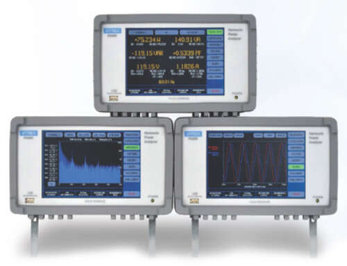
In many cases, the first measurable gains are fewer setup errors, more consistent cycle times, and better traceability. Larger gains often come later, after teams use the accumulated data to refine limits, detect fixture degradation, and identify product design issues earlier in the process. That is where an engineering-grade platform, such as those developed by Vitrek for electrical safety and high-voltage test environments, can make the workflow more dependable over the long term.
The strongest electrical safety test automation workflow is not the one with the most screens or the most integration points. It is the one that applies the right test, in the right order, under controlled conditions, and leaves behind a record that can stand up to engineering review and compliance scrutiny. If you build the workflow around that standard, automation becomes a quality control tool rather than just a faster button press.


