![]()
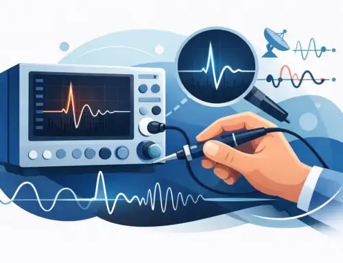
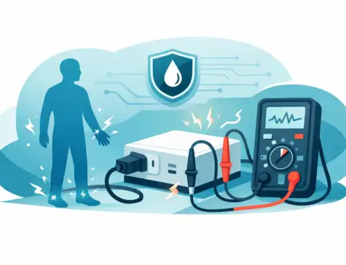
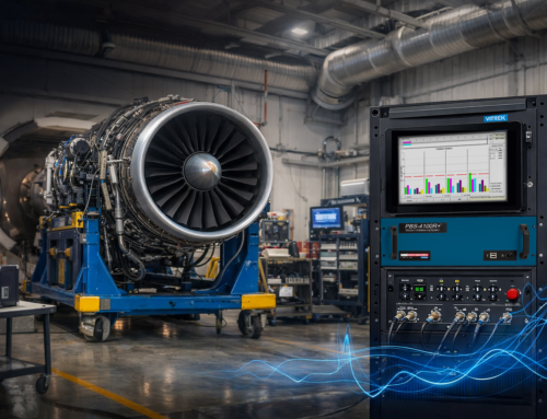
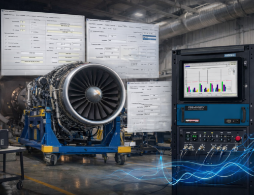
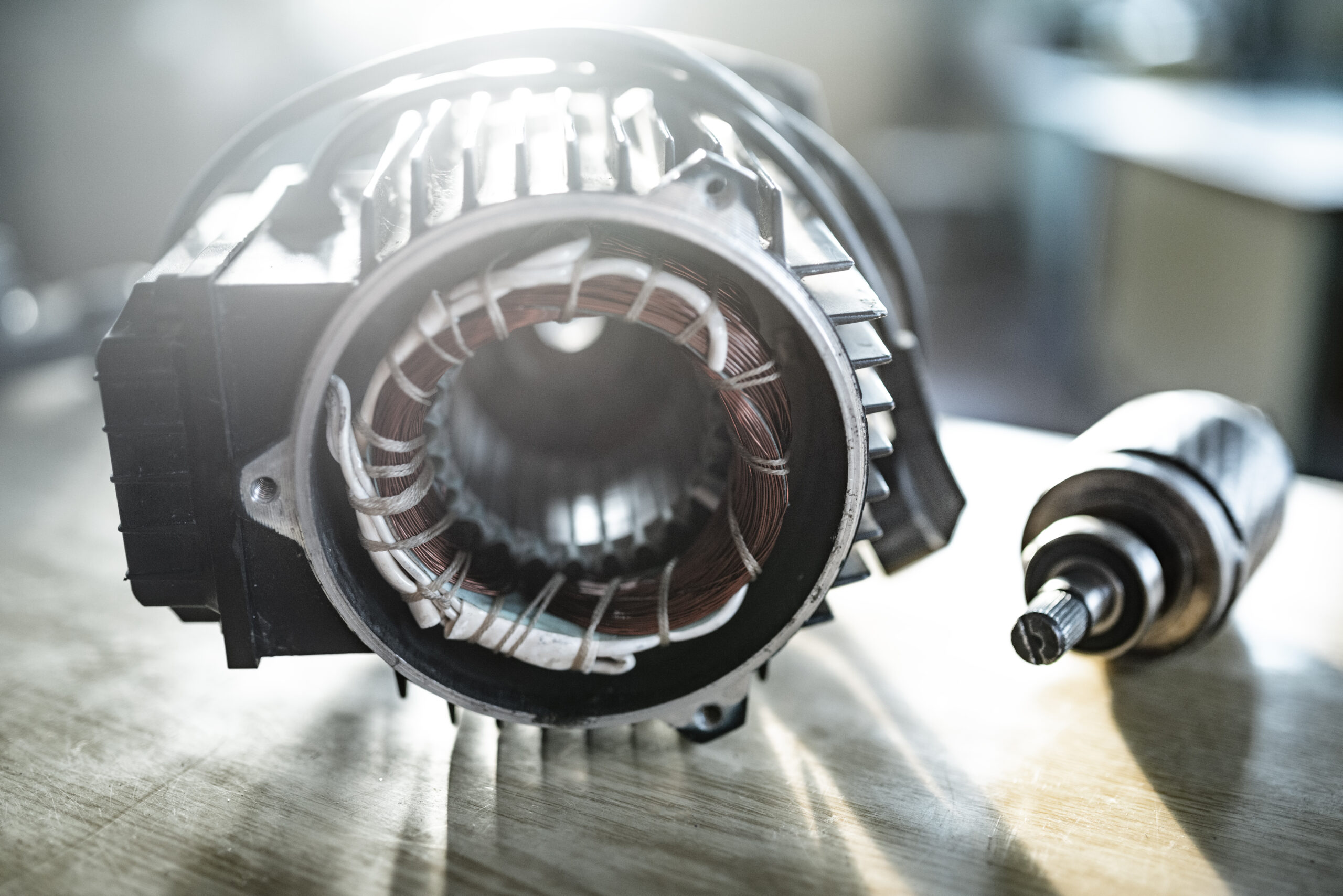
Accelerometers play a crucial role in measuring vibration for aircraft engines, industrial machinery, and structural health monitoring. But like any precision instrument, their readings can drift over time, affecting data accuracy. That’s where accelerometer calibration becomes essential.
Whether you’re verifying sensors in a lab or testing data acquisition systems in the field, following a structured calibration approach ensures your vibration measurements remain accurate, traceable, and compliant with industry standards.
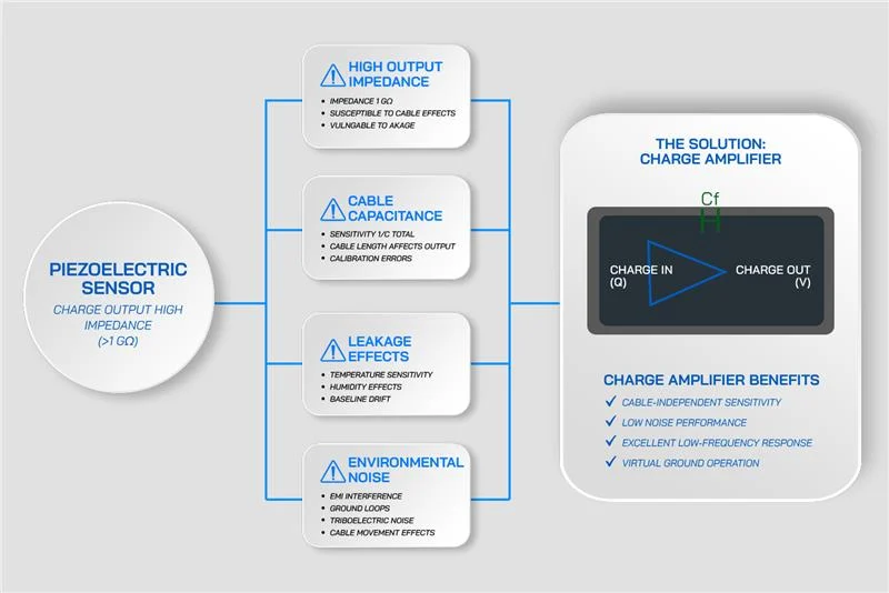
What Is Accelerometer Calibration?
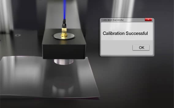
Accelerometer calibration is the process of comparing the sensor’s output against a known reference standard to determine if it’s producing accurate results. If there’s a deviation, adjustments or compensations are applied.
Calibration ensures an accelerometer’s:
-
- Sensitivity (e.g., mV/g or pC/g)
- Frequency response
- Phase behavior
All remain consistent with manufacturer specifications and testing requirements.
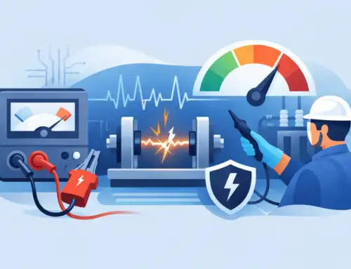
Why Is Accelerometer Calibration Necessary?
Without proper calibration:
- Critical systems may misinterpret vibration levels
- Predictive maintenance triggers may become unreliable
- Undetected faults may escalate into equipment failures
- Compliance with ISO 17025 or audit requirements may be at risk
Calibration protects your data integrity and ensures your measurements lead to the right actions.
Understanding Accelerometer Calibration Environments: Lab vs. Field
Lab Calibration
- Offers environmental control (temperature, vibration isolation)
- Uses high-end shakers or interferometers to physically excite the sensor
- Ideal for traceable, accredited calibrations (e.g., ISO 17025)
Field Calibration
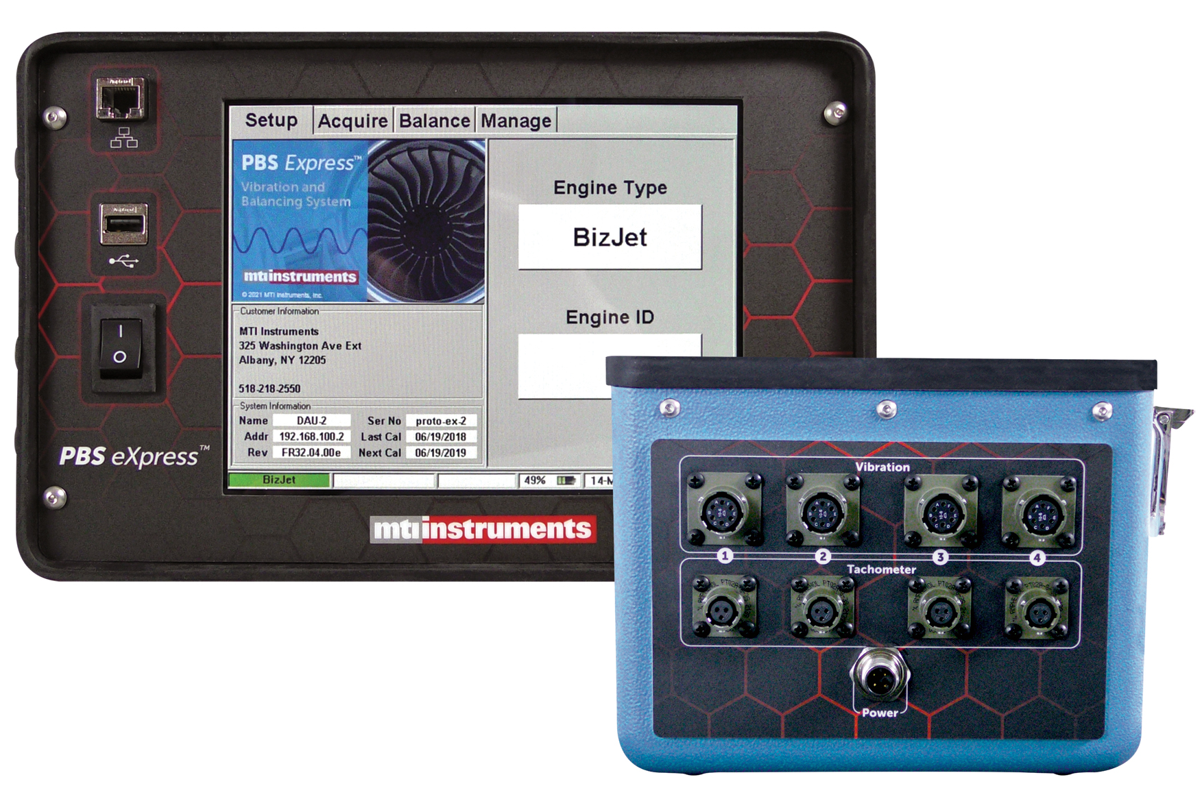
- Used for verifying system behavior or signal paths in situ
- Portable tools simulate sensor output to test data acquisition systems
- Helps identify cabling issues, signal conditioning problems, or display errors
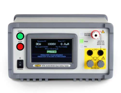
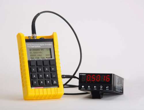
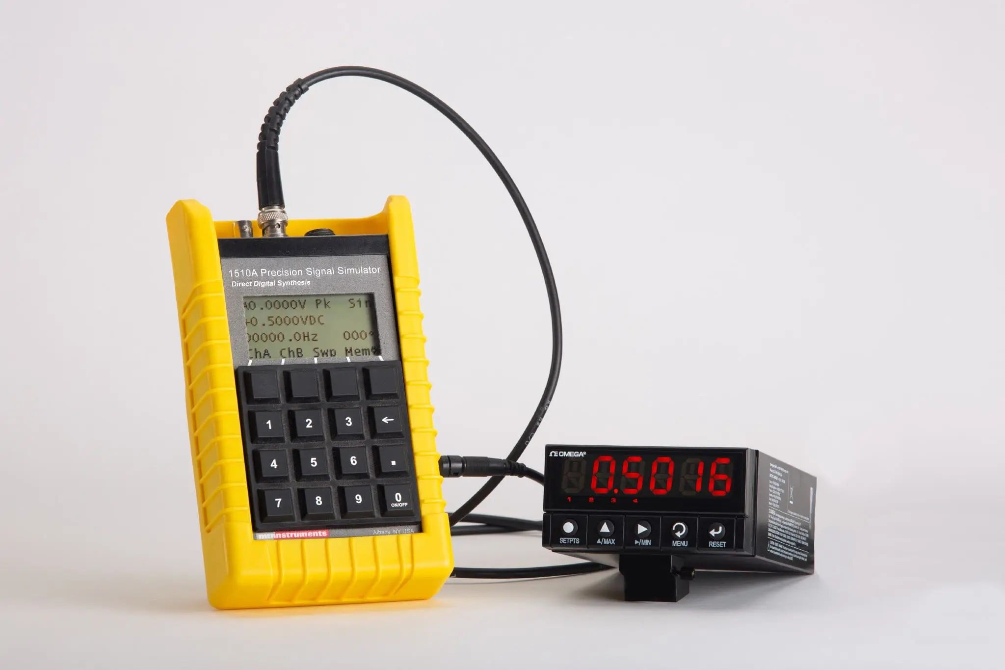
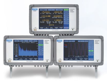
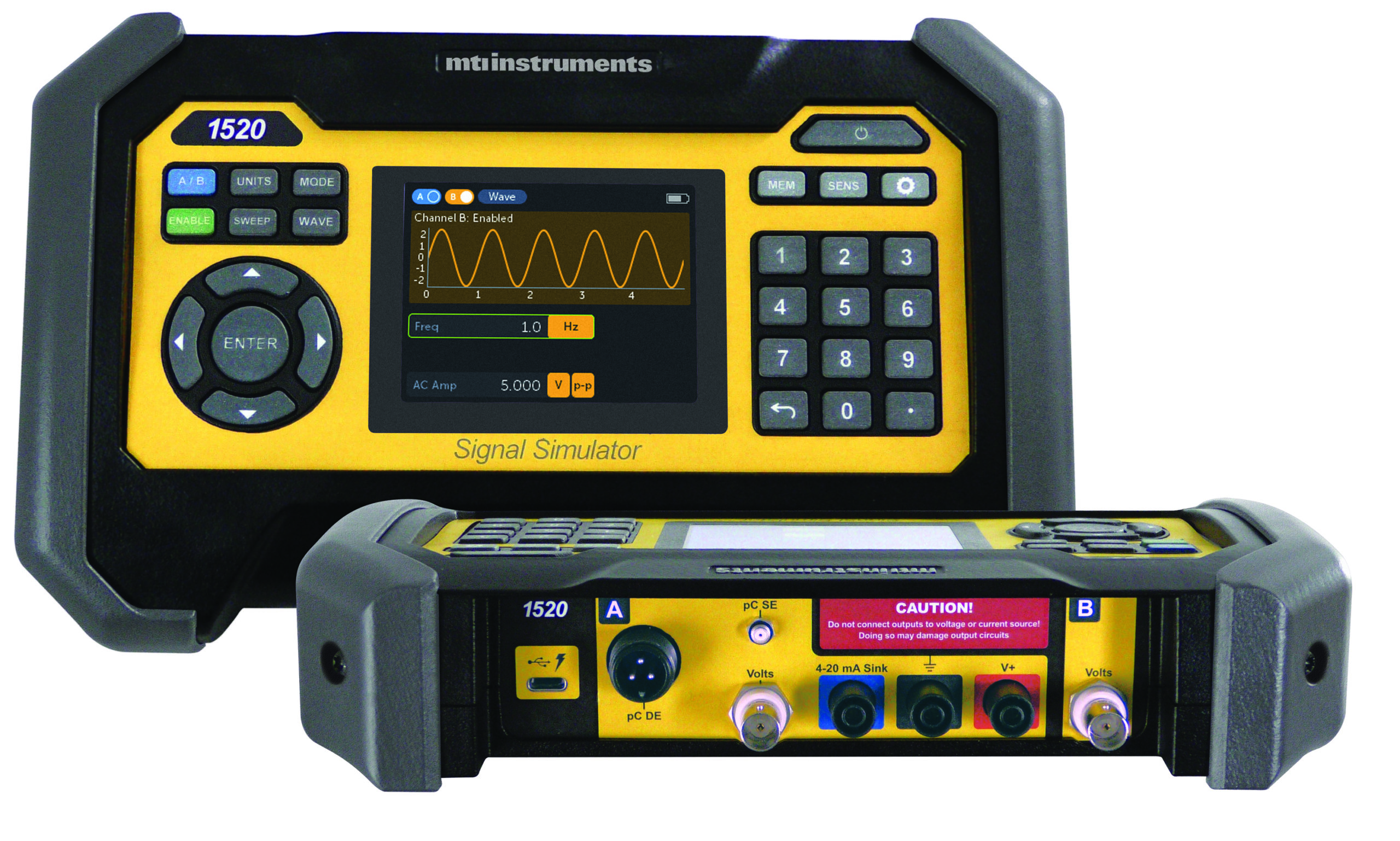
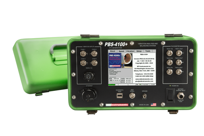
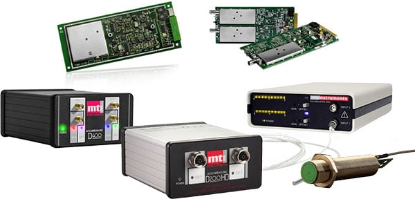
Note: Portable signal simulators like the MTI Instruments 1510A or 1520 do not perform true accelerometer calibration (i.e., they do not shake the sensor). Instead, they simulate accelerometer signals to test or calibrate downstream electronics.
Key Accelerometer Calibration Methods
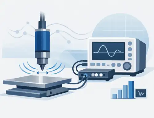
1. Back-to-Back Comparison
- Mount the test sensor atop a reference sensor on a shaker
- Compare output at known amplitudes and frequencies
2. Laser Interferometry
- Measures displacement directly to determine acceleration
- Highly precise, used in accredited calibration labs
3. Electronic Signal Simulation (Portable Signal Simulators)
- Simulates an accelerometer’s output signal (voltage or charge)
- Used to test and calibrate signal conditioning equipment, not the sensor itself
- Example: MTI 1510A simulates charge/voltage signals to validate DAQs, amplifiers, and HMIs
Calibration Parameters to Control
| Parameter | Description |
| Sensitivity | Accuracy of mV/g or pC/g output |
| Frequency Response | Sensor behavior across bandwidth |
| Amplitude Linearity | Ensures consistent output at all levels |
| Phase Response | Important for modal analysis and multi-axis systems |
Tip: Always verify calibration across the full frequency and amplitude range, not just a single point.
Importance of Traceability and Compliance
ISO 17025
- Calibration labs accredited to ISO 17025 follow strict procedures and maintain traceable records.
- Ideal for annual certification and audit readiness.
NIST Traceability
- Your calibration equipment should be traceable to national standards (e.g., NIST).
- Important for regulatory compliance and confidence in test results.
Recommendation: Use an ISO 17025-accredited lab for periodic sensor calibration. Use portable signal simulators in between to validate system functionality.
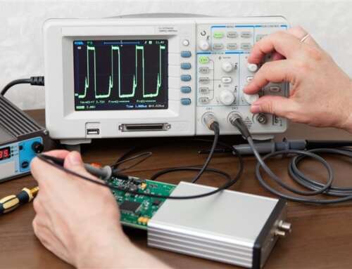
Using Portable Signal Calibrators in the Field
Portable signal simulators like the MTI Instruments 1520 or 1510A are designed for rugged environments where quick system validation is essential. While they don’t physically calibrate accelerometers, they offer powerful capabilities for verifying signal paths, DAQs, displays, and more.
Key capabilities include:
- Simulate charge and voltage signals across a wide frequency range
- Output sine, square, triangle, and custom waveforms
- Dual-channel output for phase testing
- Remote control via WiFi or Bluetooth
- Rugged, battery-powered design for field use
These tools allow a technician to quickly identify issues without needing physical vibration sources saving time, reducing downtime, and enhancing test coverage.
Best Practices for Accurate Accelerometer Calibration
- Warm up the equipment before testing for thermal stability
- Use secure sensor mounting to prevent signal errors (when using physical shakers)
- Inspect cables and connectors for integrity
- Log environmental conditions like temperature and humidity
- Document test results for traceability and audit readiness
Key Takeaways
Accurate vibration measurements depend on proper calibration and system validation. While mechanical calibration of accelerometers is critical for maintaining sensor integrity, signal simulation plays a complementary role in testing data acquisition chains, signal conditioning hardware, and system behavior.
By understanding your tools and using them appropriately, you’ll get more accurate results, faster diagnostics, and greater confidence in your vibration monitoring system.
Lab-Grade Simulation Tools, Field-Ready Design
Looking to simulate accelerometer signals with precision and portability?
Explore the MTI Instruments 1510A and 1520 signal simulators engineered to support field and lab use. With broad waveform capability, dual-channel output, and remote operation, they help ensure your systems are calibrated, verified, and ready to perform.


