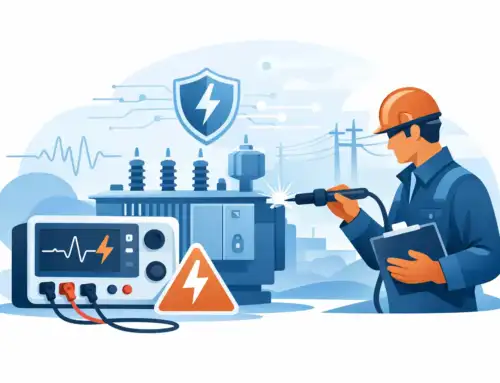
In high-voltage electrical environments, even microscopic current flows through insulation can lead to equipment damage, catastrophic failures, and life-threatening safety hazards. High potential (Hipot) testing offers defense against these risks. During testing electrical devices are subjected to controlled high-voltage stress to verify insulation integrity. However, determining what is acceptable leakage current is not easy due to multiple factors, including dielectric properties, test duration, capacitance characteristics, and regulatory requirements.
Understanding the acceptable leakage current and measuring is essential for operational reliability and regulatory compliance. Standard practice calls for the use of precsion electrical safety testers to identify potential insulation failures.
This post examines the critical aspects of Hipot testing, including acceptable current leakage limits across industries, best practices for measurement using electrical safety analyzers, and strategies to ensure your testing protocols deliver accuracy and compliance.

Overview of Leakage Current and Influencing Factors
No insulation is perfect. Although minimal leakage is inherent in all electrical devices, the critical distinction lies between acceptable operational levels and dangerous thresholds that comprise safety or regulatory compliance.
Why Leakage Current Matters
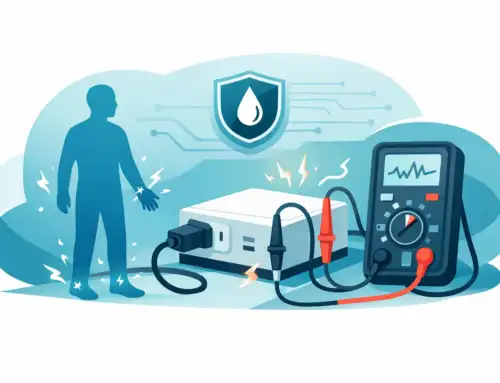
Excessive leakage current creates multiple risks that can cascade into serious problems:
- Personnel Safety Hazards: Even small currents can cause shock or electrocution
- Equipment Failures: Premature breakdown of critical components
- Regulatory Violations: Failed certifications leading to market delays or recalls
- System-Wide Shutdowns: Cascading failures in interconnected systems
- Financial Impact: Recall costs, liability claims, and damaged reputation
Key Factors Influencing Leakage Current
Several factors influence what levels are considered acceptable in different applications:
Operating Voltage: Higher operating voltages stress insulation materials more severely. A 480V industrial motor will have different limits than a 240V household appliance, reflecting the relationship between material response and voltage stress.
Product Classification and Risk Profile: Regulatory bodies establish different limits based on end-use risk profiles:
- Medical devices demand the strictest limits due to patient safety concerns
- Industrial equipment allows higher thresholds in controlled operating environments
- Consumer products balance safety requirements with practical manufacturing considerations
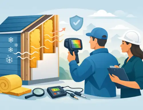
Operating Conditions: Temperature and humidity significantly affect insulation performance. High temperatures can reduce dielectric strength, while high humidity creates surface conduction paths. These factors must be considered when establishing test parameters and acceptance criteria.
Cable and Connection Configuration: Long cable runs increase capacitive coupling between conductors and ground, leading to measurable but non-hazardous leakage. Capacitive coupling will mask true resistive leakage if not properly analyzed during testing.
Insulation Properties Different materials exhibit varying leakage characteristics under voltage stress. Understanding material behaviour-from basic PVC to advanced ceramic insulators-enables engineers to set appropriate limits and choose optimal testing parameters.
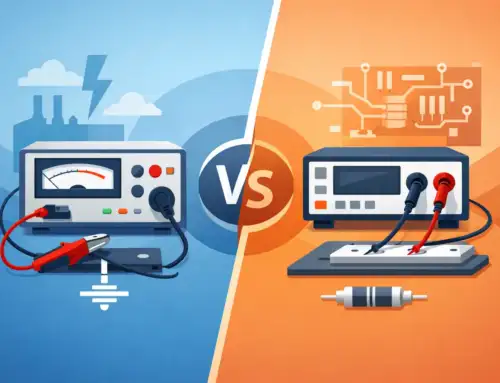
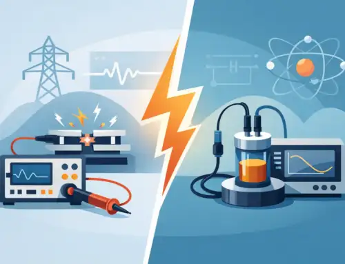
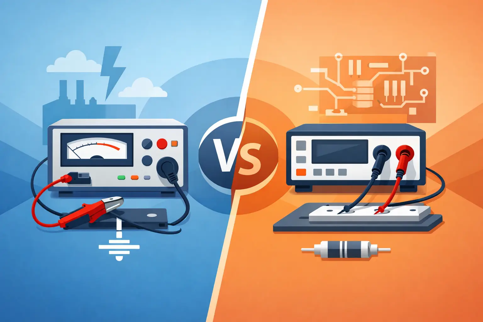
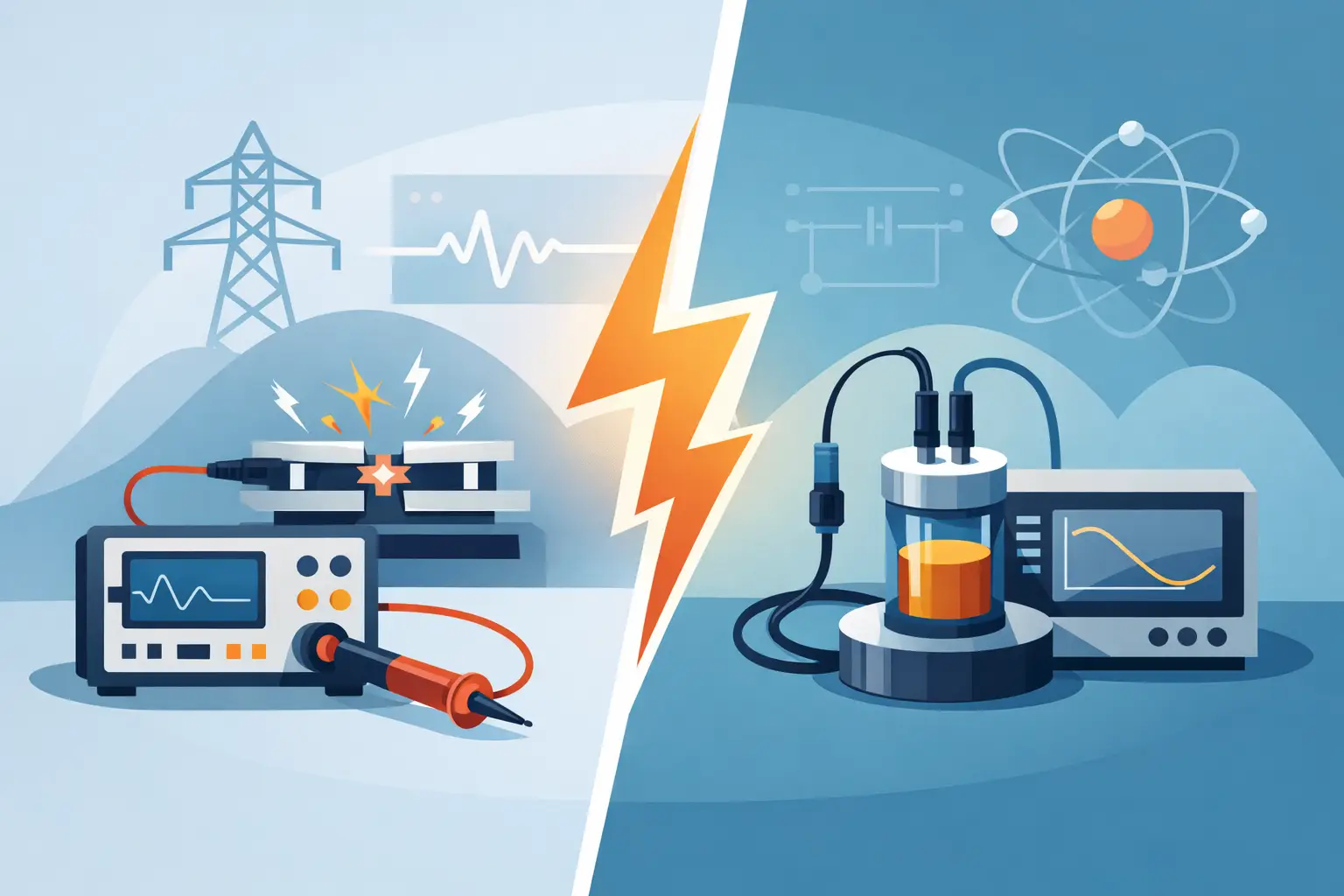
Differentiating Resistive vs. Capacitive Leakage
Resistive and capacitive leakage types are commonly found in many electrical and electronic devices. Both involve leakage currents, but the causes are different. Understanding the differences between resistive and capacitive leakage currents is essential for engineers and technicians conducting Hipot testing. Hipot testers can differentiate resistive and capacitive leakage current. Here are some pointers.
Resistive leakage
This is the unintentional flow of current through a resistive path, often due to insulation degradation or material issues. Resistive leakage is more noticeable at lower voltages and higher temperatures, where the resistance fails to block current flow. Here’s how resistive leakage behaves during testing.
- Voltage-Dependent Behavior: Resistive leakage current shows a linear relationship with applied voltage and follows Ohm’s law (I = V/R). This predictable behavior makes it easier to identify leakage during Hipot testing, as current increases proportionally with voltage.
- Temperature Sensitivity: As insulation materials heat up, their resistance decreases, resulting in increased leakage current. This effect is particularly notable in organic materials, potentially leading to device failure at high temperatures.
- Material-Related Origins: Moisture absorption, carbon tracking on contaminated surfaces, and chemical breakdown of insulating materials, create conductive paths (resistive leakage) that bypasses the insulation barrier.
- Low-Frequency Dominance: Resistive leakage remains constant across frequency ranges, making it the primary concern in DC Hipot testing applications.
Capacitive leakage
This occurs when imperfect insulation allows current to flow across the dielectric material between capacitor plates. Leakage current decreases with higher frequency due to the capacitive effect. Here’s how capacitive leakage behaves during testing
- Frequency-Dependent Response: Capacitive leakage current increases with frequency according to the relationship I = 2πfCV, where f is frequency, C is capacitance, and V is the applied voltage. Frequency dependence is the most reliable method for distinguishing capacitive from resistive leakage during AC hipot testing.
- Dielectric Behavior: The current flowing through the dielectric material between capacitor plates or across insulation barriers, represents the reactive component of the circuit impedance rather than true resistive loss.
- Phase Relationship: Capacitive leakage current leads the applied voltage by 90 degrees in ideal conditions, though real-world dielectric materials introduce some resistive component that reduces this phase angle.
- Field Strength Considerations: In high-energy electric fields, dielectric materials may experience partial breakdown or increased conductivity, resulting in elevated capacitive leakage that can lead to insulation failure.
Acceptable Leakage Current Values by Standard
Here’s a comprehensive breakdown of acceptable leakage current limits across various industries and standards:
| Application Category | Acceptable Limit | Test Conditions | Primary Standards |
|---|---|---|---|
| Standard Consumer Electronics | ≤ 0.5 mA | At line voltage | UL 2089, IEC 60335-1 |
| 3-Prong Plug Products | ≤ 0.75 mA | At line voltage with warning labels | UL 2089 |
| Medical Devices (General) | ≤ 0.1 mA | Patient connection points | IEC 60601-1 |
| Medical Devices (Critical) | ≤ 0.01 mA | Direct cardiac contact | IEC 60601-1 |
| Industrial Equipment (240V) | ≤ 3 mA | Grounded products | UL 508, IEC 60204-1 |
| IT Equipment | ≤ 3.5 mA | Touch current limits | IEC 60950-1, IEC 62368-1 |
| High-Voltage Equipment | Variable | Depends on voltage level | Application-specific standards |

Detailed Application Guidelines
Consumer Electronics and Appliances: Most household products must maintain leakage below 0.5 mA at normal operating voltage. This limit ensures user safety during normal operation and single-fault conditions. Products with enhanced protection (3-prong plugs and warning labels) may have slightly higher limits up to 0.75 mA.
Medical Device Requirements Medical equipment faces the strictest requirements due to patient vulnerability:
- General medical devices: 0.1 mA maximum leakage
- Patient-connected equipment: 0.05 mA for normal conditions, 0.5 mA under single fault
- Cardiac-applied devices: 0.01 mA maximum to prevent microshock
Industrial and Commercial Equipment: Industrial equipment operating in controlled environments may have higher acceptable limits:
- Standard industrial equipment: Up to 3 mA at 240V for grounded products
- Motor drives and controllers: May exceed standard limits with proper protection
- High-power equipment: Custom limits based on risk assessment and protective measures
IT and Telecommunications Equipment : Specific touch current limits:
- Desktop equipment: 3.5 mA maximum touch current
- Pluggable equipment: 0.25 mA for equipment without protective earthing
- Permanently connected equipment: Higher limits with proper installation requirements
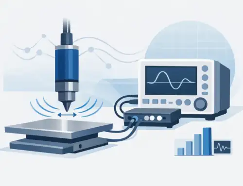
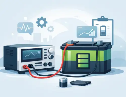
How to Measure Leakage Current Using Hipot Testers
Understanding measurement challenges is crucial. So is the Hipot tester resolution Here are some pointers.
- Tester resolution: Higher resolution can better detect insulation defects early, ensuring compliance, and identifying contamination or micro-defects before they develop into larger issues.
- Milliamp (mA) Resolution: For basic and old industrial equipment 1-10 mA resolution testers may be used.
- Microamp (μA) Resolution: A resolution of 1-100 μA is advised for standard medical and consumer electronics.
- Nanoamp (nA) Resolution: For advanced medical devices and high-end consumer electronics a resolution of 1-100 nA resolution is recommended.
- Picoamp (pA) Resolution: A resolution of 1-1000 pA is recommended for ultra-high precision medical devices and equipment used in research & development.
- Filtering capacitive charge current: Filtering techniques like low-pass, narrow-band, time-base, frequency-based, or vector analysis help isolate and accurately measure leakage current and differentiate it from capacitive charging current.
- Capacitive current filtering: When voltage is applied, capacitive charging can create a current flow that exceeds the actual leakage current. A reliable Hipot tester can differentiate true leakage (e.g., 10 nA) from capacitive charging (e.g., 5 μA).
Common Causes of Excess Leakage and How to Fix Them
- Contamination: Insulation surfaces may be contaminated with dust, moisture, or foreign materials on insulation surfaces. This can be fixed by cleaning contaminants and moisture from the insulation surfaces.
- Insulation Degradation: This may be age-related deterioration of insulation materials. Here, you may need to replace the worn or faulty components.
- Manufacturing Defects: These may be caused by inadequate insulation thickness or poor material quality. You may have to modify the design for better insulation systems and improved performance.
- Environmental Factors: High humidity or temperature can affect insulation properties. Check the device features and insulation materials to see if they work well in certain environmental conditions.
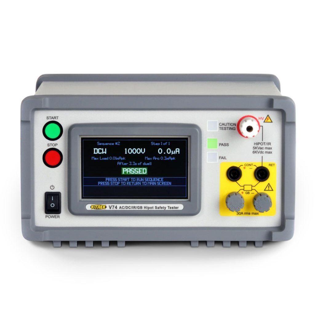
How Vitrek Testers Handle Leakage Current Measurement
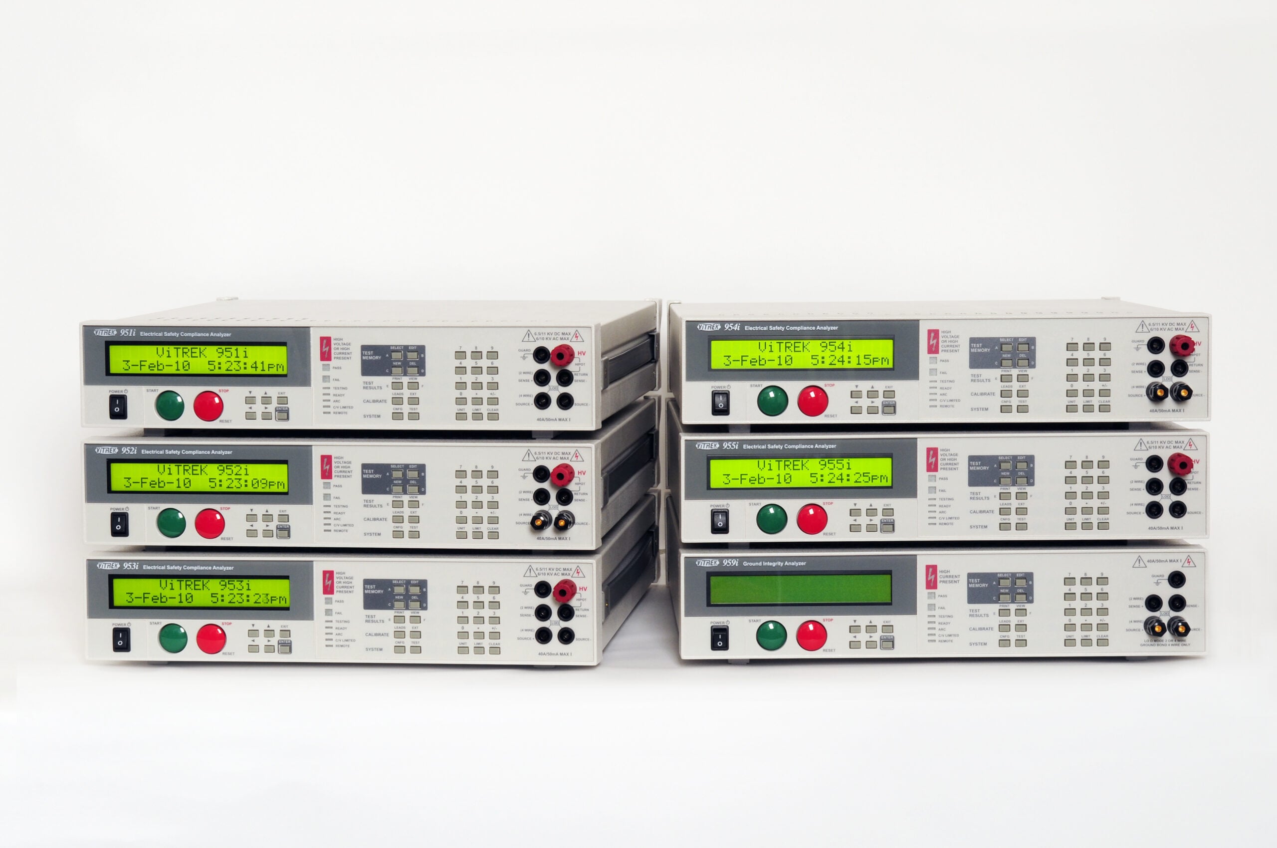
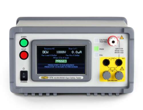
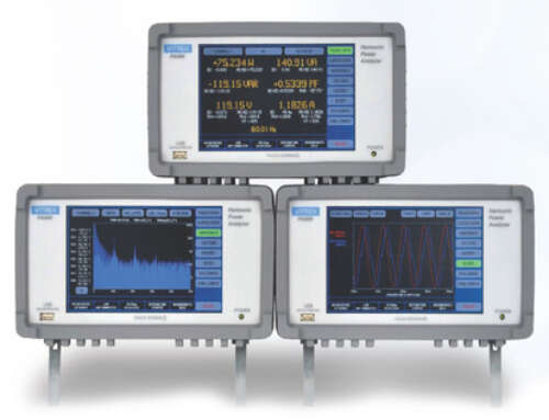
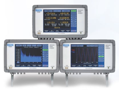
Vitrek’s V7X and 95X Series hipot testers are specifically engineered to address the complex challenges of accurate leakage current measurement and ensure compliance with international safety standards.
Key Technical Capabilities
High-Resolution Measurement
- Leakage current resolution down to 100 picoamps
- Wide dynamic range accommodates both high and low leakage applications
- Advanced analog-to-digital conversion for precision measurements
Advanced Signal Processing
- Proprietary arc detection algorithms prevent false trips
- Multi-stage filtering eliminates capacitive charging artifacts
- Real-time analysis of resistive vs. capacitive components
- Automatic compensation for cable and fixture capacitance
Comprehensive Test Capabilities
- AC/DC output voltages up to 30 kV
- 4-wire milliohm measurement for contact resistance
- Insulation resistance (IR) testing mode
- Automated test sequences with programmable limits
Compliance and Documentation
- Pre-configured test profiles for major international standards
- QT Insite software for automated testing and comprehensive reporting
- Data logging and traceability for quality assurance
- Integration with manufacturing execution systems (MES)
Ready to Elevate Your Electrical Safety Testing?
The distinction between acceptable and dangerous leakage currents often comes down to having the right measurement tools and expertise.
With Vitrek’s precision hipot testers, technicians can:
- Avoid false failures due to capacitive charging artifacts
- Detect subtle insulation breakdowns before products reach customers
- Confidently meet IEC, UL, ISO, and FDA standards
- Reduce compliance costs through efficient, accurate testing
Don’t let inadequate leakage current measurement put your products, customers, or business at risk. Contact Vitrek’s technical experts today for a consultation on your specific testing requirements, or request a demonstration to see how our advanced measurement capabilities can enhance your quality assurance process and ensure regulatory compliance.


