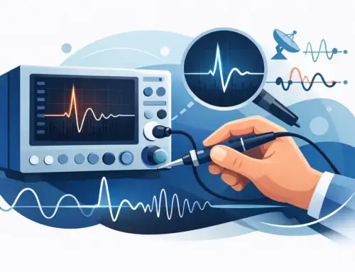
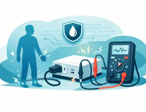
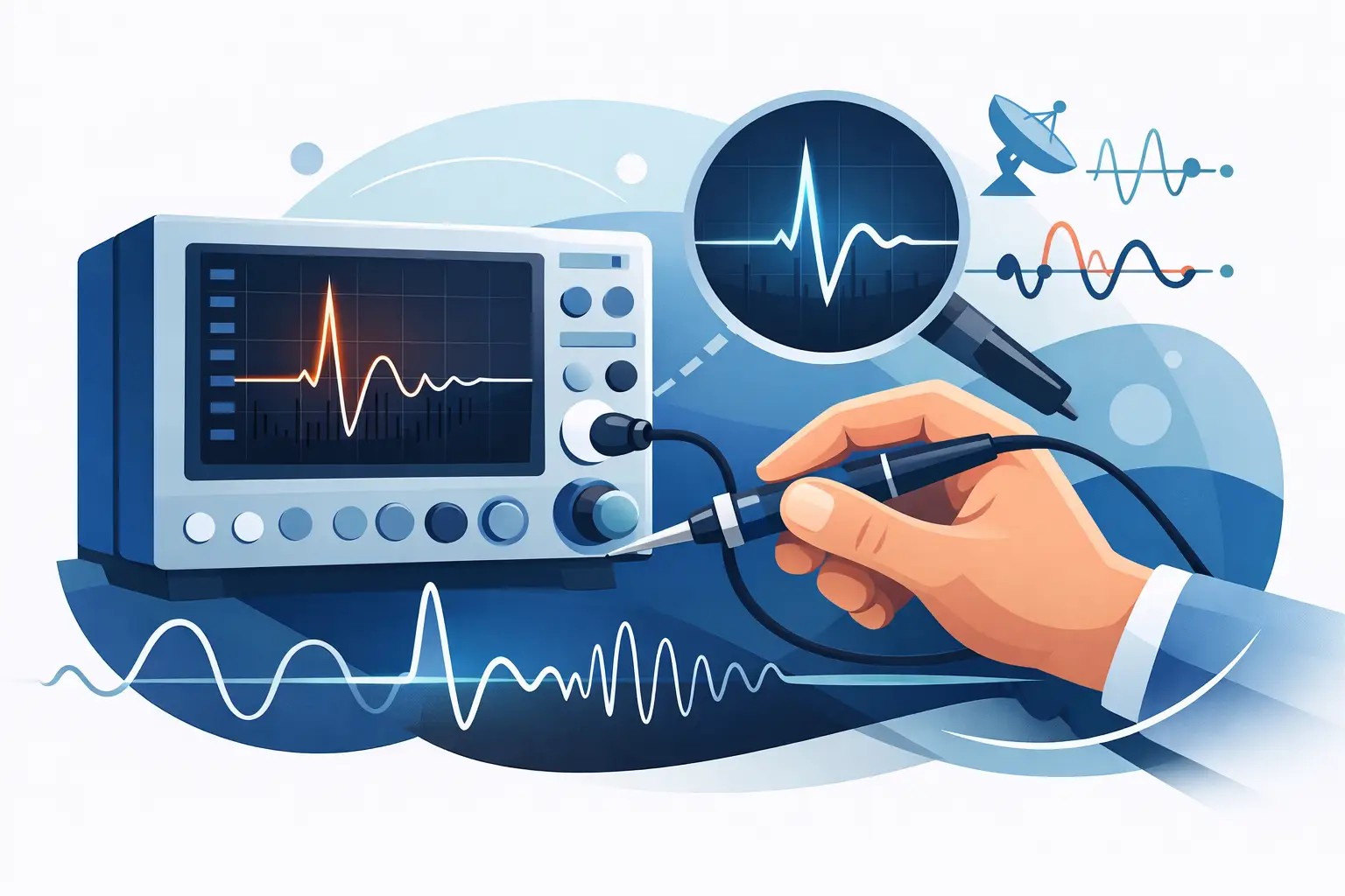
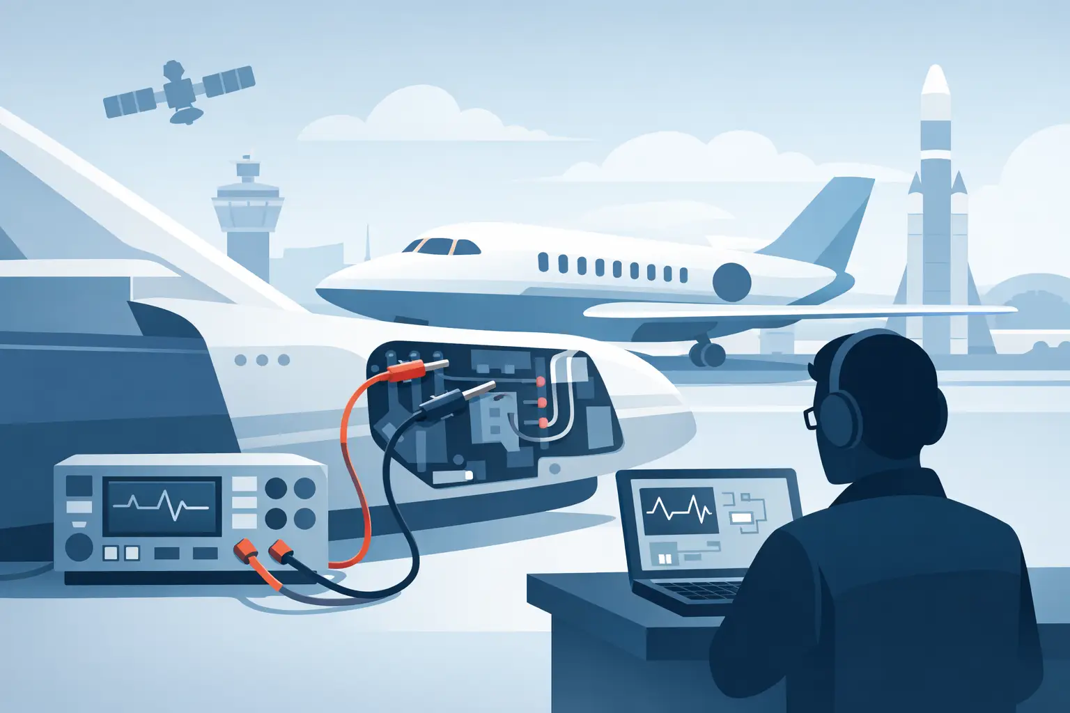
Vibration analysis is crucial in engine testing. It identifies issues, such as imbalance, misalignment, and wear. Whether testing jet engines, gas turbines for power generation, or APUs, a proper vibration analysis setup is vital for ensuring safety, performance, and reducing maintenance costs. Test cells simulate operational conditions. Accurate vibration analysis detects faults like rotor imbalance and bearing issues before failures occur, ensuring safe operation and minimized downtime. However, environmental factors such as electromagnetic interference, temperature variations, and structural noise can compromise measurement quality.
This guide outlines best practices for effective vibration analysis, including sensor placement, cable management, and EMI mitigation.

Fundamentals of Engine Test Cell Vibration Measurement
Before beginning sensor installation, it’s crucial to understand the sources of vibration in engines. Each generates a distinct vibration pattern, providing valuable insight into the engine’s internal conditions.
- Imbalance: An imbalance occurs when the distribution of mass around a shaft is uneven, causing centrifugal forces that create vibrations that vary with the shaft’s rotational frequency. At high speeds even small imbalances, like in a gas turbine spinning at 15,000 RPM, generate significant forces, leading to excessive vibrations.
- Misalignment: When connected shafts are not aligned along the same axis, they can generate forces at twice the rotational frequency and higher harmonics. The resulting axial and radial vibrations lead to premature bearing wear and elevated vibration levels in engines.
- Combustion Irregularities: In gas turbines and piston engines, uneven combustion creates cyclic pressure pulses and structural vibrations at firing frequencies. These irregularities produce unique patterns in the vibration spectrum, highlighting specific combustion issues in engines.
- Gear Mesh Frequencies: These are high-frequency vibrations corresponding to the number of gear teeth multiplied by shaft speed. Worn or damaged gears, improper backlash, and tooth damage create sidebands around these frequencies, offering diagnostic insights into gear health.
- Bearing Defects: Bearing defects create vibrations at characteristic frequencies that are defined by the type of defect, such as outer race, inner race, or rolling element. Defects like these produce high-frequency impacts modulated by lower-frequency shaft vibrations, which can be used to identify bearing wear or damage.
- Resonance Amplification: When the excitation frequency matches a structural natural frequency, the result is amplified vibration resonance. Test cell structures, fixtures, and piping systems can resonate, complicating vibration measurements and potentially masking true engine-related vibrations.
Key Measurement Parameters
Comprehensive vibration characterization requires quantification of three fundamental parameters:
- Vibration Amplitude: The amplitude of the vibration indicates the vibration severity. The vibration amplitude is usually measured as a displacement (mils), velocity (inches/second), or acceleration (Gs). Engine OEMs typically use a specific set of amplitude units to specify operational limits.
- Rotor Speed: The rotational speed, or frequency, of the rotors in the engine are necessary for identifying the source of vibration. Vibrations that occur at the frequency of a specific rotor, for example the fan or the low-pressure turbine, indicate imbalance. Vibrations at other frequencies may indicate issues with accessories, bearings or gears. Order analysis, which expresses frequencies as multiples of shaft speed, facilitates the tracking of speed-dependent phenomena during tests.
- Phase Angle: Phase angle measures the timing relationship between vibration signals and a reference mark on the shaft. It is critical for balancing operations. Different phase angles across measurement points highlight where to add or remove weight. Phase differences can also help distinguish between imbalance (consistent phase) and misalignment (variable phase).
Sensor Selection for Engine Test Environments
Your sensor choice for vibration analysis depends on the environment and measurement requirements.
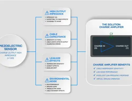
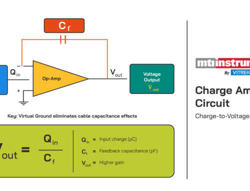
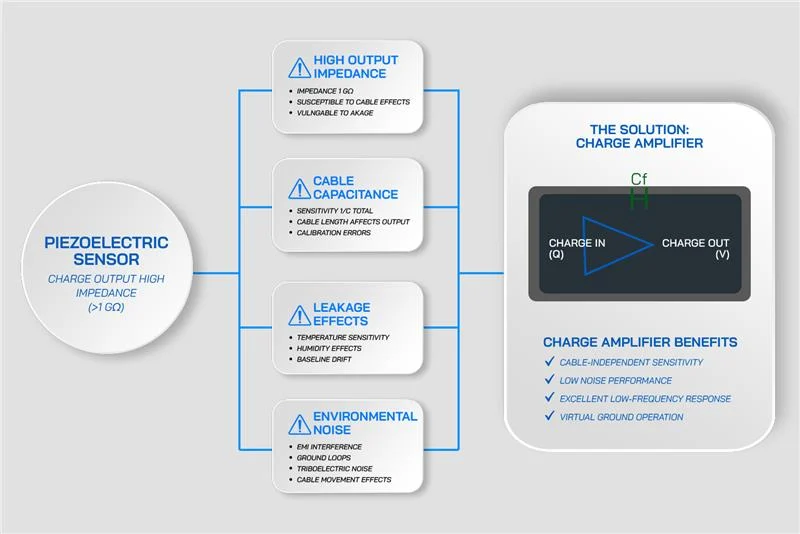
- Charge-mode Piezoelectric Accelerometers: These are sensors that utilize piezoelectric crystals to generate an electrical charge proportional to the acceleration. They can perform across a wide temperature range, some exceeding 600°F, making them ideal for high-temperature zones near turbines and combustion chambers. They require external charge amplifiers to convert high-impedance charge signals into low-impedance voltage signals, which are suitable for long cable runs and data acquisition systems.
- ICP/IEPE Accelerometers: These feature built-in electronics that perform impedance conversion internally. Because IEPE sensors only require a two-wire connection that carries both signal and sensor power, installation is relatively simple. These accelerometers work well for general-purpose monitoring in moderate-temperature environments.
Note: High-temperature zones near turbines (exceeding 175°C) should always use charge-mode accelerometers. To ensure these sensors provide reliable data, signal conditioning is essential. Charge amplifiers such as the MTI 55CA convert charge signals into readable voltage and are designed to handle long cable runs, ensuring that your vibration data remains accurate. It is important to install the charge amplifier as close to the sensor as possible.
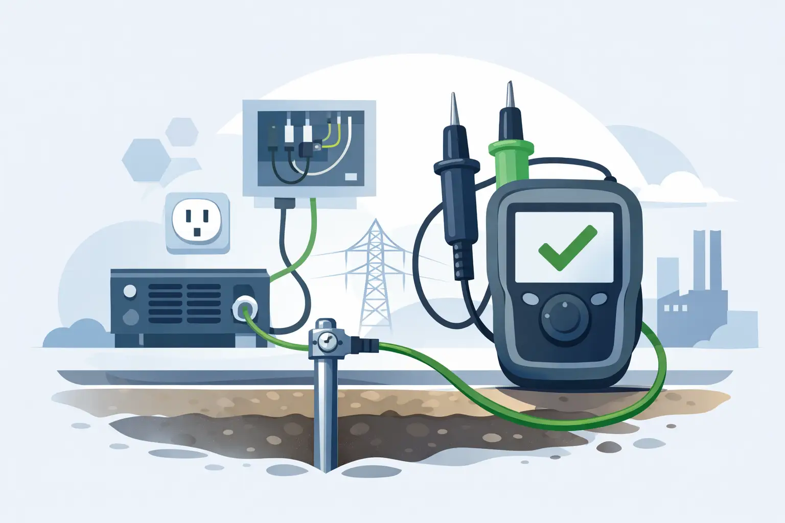
Block Diagram of wiring from jet engine to PBS-4100R+

Test Cell Design for Accurate Vibration Data
Your engine test cell setup plays a crucial role in obtaining reliable vibration data. Key design elements to consider include:
- Structural Isolation and Damping: Vibration-isolated test stands with elastomeric or pneumatic isolators prevents the structure-borne engine noise transmission to the test cell foundation. This isolation minimizes cross-contamination between engine vibration and building structural modes, ensuring that measurements accurately represent engine dynamics rather than facility resonances.
- Cable Routing: Proper cable routing minimizes electromagnetic and triboelectric interference in engine test cell vibration analysis. Use shielded, low-noise cables with semiconductive jackets to suppress triboelectric charge. Maintain a 0.3-meter separation between sensor cables and high-current conductors to prevent EMI. Secure cables regularly to reduce motion-induced noise. For cable runs over 15 meters, MTI 55CA charge amplifiers ensure signal integrity with ultra-high input impedance and low-noise amplification.
- Grounding and Shielding: Proper grounding of charged amplifiers and data acquisition systems (DAQ) is crucial. Ground loop currents that cause low-frequency noise in vibration signals should be eliminated. Single-point grounding establishes a reference ground at the DAQ system. Terminating the sensor shields at the same place prevents multiple current paths. Equipotential bonding ensures common ground potential across test stands, engine mounts, and instrumentation, minimizing circulating currents and reducing noise for accurate measurements.
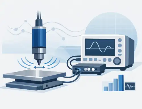
Sensor Placement and Mounting Techniques
Accurate sensor placement is crucial for obtaining reliable data during vibration analysis. Here are the steps to follow for accurate sensor positioning.
- Critical Measurement Locations: Place sensors at bearing housings, casing sections, gearbox interfaces, and mounting points to detect imbalance, misalignment, bearing wear, and aerodynamic excitation. Positioning sensors near bearing centerline enhances sensitivity to rotor dynamics.
- Mounting Methods: Accelerators can be mounted using stud mounts, adhesives, and magnetic bases. Stud mounting offers the best frequency response for permanent installations. Adhesive mounting provides a good balance for lower frequencies, while magnetic base mounting is ideal for temporary setups with limited bandwidth.
- Sensor Orientation: Align accelerometers with vibration directions, radial for imbalance, axial for thrust bearing condition, and tangential for torsional vibrations. Triaxial accelerometers enable three-axis measurement but may exhibit cross-axis sensitivity in high-vibration environments.
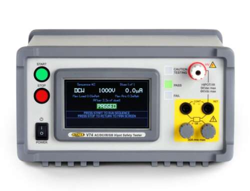
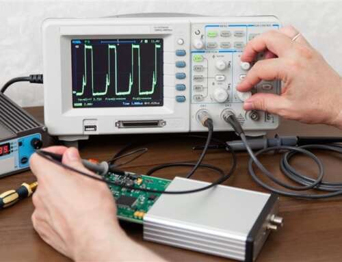
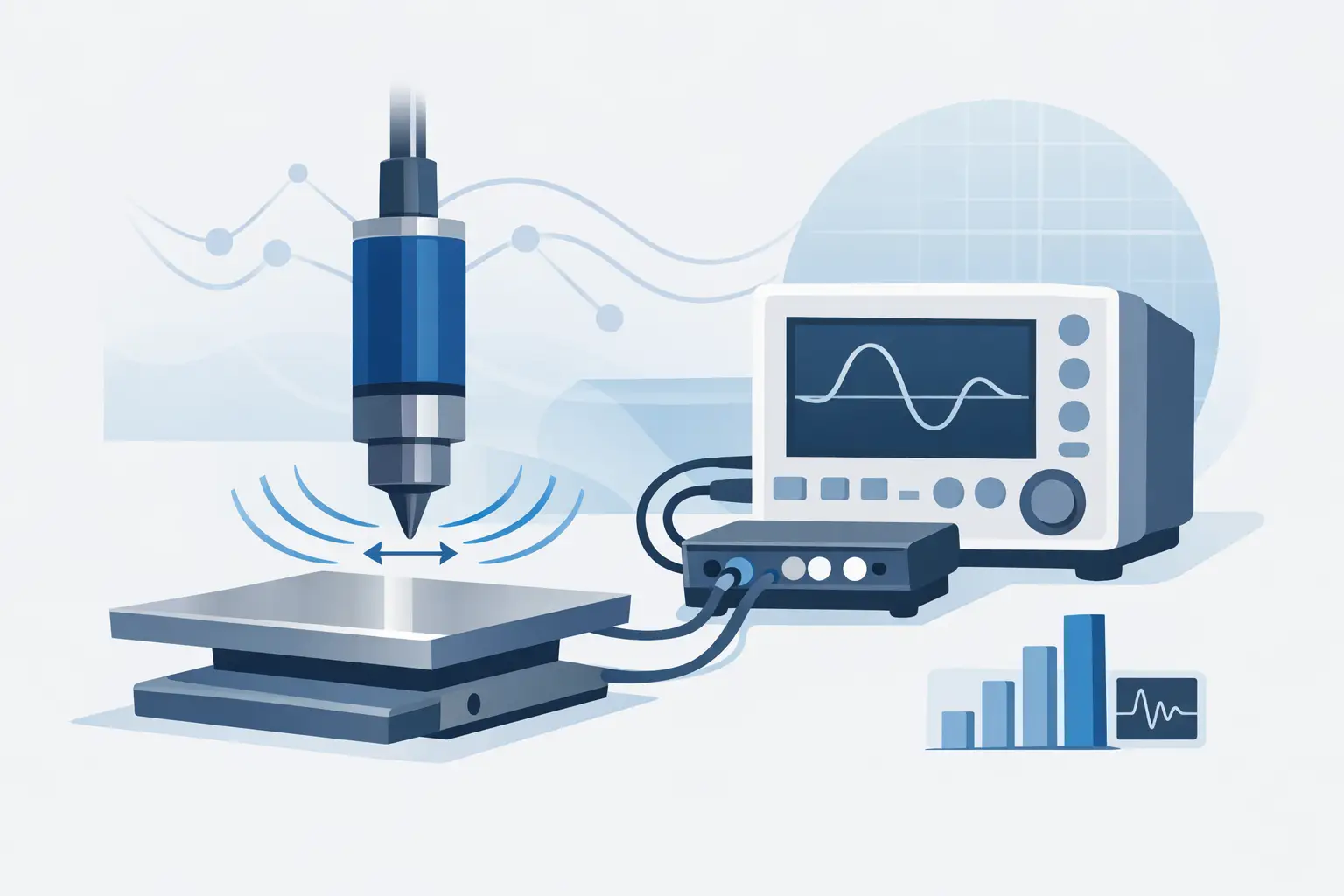
- Pre-Test Calibration Verification: Before initiating test sequences, verify the measurement chain integrity using calibrated excitation sources. Vitrek’s The MTI 1510A signal generator provides precision voltage outputs to validate charge amplifier gain settings and DAQ system scaling.


Signal Conditioning and Data Acquisition Best Practices
Proper signal conditioning represents the critical interface between piezoelectric sensors and digital acquisition systems. This is where many test cell setups fall. The high-impedance signals produced by charge-mode accelerometers degrade rapidly over long cable runs. Without proper shielding and conditioning, you get noise, drift, and inaccurate measurements.
The signal conditioning challenges:
- Charge-mode sensors output high-impedance signals that are extremely vulnerable to cable capacitance and electromagnetic interference
- The significant signal degradation and noise pickup that occur in long cable runs
- Environmental factors like temperature variations cause baseline drift
- How to provide the proper signal proper conditioning to prevent your vibration data from becomes unreliable or completely unusable
MTI Charge Amplifier Solutions
- Vitrek’s MTI 55CA charge amplifiers handle long cable installations particularly well. transforming high-impedance charge signals into low-impedance voltage signals that travel cleanly to your data acquisition system.
- Variable gain settings let you adjust the amplification level to match your vibration amplitude and ADC input specifications, ensuring signals are neither too small (buried in noise) nor too large (causing clipping and distortion).
- Built-in high-pass and low-pass filters remove unwanted frequency content, where high-frequency electronic noise above your measurement range gets eliminated before it can create false signals through aliasing
- The MTI 41CA and CA1800 series both provide synchronized signal processing for comprehensive engine monitoring. They provide options for different channel counts and integration requirements.
Pre-Test Calibration Protocol
- Use the MTI 1510A signal generator to verify your entire measurement chain before testing begins.
- Apply a known signal at the amplifier input and confirm you get the expected output at the data acquisition system.
- This catches cabling problems, amplifier drift, and DAQ configuration errors before you invest time in engine testing.
- Document baseline calibration values for comparison after testing to detect any system drift.
Optimizing Your Data Acquisition Setup
- Set your sampling rate based on the engine’s maximum speed and the harmonics you need to capture
- As a rule, sample at least 2.5 times your highest frequency of interest to avoid aliasing
- For engines running to 10,000 RPM with 10th-order harmonics, you need substantial bandwidth, approximately 4 kHz minimum
- Configure anti-aliasing filters in your charge amplifiers or DAQ system to prevent high-frequency noise from folding back into your measurement band
- Adjust gain settings so peak vibration signals use 60-80% of your ADC range, providing headroom for transients while maintaining resolution
Data Analysis and Diagnostic Techniques
Extracting actionable intelligence from engine test cell vibration analysis requires systematic processing techniques:
Time-Domain Analysis
- Shows overall vibration levels as amplitude versus time
- Reveals transient events like startup resonances, impacts, or sudden changes in operating conditions
- Provides RMS (root mean square) values that quantify overall vibration energy
- Helps you spot sudden changes or anomalies that might not be obvious in frequency analysis
- Useful for comparing vibration levels against acceptance criteria or baseline measurements
Frequency-Domain Analysis
- Uses Fast Fourier Transform (FFT) to convert time signals into frequency spectra
- Reveals individual frequency components and their amplitudes—each peak tells you about a specific vibration source
- Identifies which components (imbalance, misalignment, gear mesh) contribute most to overall vibration
- Enables you to track how specific frequencies change over time or operating conditions
- Creates spectral maps that become your diagnostic fingerprint for engine condition
Order Tracking for Variable-Speed Testing
- Locks your analysis to shaft speed rather than fixed frequencies
- Makes it easier to identify speed-dependent phenomena like imbalance and gear mesh during run-up or coast-down
- Presents data as orders (1×, 2×, 3× shaft speed) instead of Hz, simplifying interpretation
- Particularly valuable when testing engines through their full operating range
- Eliminates the smearing effect that occurs when analyzing variable-speed data with standard FFT
Phase-Based Balancing
- Relies on accurate phase measurements between a once-per-revolution reference and your vibration signal
- The PBS-4100R Plus system provides precise phase data that enables single-plane and two-plane balancing corrections
- Phase angle tells you where to place correction weights—not just how much weight you need
- Reduces trial-and-error balancing, saving time and reducing wear on test equipment
- Enables you to balance rotors to tight tolerances in minimal runs
Key Diagnostic Indicators to Monitor
- Increased 1× vibration at rotational frequency suggests an imbalance or a shift in mass distribution
- Elevated 2× levels of rotational frequency often indicate misalignment, bent shaft, or mechanical looseness
- Broadband noise increases across multiple frequencies in signals bearing wear or developing surface damage
- Sub-synchronous frequencies, below shaft speed, point to oil whirl, fluid instability, or rub conditions
- High-frequency spikes indicate bearing defects, gear tooth damage, or impacts from loose components
Trend Monitoring Over Time
- Track vibration amplitudes across multiple test runs to identify gradual degradation
- Establish baseline measurements for new or newly serviced engines
- Set alarm thresholds based on statistical analysis of normal operating data
- Compare current spectra to historical data to detect subtle changes before they become problems
- Document vibration trends to support predictive maintenance decisions and warranty analysis
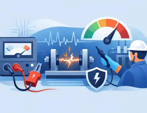
Safety, Maintenance, and Calibration Protocols
Ensuring safety, reliability, and accuracy in engine test cells depends on following the right safety measures, maintenance routines, and calibration protocols. Here’s what you need to keep in mind:
- Always use physical barriers to protect personnel from rotating engine parts, especially during high-RPM tests. These barriers should be placed around the test area to ensure safe operation.
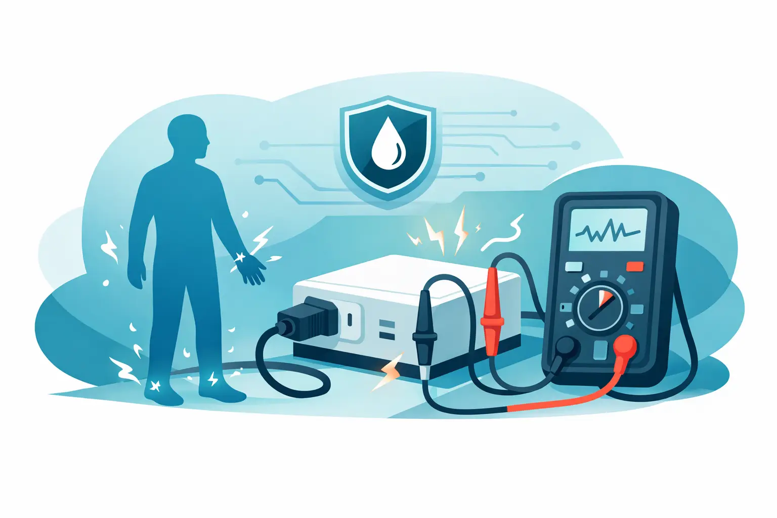
- Secure all sensor cables to avoid tripping hazards or interference with test equipment. Ensure cables are shielded to prevent EMI and minimize signal disruptions.
- Always monitor engine performance in real-time, especially during high-speed tests. Use vibration monitoring tools to detect potential issues early and shut down the test if necessary.
- Calibrate accelerometers before each test cycle to verify accuracy. This step ensures that sensors are measuring vibrations correctly and helps prevent false readings.
- Regularly calibrate charge amplifiers (such as the MTI 55CA) to maintain their performance. This ensures consistent signal conditioning and reliable data collection throughout testing.
- Inspect sensor mounts for any signs of wear or damage, such as loose connections or degraded adhesive. Secure any loose parts to prevent inaccurate readings.
- Regularly check the DAQ system inputs and connections to ensure they’re functioning properly. This includes verifying cable connections and cleaning connectors to avoid signal interference.
Case Example: Optimizing Turbine Engine Vibration Measurement
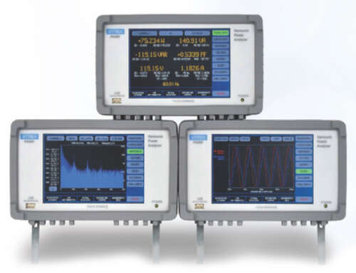
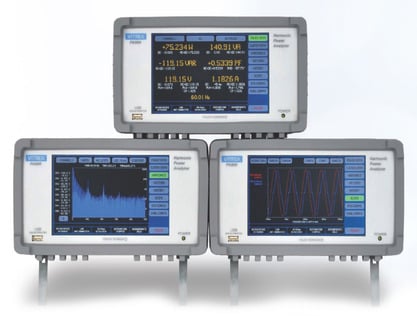
In turbine engine maintenance, precise vibration analysis is crucial for identifying imbalances that can lead to premature wear or failure. MTI Instruments’ PBS-4100+ system exemplifies an effective solution for this challenge. This vibration analyzer is a powerful tool for turbine engine maintenance. By performing vibration surveys across different engine speeds, it identifies imbalances in engine spools. The system analyzes vibration data using tracking filters, isolating specific frequencies to pinpoint the source of the imbalance. Once detected, it calculates the corrective weight placement to restore balance. This process enhances engine performance, reduces downtime, and extends lifespan. The PBS-4100+ offers an intuitive interface, making turbine balancing accessible even to technicians with limited experience. With its precision and ease of use, it ensures more efficient, cost-effective engine maintenance.
Explore how MTI’s charge amplifiers and PBS-4100+ systems enhance vibration accuracy and balancing efficiency in engine test cell environments. Visit MTI Instruments Turbine Balancing & Vibration Analysis to discover precision measurement solutions engineered for demanding test cell applications.


