A failed EMC check rarely starts with a dramatic waveform. More often, it begins with a motor drive, inverter, or switched-mode supply that appears stable under average power measurements but carries distortion that changes heating, efficiency, and compliance results. That is where a harmonic measurement power analyzer becomes necessary. It shows not only how much power a device consumes or delivers, but how waveform content across harmonic orders affects real performance.
For engineering teams working in EV power electronics, aerospace systems, industrial drives, medical equipment, or appliance validation, harmonic data is not a secondary metric. It directly affects pass-fail decisions, thermal behavior, filter design, and grid interaction. If the analyzer cannot resolve harmonics accurately under real operating conditions, the resulting decisions can be expensive.
What a harmonic measurement power analyzer actually measures
A harmonic measurement power analyzer captures voltage and current waveforms, then computes the frequency components that ride on top of the fundamental. In practical terms, it separates the 50 Hz or 60 Hz base signal from the higher-order content caused by nonlinear loads, switching devices, and control electronics.
That matters because real systems are rarely sinusoidal. Variable frequency drives, onboard chargers, DC-AC inverters, LED drivers, UPS systems, and laboratory power converters all generate distortion to some degree. Basic meters may report RMS values and average power acceptably, yet miss the harmonic structure that explains overheating, neutral current issues, transformer stress, poor power factor, or failed standards testing.
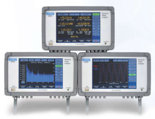
A capable analyzer typically reports harmonic amplitude by order, total harmonic distortion, phase relationships, real and reactive power, crest factor, and frequency. More advanced instruments also support interharmonic analysis, wide bandwidth capture, transient observation, and synchronized multi-channel measurement so engineers can correlate distortion with switching events and load transitions.
Why harmonic accuracy is harder than it looks
On paper, harmonic analysis sounds straightforward: sample the waveform, run a transform, and display the results. In actual test environments, accuracy depends on much more than algorithm choice.
Front-end design matters first. Voltage and current inputs must maintain linearity across a wide dynamic range, especially when a small harmonic component sits on top of a large fundamental signal. If the instrument front end introduces error, the displayed harmonic content may reflect analyzer limitations rather than DUT behavior.
Bandwidth also matters. Higher-order harmonics, fast edge content, and inverter-driven waveforms can extend far beyond what a low-bandwidth instrument resolves cleanly. If the analyzer rolls off too early, the measured harmonic spectrum looks cleaner than reality. That may be acceptable for utility-grade low-order analysis, but it is not acceptable for R&D work on high-frequency conversion stages.
Timing and synchronization are another common issue. Harmonic calculations depend on stable sampling and appropriate windowing relative to the signal frequency. In variable-speed or frequency-agile systems, an analyzer must track changing fundamentals without smearing the spectrum. This becomes especially important when testing motors, aircraft power systems, and EV platforms that do not stay fixed at one operating point.
Noise immunity is the final piece. In production or lab environments with high common-mode voltages and fast switching edges, poor noise rejection can corrupt low-level harmonic readings. Engineers should not treat harmonic numbers as trustworthy unless the instrument architecture supports the environment in which it is deployed.
Where a harmonic measurement power analyzer fits in the lab and on the line
In research and development, the instrument helps engineers understand how design choices affect efficiency, thermal margin, and compliance headroom. A power stage may meet output targets while still producing harmonic content that forces a redesign of filtering, magnetics, or control loops. Early visibility reduces rework.
In validation and compliance workflows, harmonic analysis supports standards-driven testing where waveform quality is part of acceptance. The exact standard depends on the application, but the underlying requirement is consistent: the measurement system must provide traceable, repeatable data that stands up during audits, certification review, and customer scrutiny.
In manufacturing, the use case shifts slightly. Engineers are often less concerned with exhaustive spectral interpretation and more focused on repeatable pass-fail thresholds, cycle time, and correlation across stations. Here, the best analyzer is not simply the one with the deepest feature set. It is the one that combines accuracy with speed, stable automation, and predictable behavior across shifts and sites.
Key specifications that deserve scrutiny
When evaluating a harmonic measurement power analyzer, start with basic power accuracy, but do not stop there. Harmonic performance is shaped by the entire signal chain.
Frequency bandwidth should match the actual spectrum of the application, not the nominal line frequency. This is a frequent mismatch in inverter and high-speed switching applications. If the DUT generates meaningful content well above low-order harmonics, the analyzer must be able to capture it without excessive attenuation or aliasing.
Sampling architecture is equally important. Engineers should look at sampling rate, synchronization method, and whether all channels are acquired simultaneously. Multiplexed approaches can create phase or timing errors that are unacceptable in dynamic multi-phase systems.
Current transducer compatibility also deserves attention. The analyzer may be excellent, but if the current sensor lacks bandwidth, phase accuracy, or low-current resolution, the total measurement result will still be wrong. The system should be considered as an analyzer-plus-sensor measurement chain.
Crest factor handling is another practical issue. Distorted current waveforms often contain sharp peaks. Instruments that perform well on smooth sine waves may show degraded accuracy when the waveform crest factor rises. This affects switch-mode supplies, rectifier inputs, and pulsed loads.
Finally, review data interface and automation support. Many teams now need harmonic data integrated into production software, design validation scripts, or long-duration test systems. SCPI command support, software drivers, logging capability, and deterministic remote control are not minor conveniences. They shape how usable the instrument will be after purchase.
Application examples where the data changes decisions
In EV and hybrid powertrain development, engineers use harmonic analysis to examine onboard chargers, traction inverters, and auxiliary power systems. Efficiency maps alone do not tell the whole story. Harmonic current can influence thermal stress, EMI mitigation strategy, and upstream power quality impact.
In aerospace and defense, waveform fidelity is tied to platform reliability and standards compliance. Aircraft and mission systems often operate under nonstandard frequencies, dynamic loads, and tightly controlled power budgets. Harmonic behavior can reveal integration issues that average measurements miss.
In appliance and consumer electronics testing, nonlinear loads create distortion that affects compliance and real-world energy behavior. Engineers may need to distinguish whether a failing result is caused by product design, test setup, or measurement limitations. A higher-grade analyzer shortens that troubleshooting cycle.
Medical device and laboratory instrumentation teams face a different constraint: confidence. If a device must operate safely and predictably around sensitive electronics, inaccurate harmonic characterization introduces avoidable risk. This is where calibration traceability and known uncertainty budgets matter as much as the display itself.
Common mistakes when selecting an analyzer
One common mistake is buying for nominal voltage and current range alone. That approach ignores waveform complexity, bandwidth needs, and the reality of transients. It works until the first distorted load is tested seriously.
Another is assuming that all FFT-based harmonic functions are equivalent. They are not. Instruments vary significantly in front-end accuracy, spectral resolution, anti-alias filtering, and frequency tracking. Two analyzers may produce very different results on the same inverter output, especially at higher harmonic orders.
A third mistake is separating compliance needs from engineering needs. In many organizations, one instrument is expected to support design work, troubleshooting, formal reporting, and production transfer. If the analyzer cannot bridge those workflows, teams often end up maintaining multiple tools and reconciling conflicting datasets.
For that reason, many technical buyers prefer a manufacturer with experience in precision power measurement, calibration discipline, and support for regulated environments. For organizations that need engineering-grade results across R&D and production, that combination is usually more valuable than a long feature list.
Choosing for the job, not the brochure
The right analyzer depends on what you are trying to prove. If the task is utility-side low-order harmonic verification, requirements may be modest. If the task is characterizing a wide-bandgap inverter, switched power converter, or multi-phase dynamic load, the instrument needs significantly more from its analog front end, timing system, and software control.
A serious evaluation should include representative waveforms, not just datasheet comparison. Test the analyzer on the loads you actually build, certify, or troubleshoot. Compare harmonic stability over time, behavior at low power factor, and correlation with known references. If the instrument will be automated, verify command response and repeatability before deployment.
Vitrek serves teams that cannot afford measurement ambiguity in those environments. When harmonic data influences design release, compliance evidence, or production yield, the analyzer is not just another bench instrument. It becomes part of the decision chain.
The best time to identify harmonic measurement limits is before they shape a design review, a certification delay, or a field failure.


