A piezoelectric accelerometer generates a tiny electrical charge when it vibrates. That charge, measured in picocoulombs, contains valuable information about machinery health, structural integrity, or performance characteristics. But here’s the problem: you can’t measure it reliably without proper signal conditioning.
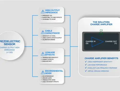
One of the fundamental challenges lies in the nature of the signal itself: high-impedance charge outputs generated by piezoelectric sensors versus the low-impedance voltage signals required by data acquisition systems and analyzers. Without proper signal conditioning, even the most accurate accelerometer can produce distorted, noisy, or unstable results. This creates a challenge for engineers working with vibration measurement systems. In vibration and dynamic testing, accelerometer signal conditioning determines whether the measured data accurately reflects the physical behavior of the system.
This guide explains the complete accelerometer signal conditioning process, from the physics of charge generation to practical implementation in industrial and aerospace environments. You’ll learn how charge amplifiers work, why proper conditioning prevents measurement errors, and how to select the right approach for your application.
Understanding the Piezoelectric Accelerometer Signal and Its Challenges
Piezoelectric accelerometers rely on crystalline materials that generate an electrical charge when subjected to mechanical stress. When the sensor experiences acceleration, the piezoelectric element produces a direct charge proportional to the applied force.
Unlike voltage-output sensors, the raw output of a charge accelerometer is:
-
- A high-impedance electrical charge
- Typically specified in pico-coulombs per g (pC/g)
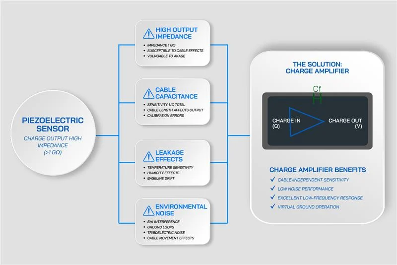
Charge signals present several inherent challenges:
- High impedances allow voltage leakage through insulation resistance, causing low-frequency drift.
- Cable capacitance attenuates signal amplitude and introduces phase errors.
- Triboelectric noise, generated by cable motion, can mask low-level vibration signals.
- Environmental factors such as humidity and contamination degrade insulation performance.
These effects tend to become more pronounced with longer cable runs and harsh environments, exactly the conditions where charge accelerometers are often used. These signal characteristics explain why accelerometer signal conditioning is essential when working with high-impedance charge outputs.
What Is Accelerometer Signal Conditioning?
Accelerometer signal conditioning converts the raw electrical output from your sensor into a stable voltage signal suitable for measurement and analysis.
The process includes several functions:
- Charge-to-voltage conversion transforms picocoulombs into millivolts using a charge amplifier circuit.
- Impedance transformation converts the high-impedance charge signal into a low-impedance voltage signal that resists cable effects and interference.
- Gain adjustment scales the voltage to match your data acquisition system’s input range, maximizing resolution without overload.
- Integration converts acceleration to velocity or displacement when your application requires it, common in balancing and modal analysis.
- Filtering removes unwanted frequency content through anti-aliasing filters, high-pass filters that eliminate drift, and low-pass filters that reject high-frequency noise.
The objective is straightforward: preserve the true amplitude and phase information while reducing noise and drift. Poor signal conditioning introduces errors that post-processing cannot reliably correct. Proper conditioning ensures the voltage signal entering your analyzer accurately represents the vibration at the sensor location.
Charge Mode vs. ICP (IEPE) Accelerometers
Both charge mode and ICP®/IEPE accelerometers rely on piezoelectric sensing elements, but they differ significantly in signal handling. Understanding the differences helps you choose the right sensor and conditioning approach for your application.
- Charge Accelerometers: These accelerometers output high-impedance charge signals measured in picocoulombs. They require external charge amplifiers for signal conditioning, giving engineers flexibility in gain, filtering, and integration. These sensors operate across very wide temperature ranges, with certain charge accelerometer designs exceeding 500°C, making them essential for aerospace, turbine, and high-temperature applications. These accelerometers are sensitive to cable effects, making proper shielding and signal conditioning essential. The frequency range extends from near-DC to hundreds of kilohertz, depending on sensor design and conditioning.
- ICP/IEPE Accelerometers: These accelerometers contain built-in electronics that perform impedance conversion internally, thereby simplifying the setup. They output low-impedance voltage signals, typically in millivolts. These sensors require constant-current power, usually 2-20 mA at 18-30 VDC, supplied through the same two-wire cable that carries the signal. These accelerometers have lower temperature limits, typically below 125°C, because the internal electronics can’t survive extreme heat. They have much lower cable sensitivity than charge mode sensors. The frequency range is limited by built-in AC coupling, which blocks DC and very low frequencies. All these features make them ideal for general industrial vibration applications, limiting their performance in extreme environments.
Charge-to-Voltage Conversion Fundamentals
How does a charge amplifier work? A charge amplifier converts an input charge signal into a proportional voltage while maintaining the accelerometer input at virtual ground. This approach eliminates the influence of cable capacitance and insulation resistance on signal amplitude. Charge-to-voltage conversion is a foundational element of accelerometer signal conditioning in charge-mode measurement systems.
The charge from the sensor flows into the feedback capacitor. The output voltage is determined by a straightforward relationship:
Vout = Qin/Cf
where Qin is the input charge in picocoulombs, Cf is the feedback capacitance in picofarads, and Vout is the resulting output voltage.
As the gain is controlled by selecting the feedback capacitor value, charge amplifiers deliver highly stable, repeatable sensitivity. Smaller feedback capacitance gives higher gain. Typical charge amplifiers offer switchable gains like 1, 4, and 10 mV/pC to accommodate different sensor sensitivities and vibration amplitudes.

Key Charge Amplifier Parameters
The performance of charge amplifier is determined by analyzing the following parameters:
- Input Bias Current: This determines how much charge leaks through the amplifier input, creating low-frequency drift. Lower leakage is better. Quality charge amplifiers use FET or CMOS input stages with bias currents typically on the order of femtoamperes.
- Insulation Resistance: The insulation resistance between input and ground is typically on the order of 10¹⁴ ohms or higher to minimize charge leakage and maintain low-frequency response.
- Bandwidth: This defines the frequency range where amplitude and phase response remain accurate. Depending on configuration, high-quality charge amplifiers can provide flat amplitude and phase response from below 1 Hz to over 100 kHz.
- Common-mode Rejection: These matters in differential systems where two sensors measure vibration at different points. Good CMRR eliminates noise that appears equally on both inputs.
Beyond basic amplification, some charge amplifiers also offer integration capabilities, converting acceleration to velocity through analog integration. This is useful for balancing systems and vibration analysis where velocity is the preferred unit.
Practical Considerations in Accelerometer Signal Conditioning
Real-world installations introduce practical challenges that can significantly influence accelerometer signal conditioning, particularly in charge-mode measurement systems.
- Cable Effects: Cable-related issues dominate troubleshooting in many vibration measurement systems.
- Coaxial and triaxial cables must be properly guarded and shielded.
Coaxial cable works for most applications, where a shield helps protect the signal from electromagnetic interference. In more demanding environments, triaxial cable provides an additional driven guard layer between the signal conductor and the outer shield. This guard, driven at the same potential as the signal, reduces cable capacitance effects and provides superior noise rejection in electrically hostile environments. - Use low-noise cables for critical environments.
Triboelectric noise occurs when cables flex or vibrate. The insulation and conductor generate charge through friction. Low-noise cables use special dielectrics and semiconductive layers to suppress this effect. In critical applications, secure the cable to prevent movement. Even minor cable motion can generate noise that obscures low-level vibration signals. - Keep connectors clean and dry.
Connector contamination can cause high-frequency signal loss and introduce noise. Moisture provides a leakage path for charge, degrading low-frequency response. In humid environments, periodic cleaning prevents performance degradation.
- Coaxial and triaxial cables must be properly guarded and shielded.
- Temperature and Humidity: Use hermetically sealed connectors in wet or humid environments to ensure signal stability. Environmental conditions such as temperature and humidity directly influence insulation resistance and leakage current in charge-mode measurement systems. As temperature increases, insulation resistance decreases exponentially, which shifts the low-frequency cutoff upward. This can suppress slow drift measurements or eliminate very low-frequency vibration components altogether. Humidity introduces a different challenge by creating surface leakage paths along connector insulators and cable insulation. Hermetically sealed connectors help reduce these effects in wet or humid environments. High-quality charge amplifiers are designed to remain stable under these combined environmental stresses.
- Grounding and Shielding: Perform proper grounding to prevent hum, ground loops, and EMI pickup. Grounding and shielding strategies prevent hum and interference loops. Single-point grounding establishes one reference point, typically at the charge amplifier, where shields connect to ground. Grounding shields at multiple points often creates ground loops that allow stray currents to flow, introducing 60 Hz noise and its harmonics. In differential measurement systems, maintaining symmetry is especially important. Equal cable lengths and impedances on both channels ensure common-mode signals cancel properly.
- Dynamic Range and Saturation: Select the gain so the system can accommodate maximum vibration levels without saturation. Dynamic range and saturation require attention during setup. Select charge amplifier gain so peak vibration signals use 60–80% of the available output range. Too little gain can bury the signal in noise, while too much gain can cause clipping during transients, creating distortion and measurement errors. When selecting gain, also consider the crest factor, defined as the ratio of peak to RMS amplitude. Vibration signals with high crest factors, like impacts or shock events, typically require additional headroom to prevent saturation.
MTI Charge Amplifiers in the Signal Conditioning Chain
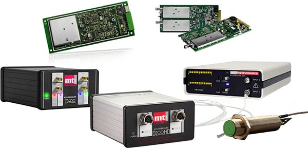
MTI charge amplifiers from Vitrek are designed specifically to address the challenges of precision vibration measurement. They play a key role in accelerometer signal conditioning by converting fragile charge signals into stable, low-impedance voltage outputs.
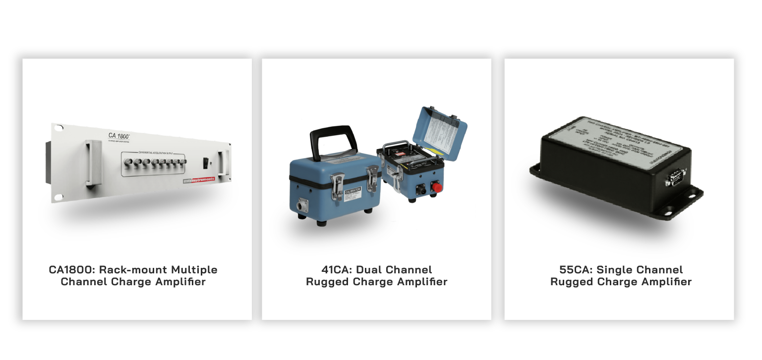
- 55CA: The 55CA provides single-channel signal conditioning in a portable package. It features switchable gains of 1, 4, and 10 mV/pC, allowing you to match sensor sensitivity and vibration amplitude to your data acquisition system’s input requirements. The unit handles long cable runs through ultra-high input impedance and low-noise amplification. Built-in filtering removes unwanted frequency content. The 55CA is well suited for field applications where portable, low-noise charge conditioning is required.
- 41CA: The 41CA offers dual-channel conditioning for balanced or differential sensor setups. Differential inputs reduce noise pickup by rejecting signals common to both channels. This is particularly important in electrically noisy environments or when measuring across structures with different ground potentials. The 41CA provides the same gain flexibility as the 55CA with synchronized dual-channel processing.
- CA1800: The CA1800 delivers multi-channel rack-mount amplification for laboratories and production environments. It accommodates multiple sensors simultaneously, maintaining consistent calibration across all channels. The rack-mount format integrates with standard test equipment configurations.
Engineering advantages common to MTI charge amplifiers include:
- Temperature-stable design for reliable operation across environmental conditions.
- The differential input and output configurations reduce noise pickup from electromagnetic sources.
- Optionally integrated velocity output eliminates the need for post-processing when balancing systems require velocity data.
Integration of MTI Charge Amplifiers with Measurement Systems
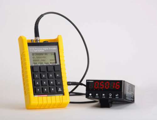
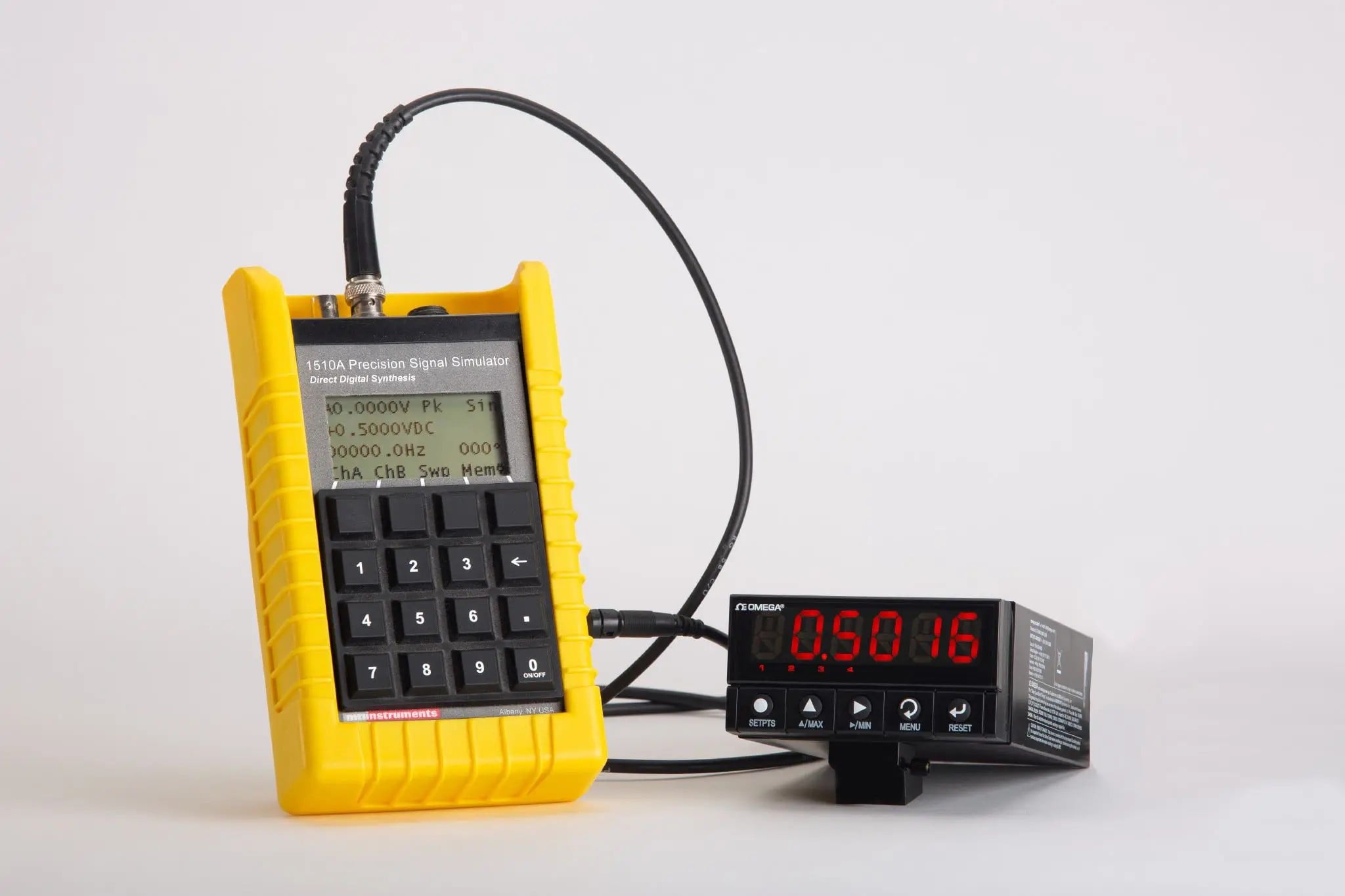
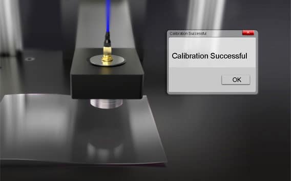
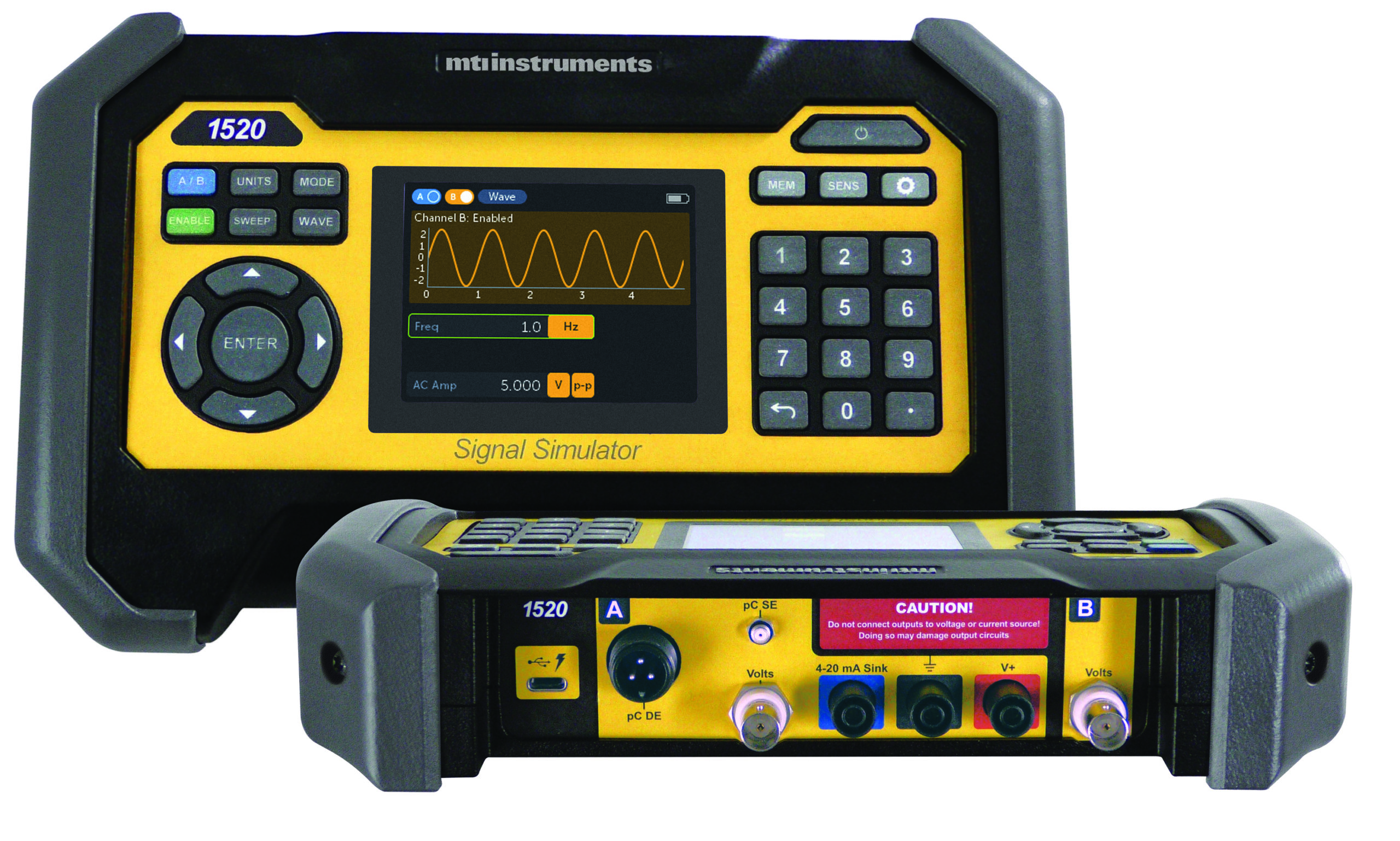
Integration of MTI charge amplifiers with data acquisition systems is straightforward. The low-impedance voltage output drives long cable runs to DAQ hardware without degradation. Compatibility with the MTI 1510A Signal Simulator enables calibration verification before testing begins. Apply a known signal at the amplifier input and confirm the expected output at your analyzer. This catches configuration errors, cable problems, or drift before you invest time in actual measurements.
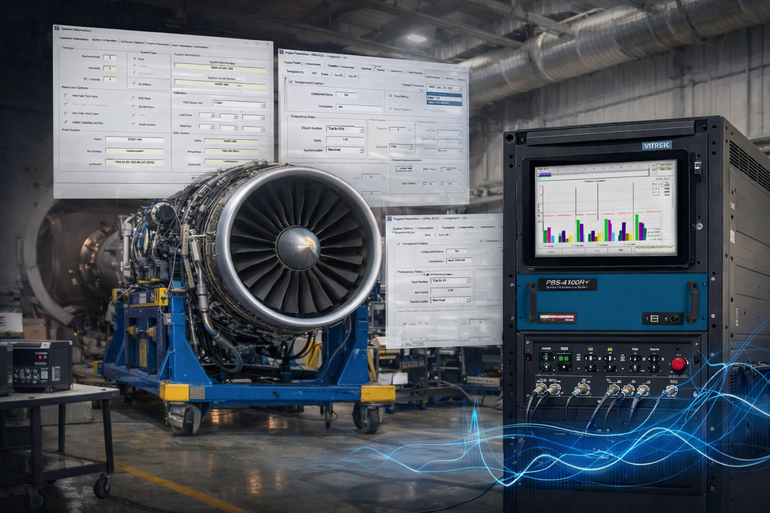
Example: Signal Flow in a Vibration Measurement System
A complete vibration measurement system links several components in sequence, with each stage playing a critical role in preserving signal integrity and measurement accuracy. This signal flow illustrates how accelerometer signal conditioning stabilizes the measurement chain before digitization and analysis.
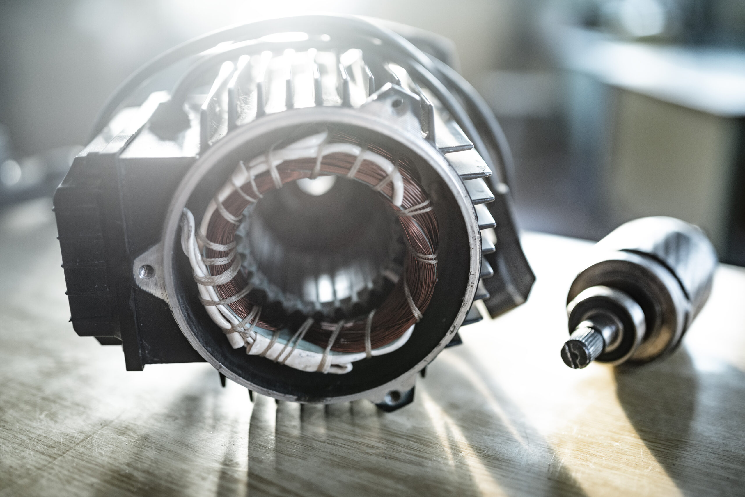
- The piezoelectric accelerometer mounts on the test article, such as bearing housing, turbine casing, or structural point of interest, where mechanical vibration generates charge output from the sensor.
- The charge signal travels through shielded cable to the MTI charge amplifier, where charge-to-voltage conversion occurs. The amplifier also provides impedance transformation, gain adjustment, and filtering to stabilize the signal.
- The conditioned voltage signal connects to your data acquisition system or analyzer. As the signal is now low impedance, it travels through cable runs without the degradation and noise susceptibility associated with unconditioned charge signals.
- Analysis software processes the digitized data using FFT analysis, order tracking, or other techniques to extract diagnostic information from the time-domain waveform.
Together, these stages ensure accurate amplitude, phase fidelity, and repeatable vibration measurements across a wide range of operating conditions.

Performance Outcomes
Proper accelerometer signal conditioning delivers measurable performance improvements.
- Proper signal conditioning can improve signal-to-noise ratio by tens of decibels compared to poorly conditioned systems, depending on sensor type, cabling, and environmental conditions.
- Amplitude and phase response remain stable across temperature changes and cable movement.
- Calibration traceability can be maintained because the charge amplifier’s transfer function is known and verified.
Emerging Trends in Signal Conditioning
Signal conditioning technology continues to evolve in response to increasing accuracy, reliability, and environmental demands in aerospace, power generation, and manufacturing.
- Hybrid conditioning architectures now combine charge and ICP inputs in single units. This allows mixed sensor types within one system, simplifying inventory and providing flexibility when sensor selection depends on local temperature or mounting constraints.
- Smart amplifiers with digital output interface directly to Ethernet, USB, or industrial protocols. They reduce reliance on long analog signal paths, lowering noise susceptibility and simplify system architecture in certain applications. Digital outputs also enable remote monitoring in distributed measurement networks.
- Remote, networked conditioning modules place signal conditioning near the sensors, even in locations separated from the control room. This minimizes analog cable runs where noise pickup occurs. The conditioned digital signals transmit over standard network infrastructure.
- Temperature-stable, low-noise designs continue improving. Aerospace and power generation applications demand reliable measurements in extreme environments. Charge amplifiers now operate reliably at higher ambient temperatures while maintaining low drift and noise specifications.
Accurate vibration and dynamic measurements depend on proper accelerometer signal conditioning. By transforming fragile, high-impedance charge signals into stable voltage outputs, charge amplifiers preserve signal integrity and measurement fidelity. At its core, accelerometer signal conditioning bridges the gap between raw sensor output and actionable vibration data.
When correctly implemented, charge amplification eliminates cable-related errors, minimizes drift, and enables precise analysis across a wide range of operating conditions. MTI charge amplifiers provide the performance, flexibility, and reliability required for modern vibration measurement systems in both field and laboratory environments.
Build Reliable Vibration Measurement Systems with MTI Charge Amplifiers
Incorporate MTI charge amplifiers into your measurement chain to preserve signal integrity, maintain phase accuracy, and ensure repeatable results across demanding vibration and dynamic test applications. Refer to the MTI Charge Amplifier product pages for configuration options and system integration details.


