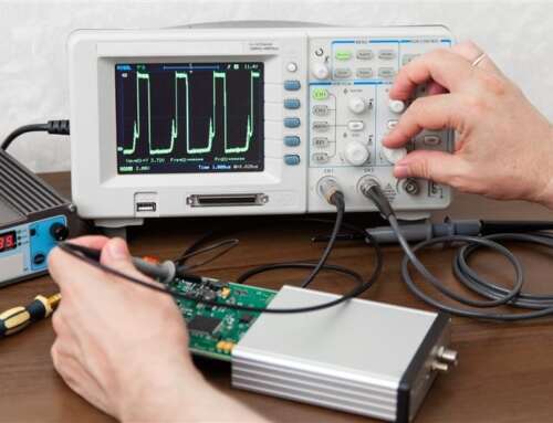
A harmonic plot that looks clean on screen can still be wrong by several percentage points if the setup is off. In regulated test environments, power analyzer setup for harmonics is not a clerical step. It determines whether the data is usable for design validation, troubleshooting, or compliance work.
Harmonic measurements are especially sensitive because small setup errors can distort both amplitude and phase relationships across the spectrum. A current probe with the wrong bandwidth, a voltage channel referenced incorrectly, or a sampling window that does not track line frequency can all shift the result. The analyzer may still produce a stable reading, but stability is not the same as accuracy.
What a correct power analyzer setup for harmonics must accomplish
A proper setup has to do more than capture volts and amps. It must preserve waveform fidelity, maintain timing alignment between channels, and apply harmonic analysis over a measurement interval that is consistent with the test objective. That sounds straightforward, but the right configuration depends on whether you are evaluating a variable-frequency drive, a switch-mode power supply, an inverter-fed motor, or a utility-connected load.
For low-order harmonic studies tied to power quality or standards-based testing, the priority is usually synchronized acquisition, stable frequency tracking, and repeatable FFT or harmonic grouping parameters. For higher-order content in switching systems, analog bandwidth, sensor response, and alias rejection become more important. The trade-off is that broader bandwidth can expose more noise, while heavier filtering can hide real distortion.
Start with the measurement objective
Before touching the analyzer menu, define what you need to report. If the goal is total harmonic distortion on a 60 Hz single-phase product, your setup can be optimized differently than if you are characterizing harmonic current up to the 50th order on a three-phase industrial drive. The test objective determines channel count, sensor selection, averaging behavior, and whether you need order-based harmonic analysis or broader spectral content.
This matters because not every harmonic setup should be configured for maximum bandwidth and maximum resolution. In many cases, that approach produces more unstable data, not better data. The correct setup is the one aligned to the waveform, frequency behavior, and reporting requirement.
Wiring and channel assignment
The first practical step is accurate voltage and current channel mapping. For single-phase measurements, that usually means confirming voltage reference polarity and placing the current sensor so positive power flow is interpreted correctly. For three-phase systems, phase rotation and wiring topology must match the analyzer configuration exactly, whether the unit under test is delta, wye, 3-wire, or 4-wire.
A mismatch here creates errors that extend beyond real power. Harmonic phase angles, sequence components, and derived distortion metrics can all be affected. Engineers sometimes focus on the FFT display and overlook the simpler check – verify that the fundamental voltage and current values, power factor, and total power direction are all physically reasonable before trusting the harmonic table.
Current sensor placement deserves special attention. Rogowski coils, shunts, Hall-effect sensors, and current transformers each introduce different bandwidth limits, phase shifts, and scaling concerns. A shunt may provide excellent linearity and harmonic fidelity, but it is not always practical at higher current or where isolation is required. A clamp-style sensor may be easier to deploy, but if its phase error rises with frequency, harmonic accuracy will suffer.
Sensor bandwidth and phase performance
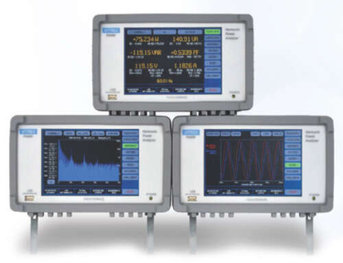
For harmonic work, bandwidth alone is not enough. The analyzer and the transducer need acceptable phase accuracy over the harmonic range of interest. If you are evaluating up to the 40th or 50th harmonic, sensor response that is adequate at the fundamental may still be inadequate higher up. This is one reason engineering-grade analyzers are preferred over generic power meters when compliance or design decisions depend on the result.
Set ranges for signal integrity, not convenience
Auto-ranging is useful during initial setup, but it is not always the best mode for final harmonic measurement. Range changes can interrupt continuity, alter resolution, or create uncertainty during dynamic conditions. Once the expected operating envelope is known, fixed ranges often provide better repeatability.
The objective is to maximize use of the analyzer’s input resolution without overdriving the channel. If the voltage channel is set far above the actual signal level, low-order harmonics may still read well, but smaller components can be buried in noise. If the range is too tight, clipping produces a harmonic spectrum that is obviously invalid. Either condition compromises the measurement.
The same logic applies to current. Inrush, startup events, and pulsed loading may require more headroom than steady-state current suggests. It depends on whether you are measuring a stable operating point or observing a transient operating sequence.
Synchronization, sampling, and line frequency tracking
One of the most common sources of bad harmonic data is a measurement window that is not synchronized to the waveform. Harmonic analysis assumes a stable relationship between the sampling interval and the fundamental frequency. If the analyzer is not tracking line frequency correctly, spectral leakage increases and harmonic magnitudes can shift.
For fixed-frequency mains testing, this is usually manageable if the analyzer has solid phase-locked acquisition. For variable-frequency sources, motor drives, or inverter outputs, it becomes more complicated. Some analyzers handle this well with advanced synchronization modes, while others require careful manual configuration. The correct approach depends on whether the signal is quasi-periodic, frequency-agile, or heavily modulated.
Sampling rate also matters. Too low, and higher-order components fold back or disappear. Excessively high, and file size and processing time increase without adding useful information for a standards-limited harmonic report. In practice, sampling should be set high enough to cover the harmonic order of interest with margin for anti-alias filtering and waveform integrity.
Window length and averaging
Longer averaging intervals can stabilize readings, especially on noisy loads, but they can also hide operating variability. If the unit under test changes mode every few seconds, a long average may understate actual distortion peaks. A short window gives better visibility into behavior changes but may look less repeatable.
That is not a flaw in the analyzer. It reflects the source behavior. The setup should match the purpose of the test – troubleshooting, product characterization, or pass-fail evaluation.
FFT and harmonic analysis settings
The analyzer’s harmonic function is only as useful as its configuration. Engineers should confirm the fundamental frequency reference, harmonic order limit, grouping method, and whether interharmonics are included or excluded. These settings can change the reported values materially, especially when switching edges or nonstationary waveforms are present.
If you need data aligned to a specific compliance framework, configure the analyzer to match that framework rather than using a generic spectrum mode. Harmonic subgrouping, smoothing, and reporting intervals are not interchangeable across all applications. This is where application-specific instrumentation support can save time, because the wrong default setting may still look technically plausible.
Filtering requires judgment. Input filters can improve readability by suppressing out-of-band noise, but they can also suppress legitimate high-frequency content that influences distortion metrics. For that reason, any enabled filter should be intentional and documented.
Grounding, shielding, and noise control
Harmonic measurement is often performed around switching converters, drives, and high-current conductors, which means electromagnetic noise is part of the environment. Poor lead routing, floating references, or inadequate shielding can inject artifacts that appear as harmonic content.
Keep voltage leads short where practical, separate signal wiring from high-current switching paths, and avoid ground loops between the analyzer, source, and unit under test. Differential inputs help, but they do not eliminate bad wiring practices. If the harmonic spectrum changes significantly when cables are moved, you may be measuring the setup as much as the device.
Verification before you trust the data
Before recording formal results, perform a quick validation. Compare the analyzer’s RMS and power readings against expected operating values. Review the waveform shape in the time domain. Check whether harmonic amplitudes change logically with load, speed, or switching condition. If the fifth and seventh harmonics jump unpredictably while the waveform appears stable, the issue may be setup-related rather than product-related.
A known reference load or a previously characterized source is useful here. In higher-confidence labs, traceable calibration status and documented setup parameters are part of the measurement integrity, not just paperwork. That is particularly relevant in aerospace, medical, automotive, and defense programs where the test record may need to support qualification or audit activity.
When setup errors look like product problems
A recurring issue in harmonic troubleshooting is assigning a waveform anomaly to the device under test when the real cause is the measurement chain. Saturated current sensors can exaggerate distortion. Unsynchronized capture can smear low-order components. Incorrect phase assignment in a three-phase system can make one phase appear noncompliant when the setup is the actual fault.
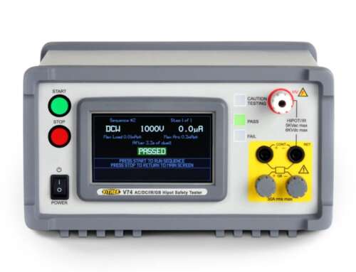
That is why engineering teams should treat power analyzer setup for harmonics as part of the test method. It is not separate from the result. On advanced systems, instruments from manufacturers such as Vitrek are designed to support this level of repeatability, but the instrument alone does not guarantee good data. Configuration discipline still matters.
The practical test is simple: if another qualified engineer cannot reproduce your harmonic result from your documented setup, the measurement process needs tightening. Good harmonic data starts long before the report is generated, and careful setup is usually the difference between a useful diagnosis and a very expensive assumption.


