An EV inverter can post excellent efficiency on paper and still fail validation if the measurement chain is not built for PWM-rich, fast-changing power. That is why an ev inverter power measurement guide has to start with the instrument itself, not the datasheet headline number. In traction inverter testing, small timing errors, poor sensor selection, or incomplete bandwidth can distort switching loss, efficiency, and harmonic results enough to send engineering teams in the wrong direction.
What makes EV inverter power measurement difficult
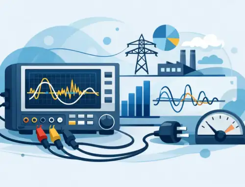
Unlike line-frequency power testing, inverter measurement sits in a mixed world of high DC bus voltage, fast edge rates, non-sinusoidal waveforms, and dynamic operating points. You are rarely measuring a calm, steady load. You are measuring a system that is switching aggressively while responding to torque commands, speed changes, and thermal constraints.
The first challenge is waveform complexity. Voltage and current are not simple sine waves, and the relationship between them changes within each switching cycle. If voltage and current channels are not synchronized precisely, computed power can shift enough to mask real losses or create losses that do not exist.
The second challenge is common-mode voltage and electrical noise. Wide bandgap devices such as SiC push switching speeds higher, which can improve efficiency but also stress probes, transducers, and analyzer front ends. In these setups, measurement quality depends as much on immunity and isolation as on nominal accuracy.
The third challenge is that the answer depends on where you measure. DC input power, three-phase AC output power, motor-side mechanical output, and battery emulation conditions all reveal different aspects of inverter performance. A valid result starts with a clear definition of what power path is under test.
EV inverter power measurement guide: start with the test objective
Before selecting instruments, define the exact question the test must answer. Development engineers may care about switching loss by operating point, while production teams may need repeatable pass-fail efficiency checks. Compliance groups may be focused on traceable measurements that can stand up during audit or customer review.
That objective determines the required bandwidth, sample rate, uncertainty, and automation level. For example, if the goal is average efficiency across a drive cycle, a high-accuracy power analyzer with stable integration and synchronized multi-channel capture is usually central. If the goal is to separate conduction and switching losses in a SiC inverter leg, you may also need high-speed digitizers, differential voltage measurements with strong common-mode rejection, and current sensing that preserves fast transient content.
It is easy to overbuild the setup. It is just as easy to underbuild it. The right architecture depends on whether you need certification-grade numbers, design-debug visibility, or production throughput.
Measuring the right signals, at the right locations
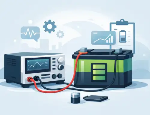
Most EV inverter tests begin with DC bus voltage and current at the inverter input, then add three-phase output voltage and current at the motor side. That gives you a practical basis for DC-to-AC conversion efficiency. In many labs, this is enough for top-level characterization.
However, if you are investigating device behavior, modulation strategy, or thermal anomalies, that basic view may not be sufficient. Gate signals, phase-to-phase voltages, phase currents, torque, speed, and temperature often need to be correlated. Once those signals come into scope, channel synchronization becomes critical. A collection of accurate instruments is not the same thing as an accurate system if timestamps drift or trigger relationships are ambiguous.
Sensor placement also matters more than many teams expect. Cable inductance, grounding choices, and probe lead length can influence what the instrument sees, especially near switching transitions. A probe that performs well on a bench converter may become the limiting factor in a full-power traction setup.
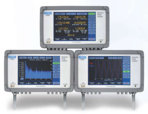
Instrument selection: accuracy is only one part of the answer
A credible ev inverter power measurement guide should treat accuracy, bandwidth, and isolation as a package. A power analyzer with excellent basic accuracy but limited bandwidth may be ideal for averaged efficiency testing and less useful for detailed switching analysis. A high-speed digitizer can expose transient behavior, but without careful scaling, calibration, and math methods, it may not deliver the uncertainty needed for final reporting.
For DC input measurement, precision shunts, Hall sensors, or zero-flux transducers each have trade-offs. Shunts can offer strong linearity and traceability but introduce insertion loss and thermal considerations. Hall devices are convenient and isolated, though offset and bandwidth may limit some applications. Zero-flux transducers are often preferred where accuracy and dynamic response both matter, but they add cost and setup complexity.
Voltage measurement carries similar trade-offs. Differential high-voltage probes must withstand the common-mode environment without excessive phase error. In inverter work, phase accuracy is not a secondary specification. Real power calculations depend on it.
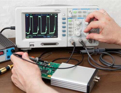
This is where engineering-grade analyzers and acquisition systems matter. In practice, teams often need both a precision power analyzer for trusted power numbers and a high-speed capture platform for root-cause analysis. Used together, they can separate reporting-grade results from waveform investigation instead of asking one tool to do both jobs poorly.
Timing, synchronization, and computed power
Real power is a time-domain calculation. That sounds obvious, but it is the source of many bad measurements. If voltage and current are sampled on different clocks, processed with mismatched delays, or passed through sensors with different phase shifts, the error shows up directly in power.
This becomes more severe at high switching frequencies and under light-load conditions, where the difference between input and output power may be relatively small. If your setup introduces even modest phase error, the calculated loss can move by a meaningful amount.
The practical fix is disciplined synchronization. Use instruments designed for simultaneous sampling or verified timing alignment. Characterize sensor delay. Confirm channel matching under known conditions before trusting efficiency data. If software is applying scaling or resampling after acquisition, validate that process too. Post-processing can improve usability, but it cannot restore information that the front end failed to capture correctly.
Bandwidth and filtering: enough to measure, not enough to distort
There is no universal bandwidth setting for inverter power measurement. Too little bandwidth and you smooth away switching content that contributes to loss. Too much bandwidth and noise may dominate, especially in electrically harsh environments. The correct setting depends on the measurement purpose.
For average efficiency, controlled filtering can improve repeatability if it is applied consistently and documented. For switching analysis, aggressive filtering can hide the very behavior you are trying to quantify. Engineers should decide whether the reported number is intended to represent fundamental power, total power including high-frequency content, or a standards-defined quantity tied to a specific method.
This is also where test reports often become hard to compare across teams or suppliers. Two labs may both report inverter efficiency, yet use different bandwidth limits, averaging windows, and sensor classes. The difference is not always in the inverter. Sometimes it is in the method.
Uncertainty, calibration, and traceability
In regulated and performance-critical environments, a measured value without uncertainty context is incomplete. That does not mean every lab report needs a lengthy metrology appendix, but it does mean the test team should understand the dominant error sources. Sensor accuracy, analyzer accuracy, temperature drift, phase shift, scaling factors, and wiring effects all contribute.
Calibration traceability is equally important. EV programs often move from R&D benches to validation labs to manufacturing screens, and data credibility depends on a consistent measurement framework. If one station uses recently calibrated instruments and another relies on undocumented correction factors, trend analysis becomes questionable.
For organizations building formal test infrastructure, this is where a supplier with a strong metrology and support background can make a measurable difference. Vitrek, for example, serves teams that need not only high-performance instruments but also repeatable, standards-aware measurement workflows.
Common setup mistakes that distort results
The most common problem is treating the inverter like a conventional AC source. It is not. Standard utility-power assumptions break down quickly in PWM environments.
Another mistake is focusing on current range and ignoring voltage probe performance. In many failed setups, current measurement is acceptable while voltage phase fidelity is not. The result is clean-looking but inaccurate power data.
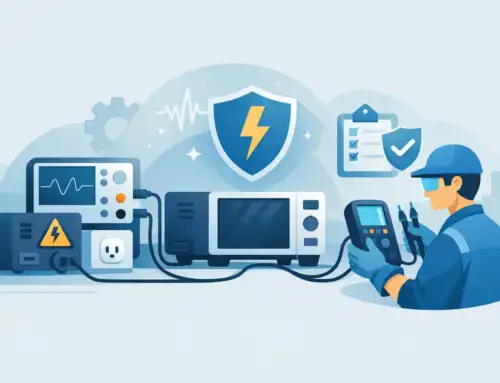
A third issue is insufficient attention to grounding and wiring layout. High dv/dt systems punish casual test wiring. Noise pickup, ground loops, and unexpected common-mode behavior can shift both stability and accuracy. If the measured waveform changes materially when probe routing changes, the setup still needs work.
Building a measurement approach that scales
For early-stage development, flexibility matters. Teams need to reconfigure channels, inspect transient behavior, and compare control strategies quickly. For validation and production, repeatability matters more. The test architecture should reflect that difference.
A scalable approach usually starts with a validated core method for input and output power, then adds synchronized channels for mechanical and thermal variables as needed. Document the sensor types, calibration state, bandwidth limits, averaging windows, and computation method. That level of discipline reduces retest cycles and makes cross-site comparisons more credible.
The best measurement setup is not the one with the longest specification sheet. It is the one that answers the engineering question with known uncertainty, repeatable execution, and enough headroom for the next inverter generation. As switching speeds rise and efficiency margins tighten, measurement quality stops being a support function and becomes part of the design process itself.


