Vitrek White Papers
 Whitepaper: The Future of Cable Testing: Why Intelligent Automation is Replacing Manual Validation Gallery
Whitepaper: The Future of Cable Testing: Why Intelligent Automation is Replacing Manual Validation
Brand-Vitrek, Industry-Aerospace, Industry-Automotive, Industry-Cable Test, Industry-Compliance Testing, Industry-Consumer Products, Industry-Electronics, Industry-Government/Military, Industry-Lighting, Industry-Manufacturing, Industry-Medical, New & Press Releases, Whitepapers-Vitrek
 Automating Complex Cable Testing with the Vitrek V10X and 964i Gallery
Automating Complex Cable Testing with the Vitrek V10X and 964i
Application Notes-Vitrek, Brand-Vitrek, Industry-Aerospace, Industry-Automotive, Industry-Cable Test, Industry-Compliance Testing, Industry-Consumer Products, Industry-Electronics, Industry-Government/Military, Industry-Lighting, Industry-Manufacturing, Industry-Medical, Whitepapers-Vitrek


 Application Note: Replace Three Legacy Systems with One: Modernizing Aerospace/Defense Test Cells with PBS eXpress Gallery
Application Note: Replace Three Legacy Systems with One: Modernizing Aerospace/Defense Test Cells with PBS eXpress
Application Notes-MTI, Brand-MTI, Industry-Aerospace, New & Press Releases, News-Industry, News-MTI, Whitepapers-MTI
 Application Note: Accessing Digital Engine Data for Multi-Platform Aircraft Balancing with MTI PBS Systems Gallery
Application Note: Accessing Digital Engine Data for Multi-Platform Aircraft Balancing with MTI PBS Systems
Application Notes-MTI, Brand-MTI, Industry-Aerospace, New & Press Releases, News-Industry, News-MTI, Whitepapers-MTI
 Choosing the Right Hipot Platform for Modern Manufacturing Electrical Safety Testing Gallery
Choosing the Right Hipot Platform for Modern Manufacturing Electrical Safety Testing
Articles-Vitrek, Industry-Automotive, Industry-Battery, Industry-Cable Test, Industry-Compliance Testing, Industry-Consumer Products, Industry-Electronics, Industry-Government/Military, Industry-Lighting, Industry-Manufacturing, Industry-Medical, Industry-R&D, Knowledge Center-Vitrek, New & Press Releases, Whitepapers-Vitrek

 Enabling Intelligent, Automation-Ready Electrical Safety Testing in Modern Production Gallery
Enabling Intelligent, Automation-Ready Electrical Safety Testing in Modern Production
Application Notes-Vitrek, Brand-Vitrek, Industry-Compliance Testing, Industry-Electronics, Industry-Manufacturing, Industry-Measurement Applications, Whitepapers-Vitrek

 Testing Energy-Efficient Washing Machines with the PA900 Power Analyzer Gallery
Testing Energy-Efficient Washing Machines with the PA900 Power Analyzer
Application Notes-Vitrek, Brand-Vitrek, Industry-Compliance Testing, Industry-Electronics, Industry-Manufacturing, Industry-Measurement Applications, Whitepapers-Vitrek
 Ultra-Low Standby Power Testing Made Simple with Vitrek Power Analyzers and EN50564:2011 Gallery
Ultra-Low Standby Power Testing Made Simple with Vitrek Power Analyzers and EN50564:2011
Application Notes-Vitrek, Brand-Vitrek, Industry-Compliance Testing, Industry-Electronics, Industry-Manufacturing, Industry-Measurement Applications, Whitepapers-Vitrek
 Power Analyzers: The Backbone of Modern Electrical Engineering Gallery
Power Analyzers: The Backbone of Modern Electrical Engineering
Brand-Vitrek, Industry-Automotive, Industry-Compliance Testing, Industry-Consumer Products, Industry-Energy, Industry-Manufacturing, Industry-Medical, Industry-Medical, Industry-OEM, Industry-R&D, Industry-Semiconductor, News-All Brands, Products-Vitrek-Power-Analyzer, Whitepapers-Vitrek

 Application Note: Maximizing High-Voltage Measurement Accuracy with the Vitrek 4700 Gallery
Application Note: Maximizing High-Voltage Measurement Accuracy with the Vitrek 4700
Brand-Vitrek, Industry-Cable Test, Industry-Compliance Testing, Industry-Manufacturing, Products-Vitrek-4700, Whitepapers-Vitrek, z1


 Whitepaper: Mastering High Voltage: The Importance of Accurate Test Equipment Gallery
Whitepaper: Mastering High Voltage: The Importance of Accurate Test Equipment
Industry-Cable Test, Industry-Compliance Testing, Industry-Consumer Products, Industry-Electronics, Industry-Manufacturing, Industry-Measurement Applications, Knowledge Center-Vitrek, News-Vitrek, Whitepapers-Vitrek

 Did You Know? GaGe RazorMax Express Digitizer/Oscilloscope: An Efficient & Cost-Effective Tool for High-Energy Physics Particle Counting Applications Gallery
Did You Know? GaGe RazorMax Express Digitizer/Oscilloscope: An Efficient & Cost-Effective Tool for High-Energy Physics Particle Counting Applications
Brand-GaGe, Industry-Government/Military, Industry-Measurement Applications, Industry-Medical, Industry-R&D, Industry-Semiconductor, Industry-Semiconductor-GaGe, Knowledge Center-GaGe, Whitepapers-GaGe

 Case-In-Point: MTI Turbine Vibration Analyzer/Balancing System Technology Principles Gallery
Case-In-Point: MTI Turbine Vibration Analyzer/Balancing System Technology Principles
Application Notes-MTI, Articles-MTI, Industry-Aerospace, Industry-Compliance Testing, Industry-Government/Military, Industry: Transportation, Knowledge Center-MTI, News-Industry, News-MTI-PBS, Whitepapers-MTI
 Article: High-Performance Digitizers in Semiconductor Manufacturing Applications Gallery
Article: High-Performance Digitizers in Semiconductor Manufacturing Applications
Application Notes-GaGe, Articles-GaGe, Industry-Compliance Testing, Industry-Semiconductor, Industry-Semiconductor-GaGe, Knowledge Center-GaGe, News-GaGe, News-Industry, Whitepapers-GaGe
 MTI Instruments Whitepaper: Capacitance Guide for Industrial Applications Gallery
MTI Instruments Whitepaper: Capacitance Guide for Industrial Applications
Brand-MTI, Industry-Aerospace, Industry-Automotive, Industry-Battery, Industry-Compliance Testing, Industry-Consumer Products, Industry-Electronics, Industry-Energy, Industry-Government/Military, Industry-Industrial Processing, Industry-Lighting, Industry-Manufacturing, Industry-Measurement Applications, Industry-OEM, Industry-R&D, Industry-Semiconductor, Industry-Semiconductor-MTI, Industry-Sensors, Industry: Transportation, Knowledge Center-MTI, News-MTI, Whitepapers-MTI


 Whitepaper: Why Capacitance? Benefits and Applications of Digital Capacitive Sensors Gallery
Whitepaper: Why Capacitance? Benefits and Applications of Digital Capacitive Sensors
Brand-MTI, Industry-Automotive, Industry-Compliance Testing, Industry-Consumer Products, Industry-Electronics, Industry-Industrial Processing, Industry-Manufacturing, Industry-Measurement Applications, Industry-Semiconductor, Industry-Semiconductor-MTI, Industry-Sensors, Knowledge Center-MTI, News-MTI, News-Vitrek, Whitepapers-MTI
 Whitepaper: Semiconductor Wafer Measurement for Increased Productivity Gallery
Whitepaper: Semiconductor Wafer Measurement for Increased Productivity
Brand-GaGe, Brand-MTI, Brand-Vitrek, Brands-All, Industry-Consumer Products, Industry-Electronics, Industry-Manufacturing, Industry-OEM, Industry-Semiconductor, Industry-Semiconductor-MTI, Knowledge Center-MTI, News-Industry, News-MTI, Whitepapers-MTI


 GaGe Whitepaper: Wide Bandwidth Digitizer Provides Essential Data Processing in an Innovative Real-Time Channel Sounder for 5G Applications Gallery
GaGe Whitepaper: Wide Bandwidth Digitizer Provides Essential Data Processing in an Innovative Real-Time Channel Sounder for 5G Applications
Industry-Aerospace, Industry-Consumer Products, Industry-Electronics, Industry-Government/Military, Whitepapers-GaGe, z1, ZOK


 MTI Whitepaper: Easy Roller Gap Measurement Ensures Calendering Success Gallery
MTI Whitepaper: Easy Roller Gap Measurement Ensures Calendering Success
Brand-MTI, Industry-Consumer Products, Industry-Manufacturing, Industry-Sensors, News-MTI-Instrumentation, Products-MTI-Capacitance, Whitepapers-MTI, z1
 A Comprehensive Guide to Non-Contact Sensors and Their Applications Gallery
A Comprehensive Guide to Non-Contact Sensors and Their Applications
Application Notes-MTI, Articles-MTI, Brand-MTI, Industry-Sensors, News-MTI-Metrology, Products-MTI-Capacitance, Products-MTI-Laser/Fiber Optic, Products-MTI-Semiconductor/Metrology, Whitepapers-MTI, Z-REPUB, z1
 Vitrek’s Automated Testing System Simplifies and Speeds Automotive Cable/Harness Testing Gallery
Vitrek’s Automated Testing System Simplifies and Speeds Automotive Cable/Harness Testing
Application Notes-Vitrek, Brand-Vitrek, Industry-Automotive, Industry-Consumer Products, Industry-Government/Military, Industry: Transportation, Whitepapers, z1
 White Paper: High Performance Test Equipment Assures LED Lighting Products Comply with Industry Standards Gallery
White Paper: High Performance Test Equipment Assures LED Lighting Products Comply with Industry Standards
Brand-Vitrek, Industry-Consumer Products, Industry-Lighting, News-Industry, News-Vitrek, Products-Vitrek, Whitepapers-Vitrek, z1
 Aircraft Vibration Analysis and Measurement Techniques Gallery
Aircraft Vibration Analysis and Measurement Techniques
Brand-MTI, Industry-Aerospace, Industry-Compliance Testing, Industry-Government/Military, Industry-Manufacturing, Industry: Transportation, Knowledge Center-MTI, News-MTI-PBS, Whitepapers-MTI, Z-REPUB, z1


 White Paper: Electrical Safety & Compliance Testing for Appliance & Consumer Product Manufacturers Gallery
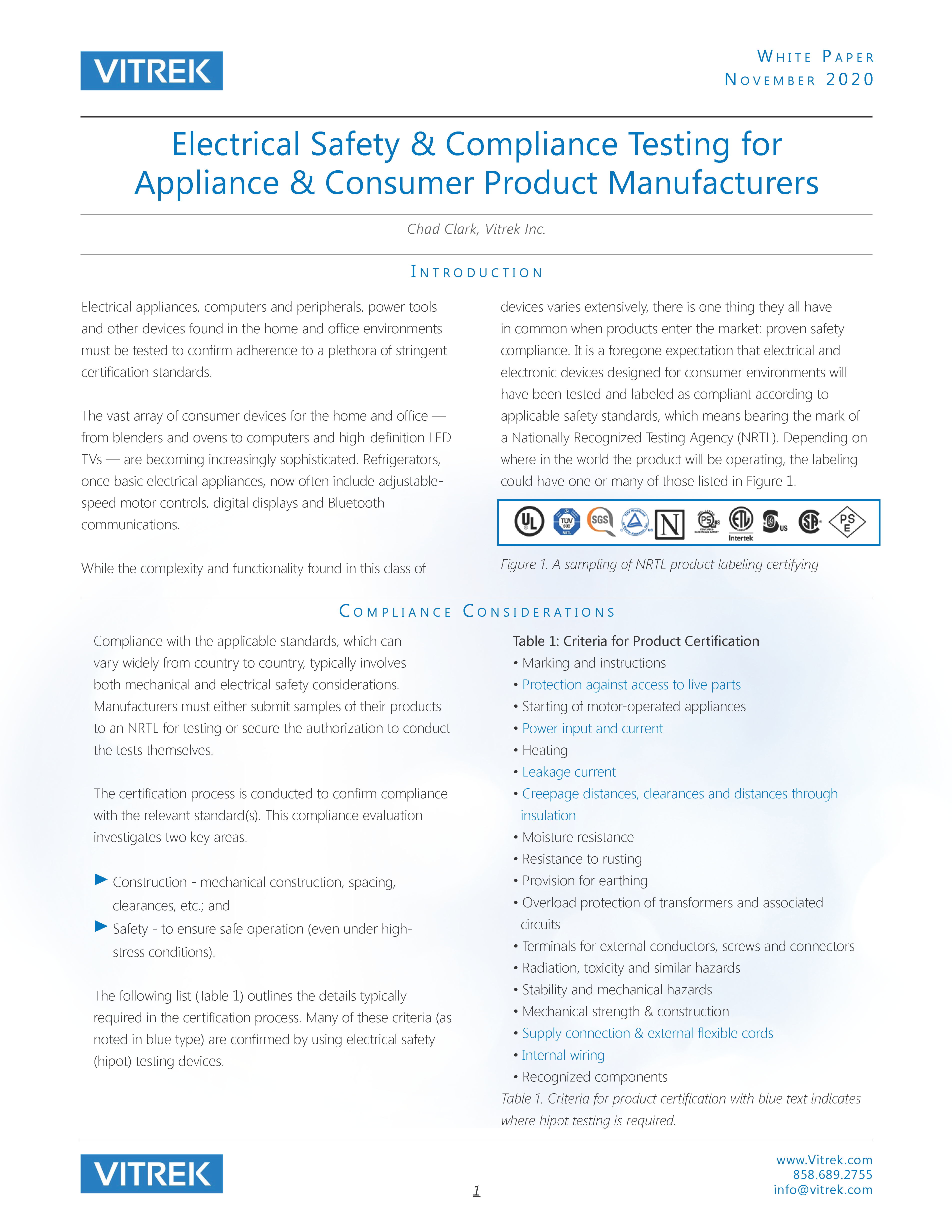
White Paper: Electrical Safety & Compliance Testing for Appliance & Consumer Product Manufacturers
Brand-Vitrek, Industry-Compliance Testing, Industry-Consumer Products, Industry-Electronics, Industry-Manufacturing, News-Vitrek, Products-Vitrek, Whitepapers-Vitrek, z1
 White Paper: Cable & Connector Test System Facilitates Multi-Point High Voltage/Current Testing Gallery
White Paper: Cable & Connector Test System Facilitates Multi-Point High Voltage/Current Testing
Brand-Vitrek, Industry-Aerospace, Industry-Automotive, Industry-Cable Test, Industry-Compliance Testing, Industry-Consumer Products, Industry-Government/Military, Industry-Manufacturing, Industry: Transportation, Whitepapers-Vitrek
 White Paper: Precision Power Analyzers Gallery
White Paper: Precision Power Analyzers
Brand-Vitrek, Industry-Compliance Testing, Industry-Consumer Products, Industry-Electronics, Industry-Energy, Industry-Manufacturing, Industry-R&D, News-Product Updates, News-Products, News-Vitrek, Products-Vitrek-Power-Analyzer, Whitepapers-Vitrek, z1
 Measuring Brake Rotor Thickness Variation with Capacitive Sensing Gallery
Measuring Brake Rotor Thickness Variation with Capacitive Sensing
Brand-MTI, Industry-Aerospace, Industry-Automotive, Industry-Consumer Products, Industry-Government/Military, Industry-Manufacturing, Industry: Transportation, Knowledge Center-MTI, Products-MTI-Capacitance, Whitepapers-MTI, Z-REPUB, z1


Articles
- Choosing the Right Hipot Platform for Modern Manufacturing Electrical Safety Testing Gallery
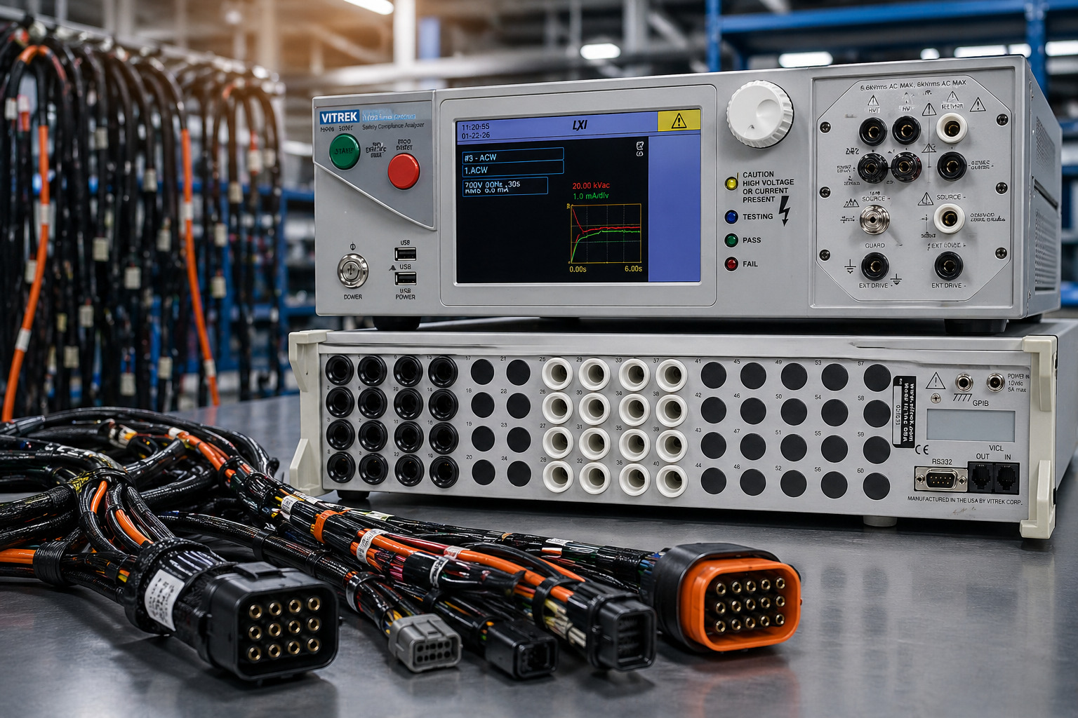
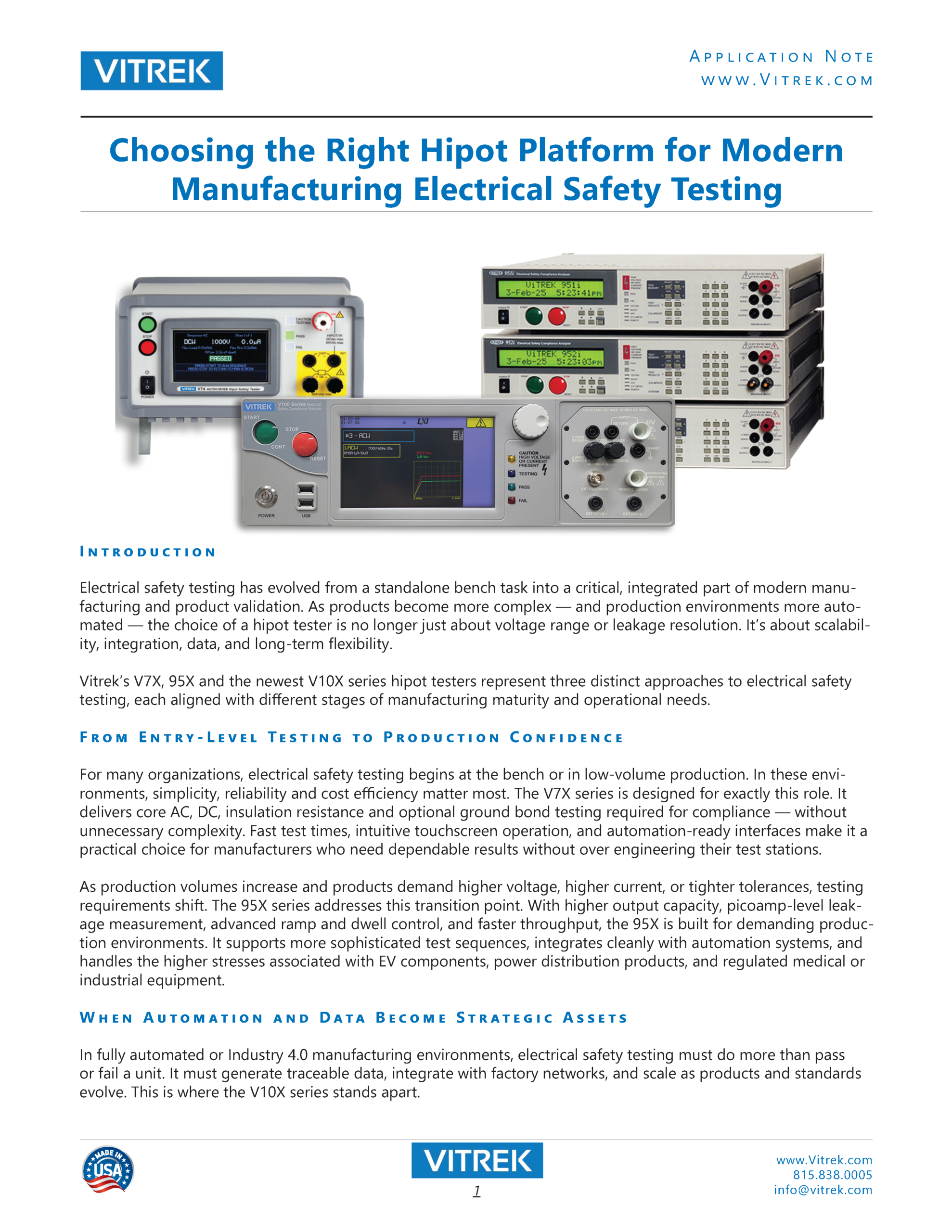
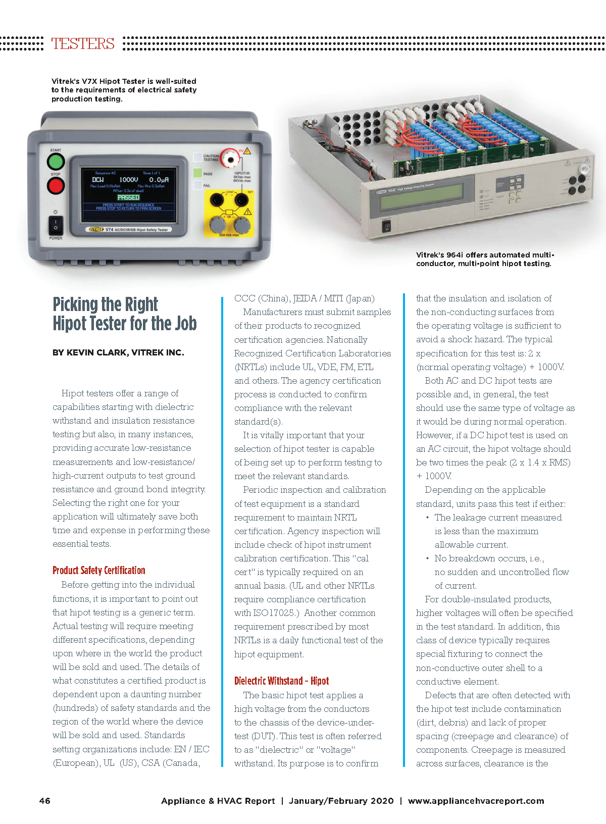
Choosing the Right Hipot Platform for Modern Manufacturing Electrical Safety Testing
Articles-Vitrek, Industry-Automotive, Industry-Battery, Industry-Cable Test, Industry-Compliance Testing, Industry-Consumer Products, Industry-Electronics, Industry-Government/Military, Industry-Lighting, Industry-Manufacturing, Industry-Medical, Industry-R&D, Knowledge Center-Vitrek, New & Press Releases, Whitepapers-Vitrek

- Case-In-Point: MTI Turbine Vibration Analyzer/Balancing System Technology Principles Gallery
Case-In-Point: MTI Turbine Vibration Analyzer/Balancing System Technology Principles
Application Notes-MTI, Articles-MTI, Industry-Aerospace, Industry-Compliance Testing, Industry-Government/Military, Industry: Transportation, Knowledge Center-MTI, News-Industry, News-MTI-PBS, Whitepapers-MTI
- Article: High-Performance Digitizers in Semiconductor Manufacturing Applications Gallery
Article: High-Performance Digitizers in Semiconductor Manufacturing Applications
Application Notes-GaGe, Articles-GaGe, Industry-Compliance Testing, Industry-Semiconductor, Industry-Semiconductor-GaGe, Knowledge Center-GaGe, News-GaGe, News-Industry, Whitepapers-GaGe
 Article: Advanced Test Equipment Enables LED Lighting Manufacturers to Ensure Compliance with Standards-August, 2022-Designing-Electronics.com Gallery
Article: Advanced Test Equipment Enables LED Lighting Manufacturers to Ensure Compliance with Standards-August, 2022-Designing-Electronics.com
Articles-Vitrek, Brand-Vitrek, Industry-Lighting, News-Vitrek, Products-Vitrek, Products-Vitrek-4700, Products-Vitrek-964i, Products-Vitrek-98x, Products-Vitrek-DL Load, Products-Vitrek-Hipot, Products-Vitrek-Power-Analyzer, Products-Vitrek-QT, z1
 Why You Need Automotive Cable Tests Before Cars Hit the Road Gallery
Why You Need Automotive Cable Tests Before Cars Hit the Road
Articles-Vitrek, Blog, Brand-Vitrek, Electrical Safety Testing Blog, Industry-Automotive, Industry-Cable Test, Industry-Compliance Testing, Industry-Government/Military, Industry-Manufacturing, Industry: Transportation, Products-Vitrek-964i, z1

- A Comprehensive Guide to Non-Contact Sensors and Their Applications Gallery
A Comprehensive Guide to Non-Contact Sensors and Their Applications
Application Notes-MTI, Articles-MTI, Brand-MTI, Industry-Sensors, News-MTI-Metrology, Products-MTI-Capacitance, Products-MTI-Laser/Fiber Optic, Products-MTI-Semiconductor/Metrology, Whitepapers-MTI, Z-REPUB, z1


 How Aircraft Operators Reduce Downtime While “Sweating the Assets” Gallery
How Aircraft Operators Reduce Downtime While “Sweating the Assets”
Articles-MTI, Brand-MTI, Industry-Aerospace, Industry-Compliance Testing, Industry-Government/Military, Industry-Manufacturing, Industry: Transportation, News-MTI-PBS, Products-MTI-Engine Balancing, Z-REPUB, z1


Vitrek in the News…
What Is Leakage Current Testing?
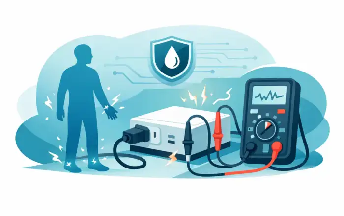
A product can pass functional test, insulation resistance, and even hipot, then still fail in the field for one simple reason – too much unintended current reaches a user-accessible surface or patient connection. That is why engineers ask what is leakage current testing, not as a theoretical question, but as a practical one tied to safety, compliance, and product release.
Leakage current testing is the process of measuring small amounts of unintended current that flow from energized parts of an electrical device to ground, chassis, enclosure surfaces, or applied parts. The purpose is to confirm that the product stays within allowable limits defined by the applicable safety standard under normal operation and, in many cases, under single-fault conditions. In regulated environments, that distinction matters. A device does not need a catastrophic insulation breakdown to create a safety issue. Milliamps or even microamps in the wrong path can be enough to fail compliance or create risk.
The concept sounds straightforward, but the details vary by product category, installation class, and standard. A consumer appliance, a laboratory instrument, and a medical device may all require leakage current testing, yet the measurement methods, load networks, pass limits, and fault simulations can be very different.
What is leakage current testing measuring?
At its core, leakage current testing measures current that was not intended to be part of the device’s normal functional output. Some leakage is expected in real electrical systems. EMI suppression components, parasitic capacitance, power supply design, and insulation structures all create small current paths. The engineering question is not whether leakage exists. It is whether the leakage remains below the level permitted for the product’s intended use.
Several measurement categories are common. Ground leakage current evaluates current flowing from the equipment to protective earth. Touch current, sometimes called enclosure leakage in certain contexts, measures current that could flow through a person touching accessible conductive parts. In medical equipment, patient leakage current and patient auxiliary current receive even tighter attention because the current path may involve direct or indirect patient contact.
This is where test intent matters. A leakage measurement is not simply a low-current check performed with a generic meter. It is typically conducted through a defined measuring network that models human body impedance or another standard-prescribed load. The tester, switching arrangement, and measurement circuit all need to align with the governing requirement.
Why leakage current matters in product safety
Leakage current is one of those parameters that sits at the intersection of design, compliance, and real-world use. From a design standpoint, it reflects insulation strategy, filtering choices, transformer construction, shielding, wiring layout, and grounding architecture. From a compliance standpoint, it is a documented electrical safety requirement. From a field perspective, it can influence user perception, nuisance trips, and actual hazard exposure.
Consider a line-powered product with aggressive EMI filtering. Increasing filter capacitance may improve emissions performance, but it can also increase leakage to ground. That trade-off is common in industrial and medical design. The product team may need to balance electromagnetic compatibility targets against touch current or earth leakage limits. There is no universal best value. It depends on the product class, installation environment, and standard.
Leakage current testing also helps expose issues that a simple continuity check will miss. A chassis may be solidly bonded to protective earth and still exhibit unacceptable current because of internal capacitive coupling or component degradation. In production, leakage measurements can reveal assembly variation, damaged insulation, incorrect wiring, or substitution of nonqualified parts.
How leakage current testing is performed
In most cases, leakage current testing is performed with the device energized in a defined operating state. The equipment under test is connected according to the applicable standard, and the test instrument measures current through a specified network while the product operates under normal and sometimes fault conditions.
The exact setup depends on what is being measured. For touch current, the tester may connect the measuring network between accessible conductive parts and earth. For earth leakage, the current in the protective ground path is measured. For medical devices, the setup can become more complex, with measurements taken from enclosure, earth, and patient connections under multiple switch positions and fault simulations.
Supply polarity, line voltage, frequency, and grounding configuration can all affect the result. So can the operational mode of the device. A system may show one leakage value at idle and another under full load, charging, heating, or RF transmission. That is why leakage current testing should reflect realistic worst-case operating conditions rather than a convenient bench state.
Single-fault testing is often part of the requirement. Engineers may open the protective earth, reverse line polarity, disconnect a neutral, or simulate another specified fault to verify that leakage remains within limits or that other protective means perform as intended. If the standard requires it, omitting those conditions produces incomplete data even if the normal-condition reading looks acceptable.
What is leakage current testing in relation to hipot and insulation resistance?
This is a common source of confusion. Hypot, insulation resistance, and leakage current testing all address electrical safety, but they are not interchangeable.
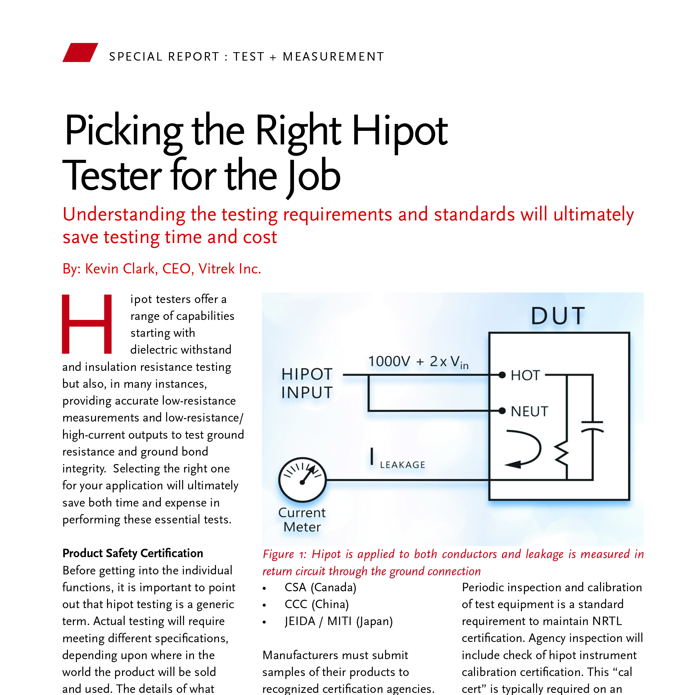
Hipot testing applies a high voltage between isolated sections of a product to verify dielectric strength. It is designed to expose insulation weaknesses that could lead to breakdown. Insulation resistance testing measures the resistance of insulation, usually with a DC test voltage, to evaluate how effectively current is blocked across an isolation barrier. Leakage current testing, by contrast, usually evaluates the current that flows while the product is powered as intended, using measurement methods tied to user or patient exposure paths.
A product can pass hipot because the insulation withstands an elevated stress for a short interval, yet still produce excessive leakage in normal operation due to filter design or parasitic coupling. Likewise, a good insulation resistance value does not automatically guarantee acceptable touch current. These tests complement each other. They answer different questions.
For engineering teams building a safety test strategy, the practical takeaway is simple: do not treat leakage current as a reduced-voltage substitute for dielectric tests, and do not assume one passing result covers the others.
Standards define the test, not just the limit
When engineers search what is leakage current testing, they often expect a universal numeric threshold. In practice, the method is defined by the standard first, and the pass limit comes with it.
IEC and UL frameworks for information technology equipment, medical electrical equipment, laboratory instruments, household appliances, and other product categories all approach leakage with specific terminology and test circuits. Medical standards are a clear example of why this matters. Patient leakage measurements use defined networks, operating conditions, and fault states because patient exposure paths are not equivalent to ordinary touch current.
The result is that leakage current testing cannot be fully separated from product classification. The same measured value may be acceptable in one category and unacceptable in another. Even within a category, applied part type, protection class, and intended environment may change the limit. Experienced test managers know that the first step is not selecting a tester. It is confirming the applicable standard and required measurement method.
Common causes of leakage current failures
Most leakage failures trace back to a short list of design or manufacturing realities. EMI suppression capacitors are one of the most frequent contributors, especially in AC line-powered systems. Power supplies with high parasitic capacitance between primary and secondary can also drive leakage upward. Cable routing, shield termination, contamination, moisture ingress, damaged insulation, and grounding errors are other common causes.
Production issues tend to be less subtle. A misplaced wire, wrong component value, loose earth bond, or assembly damage can shift leakage enough to fail final test. In service environments, aging components and contamination often change the baseline over time.
The right response depends on the source. If the issue is architectural, the design may need different filtering, shielding, isolation, or grounding strategy. If the issue is process-related, tighter production controls or end-of-line screening may be more effective than redesign.
Choosing equipment for leakage current testing
A leakage current test setup needs more than sensitivity. It needs repeatability, standard-aligned measurement networks, appropriate switching capability, safe operation, and data integrity. In production, throughput and fixture integration matter. In R&D or compliance labs, configurability and traceable measurement performance often matter more.
This is also where under-specifying instrumentation creates avoidable uncertainty. If a tester cannot reproduce the required test conditions or automate the required fault states, the measurement may be difficult to defend during validation or audit. For organizations working in regulated industries, that risk is usually more expensive than the instrument itself.
Vitrek users often face this exact requirement set: accurate electrical safety measurements, repeatable workflows, and equipment that supports serious compliance work rather than approximate screening.
Where leakage current testing fits in the workflow
Leakage current testing is most effective when it is not treated as a last-minute compliance gate. During design, it helps engineers identify trade-offs early, especially in power architecture and filtering. During validation, it confirms performance against the correct standard under the required conditions. In production, it acts as a screening tool for assembly defects and unit-to-unit variation. In service, it can support periodic safety verification and fault investigation.
That broader role is worth keeping in mind. Leakage is not just a test result to file away. It is a signal about how the product behaves electrically under real operating conditions.
If you are evaluating a device and asking what is leakage current testing, the practical answer is this: it is the disciplined measurement of unintended current paths that determine whether an energized product is merely functional or genuinely safe for its intended use.

How to Configure Digitizer for Transient Capture
A transient event rarely gives you a second chance. Whether you are capturing a switching spike in a power stage, a pulsed RF response, an intermittent fault on a bus, or a discharge event in a high-voltage test setup, the way you configure digitizer for transient capture determines whether you get usable evidence or an incomplete waveform.
Transient acquisition is not mainly about selecting the highest sample rate and pressing run. In regulated and performance-critical environments, configuration choices affect timing accuracy, amplitude fidelity, repeatability, and the ability to defend test data later. The right setup starts with the event itself – how fast it is, how often it occurs, what amplitude range it occupies, and what part of the record matters most.
What transient capture demands from the instrument
A transient has three defining traits: it is brief, often unpredictable, and easy to distort. That means the digitizer must be configured as a system, not as a collection of isolated settings. Sample rate, analog bandwidth, input range, trigger strategy, memory allocation, and clock stability all interact.
If one setting is wrong, the waveform may still look plausible while being quantitatively wrong. A clipped pulse can be mistaken for saturation in the device under test. Too little bandwidth can smooth a fast edge and hide ringing. Too much range can bury a low-level event in quantization noise. This is why transient work demands engineering discipline rather than default settings.
Start with the transient, not the digitizer
Before changing any acquisition parameter, define the event in measurement terms. Estimate its rise time, pulse width, repetition behavior, expected amplitude, source impedance, and the amount of pre-trigger and post-trigger data you need. That information drives every major setup choice.
For example, a one-time ESD-like event and a repetitive switching transient should not be configured the same way. A repetitive event may allow equivalent-time strategies or repeated optimization. A rare intermittent failure usually requires conservative triggering, deep onboard memory, and continuous monitoring modes that preserve context before and after the trigger.
This step also clarifies the measurement objective. If you only need to know peak amplitude, the setup may prioritize dynamic range and overload margin. If you need edge timing, overshoot, settling, or frequency content, then bandwidth, clock integrity, and record length become more critical.
Configure digitizer for transient capture with the right sample rate
Sample rate is the first setting most users reach for, but it should be chosen with intent. The minimum rate must satisfy the analog content of the transient, not just its duration. As a practical rule, engineers often start with at least five to ten samples across the fastest feature they need to characterize. For precision edge analysis, that may still be too low.
A very high sample rate is not automatically better. Higher rates reduce total capture time for a fixed memory depth, and they can increase data volume and downstream processing load. If the event includes a long settling period or if pre-trigger history matters, excessive sample rate can waste memory on detail that does not improve the result.
The best approach is to estimate the highest significant frequency component or the shortest edge of interest, then choose a rate that preserves that content with margin. If you expect to compare captures across tests or stations, standardizing the sample rate can also improve repeatability and simplify analysis.
Match analog bandwidth to the physics of the event
Bandwidth and sample rate are related, but they are not interchangeable. The analog front end determines what energy reaches the ADC. If the bandwidth is too low, the digitizer cannot recover edge details no matter how fast it samples.
At the same time, opening bandwidth as wide as possible is not always the right choice. Wider bandwidth admits more noise, which can reduce effective resolution and destabilize triggering for small transients. In noisy industrial environments, limiting bandwidth to what the measurement actually needs often improves waveform quality.
A useful method is to align analog bandwidth with the fastest meaningful content of the transient, then verify whether the reduced noise floor improves interpretation. This matters in power electronics, motor drive diagnostics, and high-voltage switching, where broad-spectrum interference can mask the event of interest.
Set the input range for dynamic range without clipping
Input range is one of the most consequential settings in transient work. If the range is too narrow, the event clips and the capture is compromised. If it is too wide, the ADC uses only a small portion of its available codes, reducing effective amplitude resolution.
The trade-off is straightforward but application-dependent. In fault capture, some engineers intentionally leave more headroom because the cost of clipping is higher than the cost of lower resolution. In controlled R&D pulse measurements, where amplitude is bounded, a tighter range often produces better detail.
Also confirm termination, coupling, and probe or sensor scaling. A mismatch between source impedance and digitizer input can alter pulse shape. AC coupling can remove baseline offset but distort low-frequency content and long droop behavior. For many transient applications, DC coupling with a well-understood offset is the safer starting point.
Trigger strategy is where many captures fail
To configure digitizer for transient capture successfully, trigger setup needs as much attention as the acquisition path. A good trigger should respond to the event of interest while rejecting ordinary noise, ringing, and unrelated activity.
Simple edge triggering is often adequate for clean pulses, but complex environments may require slope qualification, level hysteresis, external trigger sources, or software-assisted event logic. If the transient is tied to a known system state, an external hardware trigger often improves repeatability by reducing ambiguity.
Pre-trigger memory is especially valuable. It lets you see what happened before the event, which is often where the root cause appears. For intermittent faults, the lead-up can matter more than the spike itself. Post-trigger allocation matters too, particularly when you need to observe recovery, settling, or secondary oscillations.
Trigger holdoff is another underused control. In repetitive systems, holdoff can prevent the digitizer from retriggering on the wrong part of a burst or on reflections after the main event.
Memory depth defines how much story you can keep
Transient capture is usually a balance between time resolution and observation window. Memory depth sets that balance. Deep memory allows long records at high sample rates, which is useful when the event is rare or when system behavior before and after the transient matters.
But large records are not free. They increase transfer time, analysis overhead, and storage requirements. In production or automated validation, record size should be large enough to preserve the event context without slowing the test cell unnecessarily.
Segmented memory can be a better answer when capturing multiple short transients separated by idle time. Instead of storing long dead periods, the digitizer records only the event windows. This approach is particularly effective for burst activity, repetitive faults, and qualification tests that need many statistically relevant captures.
Validate timing, noise, and measurement integrity
Once the first waveform appears, configuration is not finished. Verify that the capture is trustworthy. Check whether the baseline is stable, whether the pulse top is flat or unexpectedly rounded, whether ringing is physical or caused by probing, and whether repeated acquisitions align in time and amplitude.
It is also worth comparing captures at two different ranges or bandwidth settings. If the waveform shape changes significantly, the current configuration may be influencing the result. In compliance-sensitive environments, this validation step supports defensible measurement practice.
Clock quality matters as well, especially when correlating channels or comparing events across systems. For multi-channel transient analysis, timing skew, synchronization method, and reference clock stability can materially affect conclusions.
Practical mistakes to avoid
Most transient capture problems come from predictable setup errors. Users oversample without enough memory, use more bandwidth than the signal requires, trigger too close to the noise floor, or leave too little pre-trigger history to diagnose the event. Another common issue is treating the digitizer like a general-purpose oscilloscope rather than a precision acquisition instrument with configurable trade-offs.
The better workflow is iterative. Start from the expected event physics, choose conservative settings, capture several examples, and then tighten the configuration around the actual waveform behavior. That process usually produces better data than choosing maximum settings across the board.
In advanced applications, a high-speed digitizer platform with flexible triggering, deep acquisition memory, and software control can make that iteration far more efficient, particularly when the capture needs to move from bench investigation into repeatable automated test.
The useful question is not whether the digitizer captured something. It is whether the captured record preserves enough amplitude, timing, and context to support the engineering decision that comes next.
How to Verify Insulation Integrity
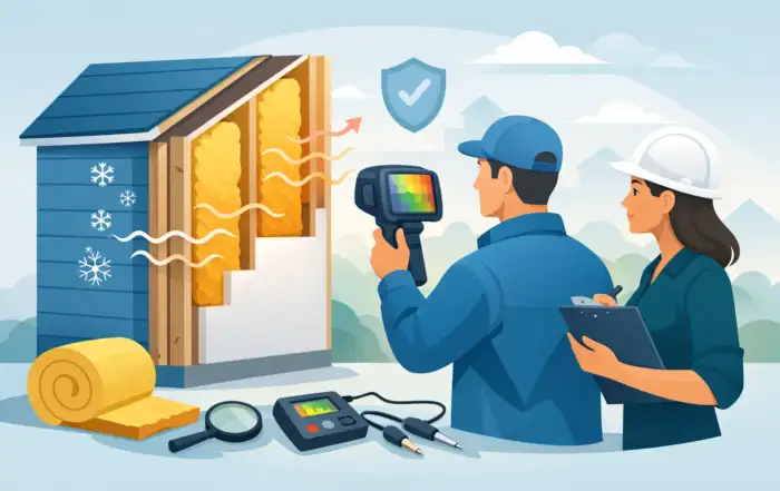
A unit that passes functional test but fails in the field often has one quiet problem: insulation that looked acceptable under casual checks and breaks down under real electrical stress. That is why engineers asking how to verify insulation integrity are rarely looking for a single reading. They need defensible evidence that insulation will withstand voltage, limit leakage, and remain reliable across production, service, and compliance environments.
What verifying insulation integrity actually means
Insulation integrity is not just the presence of high resistance between conductors and exposed metal. In regulated and high-performance systems, it is a broader question of whether insulating materials, spacings, coatings, assemblies, and interconnects continue to provide the required barrier under expected operating and fault conditions.
That distinction matters because different failure modes present differently. Surface contamination may reduce insulation resistance without immediate dielectric breakdown. A nicked wire, void in potting compound, damaged winding enamel, or moisture ingress may pass a low-stress check yet fail during hipot. Aging and thermal cycling can shift results over time, especially in motors, transformers, medical equipment, EV subsystems, and aerospace assemblies.
So when teams evaluate how to verify insulation integrity, they should define the goal first. Sometimes the goal is production screening for gross defects. Sometimes it is standards compliance. Sometimes it is failure analysis, preventive maintenance, or design validation. The correct method depends on that purpose.
How to verify insulation integrity with the right test sequence
In most applications, insulation integrity is best verified through a structured sequence rather than a single test. Visual inspection and fixture validation come first, followed by insulation resistance testing, and then dielectric withstand testing when required by the product standard or risk profile. In some cases, leakage current, ground bond, partial discharge, or high-voltage switching characterization also belongs in the sequence.
Visual inspection still matters because many insulation failures begin as assembly defects – pinched leads, inadequate creepage distance, incomplete sleeving, contamination, sharp-edge contact, or poor strain relief. If the physical build is compromised, electrical measurements may only tell part of the story.
Insulation resistance testing is often the first quantitative check. It applies a DC voltage and measures the resistance of the insulating barrier. This is useful for identifying contamination, moisture, carbon tracking, process variation, and aging. It is also less destructive than a withstand test and can be well suited for incoming inspection, maintenance, and trend analysis.
Hipot, or dielectric withstand testing, answers a different question. It applies a higher voltage – AC or DC, depending on the requirement – to verify that the insulation system does not break down under stress. A product can show high insulation resistance and still fail hipot if there is a weakness that only appears near the breakdown threshold.
For critical products, the sequence and voltage levels must align with the governing standard and the design category. Testing beyond what the product can safely tolerate may damage good units. Testing below the required stress level may create false confidence.
Insulation resistance testing: what it proves and what it does not
Insulation resistance is valuable because it is sensitive to contamination and environmental conditions, and it provides a repeatable metric for trending. Typical setups apply a defined DC test voltage between isolated conductors, conductors and chassis, or winding and frame. The measured current is converted to resistance.
The main strength of this method is sensitivity. A drifting insulation resistance value may reveal process problems well before catastrophic failure. For maintenance teams, it can show gradual degradation caused by humidity, residue, or insulation aging.
Its limitation is equally important. Insulation resistance does not directly prove dielectric strength under high transient or withstand conditions. A high megohm or gigaohm reading is encouraging, but it is not a substitute for a properly specified hipot where standards or application risk require one.
Hipot testing: verifying withstand capability
Hipot is the decisive test when the question is whether the insulation barrier can tolerate elevated voltage without flashover, arc, or excessive leakage. In production and compliance environments, this is often the required gate.
AC hipot is closer to real operating stress in many applications and captures both resistive and capacitive leakage components. DC hipot can be preferable for some products because it typically requires lower charging current and may reduce the likelihood of damaging marginal insulation during test. The trade-off is that AC and DC results are not interchangeable, and the selected method should follow the applicable standard and product design intent.
Ramp rate, dwell time, leakage limit, and discharge control all matter. An aggressive ramp or poorly controlled discharge can distort results or stress the unit unnecessarily. For assemblies with significant capacitance, test system capability becomes especially important because charging current can look like leakage if the instrument and procedure are not matched to the DUT.
Key variables that affect insulation test results
Anyone working on how to verify insulation integrity should expect the answer to include environment, fixturing, and instrument performance. Insulation measurements are highly sensitive to conditions that are easy to overlook.
Humidity is one of the biggest factors. Surface moisture lowers resistance and can create inconsistent readings across shifts or locations. Temperature also changes material behavior, sometimes significantly. If you compare results taken at different ambient conditions without normalization or controls, trends can become misleading.
Contamination is another common source of confusion. Flux residue, machining debris, fingerprints, and process chemicals can reduce insulation resistance or trigger leakage paths that are not obvious visually. In medical, aerospace, and electronics manufacturing, cleaning process validation often has a direct relationship to insulation performance.
Fixturing and guarding matter as well. Leakage through cables, adapters, test stands, or contaminated fixtures can be misread as product leakage. Proper guarding techniques help eliminate surface leakage and improve the accuracy of high-resistance measurements. This is one reason engineering-grade test systems tend to outperform generic bench setups in regulated production environments.
Pass-fail limits should come from standards and design intent
There is no universal insulation resistance value or hipot voltage that defines a good product. Acceptable limits depend on product category, working voltage, insulation type, applicable safety standard, and use environment.
For example, a medical device, EV component, industrial motor, and lab instrument may each require a different test method, stress level, and acceptance criterion. Production teams sometimes look for a simple rule of thumb, but that approach creates risk. A threshold that is too loose can miss latent defects. One that is too tight can drive false failures, rework, and unnecessary scrap.
The right approach is to start from the applicable product standard, then validate that the selected limits are appropriate for the design, materials, and expected operating conditions. If no specific standard governs the assembly, engineering teams should document the rationale for test voltage, leakage limits, dwell time, and any environmental controls. That documentation becomes essential for repeatability, audits, and root-cause investigations.
Building a repeatable verification process
The most reliable way to verify insulation integrity is to treat it as a controlled measurement process, not just a station on the line. That means calibrated instrumentation, traceable procedures, validated fixtures, and operator guidance that reduces setup variation.
A strong process also separates screening from diagnosis. In production, the objective may be fast pass-fail decisions with clear safety controls and automated data capture. In the lab, the objective may be deeper characterization across temperature, humidity, aging cycles, and failure conditions. Mixing those goals into one procedure often weakens both.
Data review is part of the process. A unit that barely passes may deserve attention if its result sits outside normal process variation. Trend data often reveals more than isolated pass-fail outcomes, especially in high-volume manufacturing or long service intervals. This is where test systems with stable measurement performance and disciplined reporting add practical value.
For organizations working in compliance-heavy sectors, the instrumentation itself matters. High-voltage accuracy, current measurement resolution, ramp control, interlock design, and repeatability all influence whether the result can be trusted. That is one reason teams often standardize on purpose-built safety test platforms from suppliers such as Vitrek when the cost of uncertain data is high.
When insulation integrity appears good but risk remains
Some insulation problems are intermittent. Vibration, thermal expansion, altitude, contamination buildup, or harness movement may create failures that static bench tests do not capture. If the field symptom is real but standard tests look clean, broaden the verification plan.
That may include testing after environmental conditioning, repeating measurements at temperature extremes, increasing fixture realism, or evaluating adjacent failure mechanisms such as ground bond weakness or transient overstress. In wound components and high-density assemblies, partial discharge or localized void-related breakdown may also deserve attention if conventional tests are not telling the full story.
The practical point is simple: insulation integrity is not verified by checking a box. It is verified when the test method matches the failure risk, the limits match the standard and the design, and the data is repeatable enough to support a technical decision.
If you are refining your approach, start by asking a harder question than pass or fail: what insulation failure are we actually trying to detect, under what stress, and with what level of confidence? That question usually leads to a better test plan than any default setting ever will.

How to Reduce Test Uncertainty
A product that passes in one lab and fails in another usually does not have a product problem first. It has a measurement problem. If your team is working out how to reduce test uncertainty, the fastest gains rarely come from a single instrument upgrade alone. They come from tightening the entire measurement chain – method, fixture, environment, operator practice, calibration, and data treatment.
In regulated and performance-critical environments, uncertainty is not an academic footnote. It affects guardbanding, yield, compliance decisions, root-cause analysis, and customer confidence. The practical objective is not to chase zero uncertainty, which is unattainable. It is to reduce uncertainty to a level that supports valid decisions with known risk.
What test uncertainty actually includes
Test uncertainty is the quantified doubt associated with a measurement result. In production and validation settings, that doubt can come from several sources acting together. Instrument accuracy matters, but so do resolution, drift, noise, lead effects, environmental variation, fixture repeatability, timing, software scaling, and operator influence.
A common mistake is to treat the instrument datasheet as the whole uncertainty budget. It is only one term. If the DUT is sensitive to temperature, if your switching path adds leakage, or if your timing window is inconsistent, the actual uncertainty seen by the test system can be materially higher than the published instrument specification.
That distinction matters most when tolerance bands are tight. A measurement system may be suitable for troubleshooting but not for compliance testing. It may also be acceptable for incoming inspection and still be inadequate for final release. The right question is always application-specific: uncertainty relative to what limit, under what conditions, and for what decision.
How to reduce test uncertainty at the system level
The most reliable way to reduce uncertainty is to stop optimizing one component in isolation. A high-performance analyzer connected through unstable fixturing or poor cabling will still produce suspect data. A well-written procedure run on drifting equipment will do the same.
Start by mapping the full measurement path from DUT output to final reported result. Include sensors, probes, switching, signal conditioning, digitization, software calculations, and report formatting. Then identify where error is introduced, amplified, or hidden.
In many systems, the largest contributors are not where teams initially expect them to be. Contact resistance, grounding errors, leakage current paths, bandwidth limitations, digitizer sampling assumptions, and thermal settling often create more variation than nominal instrument accuracy. Until those sources are visible, improvement efforts tend to be expensive and incremental.
Choose instrumentation that matches the decision you need to make
Instrument selection should begin with required uncertainty at the test point, not with a broad preference for higher specification equipment. There is a trade-off here. Overbuying performance can increase capital cost without improving the decision if fixturing or environmental control remains the dominant error source.
That said, under-specifying the instrument creates problems that no amount of procedural discipline can fix. If the ratio between instrument uncertainty and product tolerance is too high, guardbands become restrictive and false failures rise. For high-voltage, low-current, power analysis, insulation resistance, or precision displacement work, application-fit matters as much as headline specification.
Look closely at operating range, warm-up behavior, drift, input impedance, noise floor, bandwidth, sample rate, and switching characteristics. Also review how specifications are stated. Some are time-limited after calibration, some are temperature-dependent, and some only apply under narrow conditions. Engineers should build uncertainty assumptions from the exact use case, not from best-case catalog numbers.
Control fixturing, cabling, and switching
Test fixtures are often treated as accessories when they should be treated as metrology components. Mechanical instability, worn contacts, poor shielding, parasitic capacitance, and leakage paths can shift readings enough to distort pass/fail outcomes.
If you are evaluating how to reduce test uncertainty in automated systems, inspect the path between instrument and DUT with the same discipline used for the DUT itself. Use appropriate cable quality and length, maintain connector integrity, minimize unnecessary adapters, and verify that switching hardware does not compromise the signal being measured. In high-voltage or low-level current applications, insulation quality, guarding, and layout become especially important.
Repeatability testing of the fixture itself can reveal whether variation is coming from the product or from the interface to the product. When results move after reseating the DUT, the fixture is part of the uncertainty budget whether it appears on the report or not.
Calibration helps, but only if it matches use conditions
Calibration is necessary, but it is not a blanket guarantee of low uncertainty. A recently calibrated instrument can still be unsuitable for a given test if the calibration scope does not align with the operating range, environmental conditions, or required measurement function.
What matters is traceable calibration combined with verification at the points that matter most to your process. If your critical measurements happen near the low end of a range, verify there. If your safety test depends on high-voltage switching integrity, verify the switched path, not just the source instrument in isolation.
Interval setting also deserves attention. Annual calibration may be appropriate for one instrument class and too long for another depending on usage, transport, thermal stress, and risk tolerance. Shortening the interval has a cost, but so does using an instrument whose drift is unknown between service events.
For teams operating under formal quality systems, uncertainty statements from calibration providers should feed directly into internal test uncertainty budgets. That creates a more defensible basis for audit readiness and limit decisions.
Standardize the method before chasing more decimal places
Many uncertainty problems are procedural. Different operators use different settle times. Different stations apply different lead dress. Firmware versions change scaling. Software rounds values differently than the instrument display. Each variation may appear minor on its own, but together they create avoidable spread.
A strong test method defines setup, warm-up, environmental conditions, range selection, timing, fixture orientation, operator actions, calculation method, and acceptance logic. It should also state what to do when readings are unstable or when the DUT behavior is borderline. Ambiguity increases uncertainty because it turns repeatability into a matter of judgment.
Where possible, automate the sequence. Automation does not eliminate uncertainty by itself, but it reduces operator-dependent variation and improves consistency of timing and data capture. The trade-off is that automated systems need controlled software revision practices and periodic validation. A hidden script change can shift results just as easily as a hardware issue.
Manage environmental effects explicitly
Temperature, humidity, vibration, EMI, and power quality all affect test integrity. Some DUTs are highly sensitive to these variables, and some instruments are more tolerant than others. In both cases, uncontrolled conditions increase measurement spread.
The right level of control depends on the application. A production floor may not need laboratory-grade environmental isolation, but it does need defined operating limits and monitoring. If your uncertainty budget assumes 23 C and stable humidity while the line routinely operates outside that band, the budget is optimistic.
Environmental management can be straightforward: warm-up discipline, stable power, shielding, grounded layouts, separated noisy loads, and clear criteria for when to pause testing. These are not secondary details. They often determine whether a system performs like its specification or like its worst day.
Use data analysis to find hidden contributors
If measurement spread remains stubborn after instrument and method reviews, look at the data structure. Trend by station, operator, fixture, ambient condition, time since calibration, and DUT family. Bias and variance often become obvious once data is grouped in a useful way.
Gauge repeatability and reproducibility studies can help, but only if they reflect real operating conditions. A sanitized study on ideal samples may miss the instability seen with actual products. The goal is not to produce a perfect chart. It is to identify which contributors are large enough to change business decisions.
This is also where false precision should be removed. Reporting more digits than the system can support does not improve confidence. It hides the need for better uncertainty discipline.
Reduce decision risk, not just numerical uncertainty
The final purpose of uncertainty work is better decisions. In some applications, that means reducing false failures and unnecessary rework. In others, it means avoiding false passes in safety, medical, aerospace, or defense programs where the consequence is much higher.
That is why guardbanding, specification limits, and uncertainty should be reviewed together. A tighter guardband may improve protection against bad escapes but hurt yield. A looser one may increase throughput while raising risk. The right choice depends on product criticality, compliance exposure, process capability, and customer requirements.
Organizations that perform this well treat uncertainty as part of system design, not post-test cleanup. They select instruments and fixtures around the decision threshold, verify the full measurement path, maintain traceability, and continuously watch for drift in both hardware and method. That discipline is where measurement confidence comes from.
If your test results are driving release, certification, or safety decisions, reducing uncertainty is less about buying a better box and more about building a better measurement process. That is the point where test data becomes something your team can act on without hesitation.

How to Validate Leakage Current Measurements
A leakage current reading that looks reasonable is not the same as a leakage current reading you can defend. In safety, compliance, and product validation work, the question is not only how to validate leakage current measurements, but how to prove that the value reflects the device under test rather than the test setup, instrument limits, or environmental noise.
Leakage current validation matters because the measurement sits at the intersection of product safety, regulatory requirements, and instrument performance. Small setup errors can shift results enough to trigger false failures, hide a real safety issue, or create unnecessary engineering churn. When teams treat validation as a formal measurement discipline instead of a quick confidence check, they get data that holds up during design reviews, audits, and certification testing.
What validation really means in leakage current testing
Validating a leakage current measurement is not a single action. It is the process of confirming that the instrument, fixture, method, and operating conditions produce results that are accurate, repeatable, and appropriate for the applicable standard.
That distinction matters. A calibrated tester can still produce invalid results if the wrong measuring network is selected, if fixture capacitance is too high, if grounding is inconsistent, or if the applied voltage does not match the intended test condition. Calibration confirms instrument performance against a reference. Validation confirms that the full measurement process is fit for use.
For engineering teams, that usually means answering five questions. Is the tester operating within traceable calibration? Is the measurement method aligned with the governing standard? Is the setup minimizing parasitic effects and external interference? Are the results repeatable across runs and operators? And does the observed value make physical sense for the product under test?
How to validate leakage current measurements in practice
The most reliable approach starts before the first reading is taken. Define the test objective first. Production screening, design verification, failure analysis, and formal compliance testing can all involve leakage current, but they do not always use the same limits, operating modes, or confidence thresholds.
Next, confirm the standard and measurement model. Medical electrical equipment, consumer products, industrial assemblies, and EV subsystems may reference different leakage current methods and body model networks. If the standard specifies a measuring device, supply configuration, polarity sequence, fault condition, or frequency range, those details are part of the measurement. Skipping them invalidates the result even if the number appears stable.
Then verify the instrument configuration. Range selection, bandwidth, filter settings, integration time, source voltage, and current measurement path all affect the reading. Leakage current is often low enough that instrument noise, zero offset, and coupling from nearby conductors become relevant. If the tester supports guard functions or configurable networks, confirm that these are set intentionally rather than left at prior test defaults.
A practical validation step is to use a known reference path that simulates expected leakage. This can be a traceable resistance or impedance standard, or a carefully characterized validation fixture designed for the applicable method. The point is not to reproduce every behavior of the DUT. It is to confirm that the system measures a known current correctly under the same source and network conditions used in the actual test.
Start with calibration, but do not stop there
Traceable calibration is the floor, not the ceiling. The instrument should have a current calibration appropriate to the expected measurement range, and the calibration interval should match the risk profile of the application. In regulated environments, documentation matters as much as the certificate itself. Teams should be able to show calibration status, reference standards, uncertainty, and any relevant as-found or as-left data.
Even so, a recent calibration does not remove the need for an operational check. Leakage current testers can be affected by cable changes, worn fixtures, contamination, software updates, or operator setup differences. A short verification routine at the start of a shift or test campaign often catches these issues faster than troubleshooting after a batch of suspect results.
This is where engineering discipline pays off. If a tester passes calibration but fails an in-house reference check, the issue is usually in the setup, not the metrology lab. That is exactly why validation needs to include the whole measurement chain.
Control the setup variables that distort low-level current readings
Leakage current measurements are especially sensitive to parasitics. Long leads add capacitance. Routing test cables next to high-voltage lines can introduce coupling. Bench grounding can create alternate return paths. Humidity, contamination, and fixture insulation condition can all increase apparent leakage.
For that reason, the physical test arrangement should be treated as part of the instrument. Keep cable lengths controlled and documented. Use fixtures with known insulation properties. Clean surfaces that can accumulate conductive residue. Maintain consistent grounding and shielding practices. If the DUT has multiple operating modes or floating sections, validate each relevant configuration rather than assuming one setup covers all cases.
Warm-up time also matters more than many teams expect. Source stability, internal offsets, and DUT dielectric behavior can all change during the first several minutes of operation. If your readings drift before settling, that is not just a nuisance. It is a sign that the method needs a defined stabilization period.
Repeatability and reproducibility are part of validation
A single correct-looking result is weak evidence. Validation should include repeated measurements under the same conditions to assess repeatability, and where practical, checks across operators, fixtures, or stations to assess reproducibility.
If the data spread is large relative to the acceptance limit, the process is not validated even if the average value is close to expectation. In those cases, teams should look at instrument resolution, environmental noise, fixture consistency, and DUT state control. Some products inherently show variation because of capacitive charging, switching behavior, or power supply topology. That is acceptable if the variation is understood and bounded. It is a problem if no one can explain it.
A useful practice is to document a baseline mean and spread for representative products or golden units. Over time, that gives test engineering a way to distinguish true DUT changes from station drift.
Use uncertainty as a decision tool, not a paperwork exercise
When engineers ask how to validate leakage current measurements, they often mean how much confidence is enough to make a release or compliance decision. That is an uncertainty question.
Measurement uncertainty in leakage current testing can come from instrument accuracy, range resolution, line voltage stability, measuring network tolerance, fixture effects, environmental conditions, and DUT variability. Not every application requires a full formal budget, but high-consequence testing should quantify the major contributors.
This becomes critical when measured values are near the specification limit. If a product measures 0.48 mA against a 0.50 mA limit, pass or fail cannot be determined responsibly without considering uncertainty and the decision rule being applied. In production environments, guardbands may be appropriate. In compliance work, the relevant standard or certification body may dictate how limits are interpreted.
The discipline here is straightforward. Know the expanded uncertainty of the measurement process, understand the acceptance rule, and avoid making binary decisions from marginal data without context.
How standards alignment affects validation
One of the most common causes of disputed leakage current results is not instrument error but method mismatch. Different standards can define different measuring devices, supply conditions, fault simulations, and touchpoint arrangements. Two competent labs can test the same product and report different values if their setups are not equivalent.
That is why standards alignment should be verified as part of validation, not assumed. Confirm the required network, source frequency, source impedance, polarity switching, ground condition, and any normal or single-fault scenarios. If software controls the sequence, review the programmed steps against the written method. A small configuration mismatch can create a large disagreement, especially for products with EMI filters, Y capacitors, or switching power architectures.
For organizations managing multiple product categories, standardized work instructions and prevalidated test methods reduce this risk substantially. This is also where purpose-built safety test platforms from experienced suppliers such as Vitrek can help by providing tighter control over source conditions, measurement functions, and repeatable execution.
Document enough to make the result defensible
Validation is only useful if another engineer can review the record and understand what was proven. At a minimum, document the instrument identification, calibration status, method used, fixture configuration, environmental conditions if relevant, reference check results, and repeatability observations. If uncertainty or guardbanding influences the disposition, record that logic clearly.
The best validation records are not longer than necessary. They are specific. If a reading later becomes part of a failure investigation, supplier dispute, or audit trail, clear documentation saves far more time than it takes to create.
A well-validated leakage current measurement gives engineering teams more than a number. It gives them confidence that the number means what they think it means, which is exactly what high-stakes testing demands.

Electrical Safety Test Automation Workflow
When a production line fails a compliance audit, the problem is often not the hipot or ground bond test itself. It is the gap between the instrument, the operator, the product variant, and the record that proves the test was run correctly. A well-designed electrical safety test automation workflow closes that gap by making test execution, decision logic, and data capture consistent from unit to unit.
For manufacturers in medical devices, EV subsystems, appliances, industrial controls, and defense electronics, that consistency matters for more than throughput. Electrical safety testing sits at the intersection of operator safety, product certification, and traceable quality records. If the workflow is loosely defined, even a capable instrument can become part of a brittle process. If the workflow is engineered correctly, automation can reduce retest rates, tighten compliance, and make failures easier to diagnose.
What an electrical safety test automation workflow really includes
In practice, the workflow is more than a script that triggers a hipot sequence. It includes test selection, product identification, fixture interlocks, parameter control, operator prompts, pass-fail logic, results storage, and exception handling. In regulated environments, it also includes calibration status, user access control, and the ability to show that the right limits were applied to the right product revision.
That broader definition matters because many automation efforts stall when teams focus only on instrument command sets. Sending remote commands over LAN, USB, or GPIB is the easy part. The harder part is building a repeatable process around product variation, operator behavior, and documentation requirements.
A practical workflow usually starts before voltage is applied. The system needs to know what is being tested, what standard or internal specification applies, what fixture is connected, and whether all safety conditions are met. Only then should the sequence proceed to dielectric withstand, insulation resistance, ground continuity, leakage current, or other required tests.
Why manual electrical safety testing breaks down at scale
Manual methods can be acceptable in low-volume engineering validation, especially when experienced technicians are working through early design iterations. In production, the same approach creates avoidable risk. Operators may select the wrong program, skip a prompt, misread a fixture status, or record results in a disconnected database hours later.
The cost of those mistakes is not limited to scrap. A false fail reduces throughput and drives unnecessary troubleshooting. A false pass is more serious because it can affect certification status, field reliability, and user safety. Even when the measured values are correct, poor data handling can leave the organization unable to demonstrate compliance during an audit or customer review.
Automation addresses these issues, but only if the process accounts for edge cases. A workflow that speeds up normal operation while ignoring rework handling, barcode errors, or fixture wear will simply move the bottleneck.
Building the workflow around the product and the standard
The best starting point is the test requirement, not the software interface. Engineers should map each product family to its applicable safety standards, internal limits, and manufacturing constraints. That means defining the exact test types, voltage levels, ramp times, dwell times, current limits, and pass-fail thresholds, along with any sequencing rules.
This is also where trade-offs appear. A single universal test sequence may simplify administration, but it can be inefficient for mixed-product lines. Product-specific sequences improve cycle time and control, but they add configuration management overhead. The right choice depends on volume, revision frequency, and how often test limits change.
Once requirements are stable, the workflow can be organized into a controlled sequence. Product identification should call up the correct test recipe automatically. Fixture verification should confirm that the intended DUT connection is present. Interlocks should prevent unsafe initiation. The instrument should execute the sequence with locked parameters rather than relying on operator entry. Results should be written directly to a traceable record with timestamps, serial numbers, operator IDs, and equipment IDs.
Key elements of an effective electrical safety test automation workflow
Instrument control and parameter integrity
The workflow should treat test parameters as controlled data. If operators can modify limits on the fly, repeatability suffers and audit exposure increases. A better approach is role-based access with approved recipes maintained under revision control.
Instrument integration should also support positive confirmation that the loaded program matches the intended product. In higher-risk applications, teams often add checksum validation or recipe approval logic in the supervisory software to reduce the chance of running an outdated configuration.
Safety interlocks and fixture awareness
Electrical safety automation must protect the operator first. That means door switches, dual-action start controls where appropriate, emergency stops, discharge verification, and fixture presence checks. For high-voltage testing, the workflow should explicitly handle charge dissipation before allowing part removal.
Fixtures deserve more attention than they usually get. A worn probe, contaminated contact surface, or intermittent ground path can create unstable results that look like product defects. Many false failures originate in fixturing, not the DUT. Building fixture validation into the workflow can save significant debugging time.
Data capture and traceability
A pass indicator alone is not enough. The workflow should capture the measured values, the limits applied, the instrument used, calibration status, the software revision, and the product identifier. In some environments, waveform or event-level detail is also useful, especially when troubleshooting intermittent breakdowns or leakage behavior.
This record structure becomes more valuable over time. It supports root-cause analysis, process capability studies, customer documentation, and audit response. It also helps test managers distinguish between a real product shift and a measurement-system problem.
Exception handling
Most systems are designed for the ideal path. Strong workflows are designed for the non-ideal one. What happens when a barcode does not scan, a test aborts mid-cycle, network storage is unavailable, or the DUT fails the first step? The workflow should define what gets blocked, what gets logged, and what actions require supervisor approval.
Without that logic, operators invent local workarounds. Those workarounds may restore output in the short term, but they weaken control of the process.
Integration choices depend on production reality
Some operations need a fully integrated station tied to MES, ERP, and plant historians. Others need a self-contained cell that exports validated records at the end of a shift. There is no single correct architecture.
For high-volume manufacturing, direct integration with factory systems can reduce transcription errors and support real-time containment when failures trend upward. For lower-volume or high-mix environments, a more modular setup may be easier to validate and maintain. The trade-off is usually between central visibility and local flexibility.
The same applies to software strategy. Off-the-shelf test executive platforms can speed deployment, especially when teams need standard UI elements, reporting, and instrument drivers. Custom software may be justified when product logic, fixture control, or cybersecurity requirements are unusually specific. In either case, the design should prioritize deterministic behavior, maintainability, and validation discipline over feature count.
Common implementation mistakes
One common mistake is automating an unstable manual process. If the original test method has unclear fixturing, inconsistent contact quality, or loosely defined limits, software will not fix it. It will only make the inconsistency happen faster.
Another is ignoring measurement uncertainty and instrument capability. A workflow can be technically automated and still be poorly matched to the test requirement. Voltage accuracy, current resolution, discharge behavior, switching characteristics, and timing control all affect whether the data is trustworthy.
A third mistake is treating reporting as an afterthought. If result records are not structured correctly from the start, teams often end up with data they cannot search, compare, or defend during an audit. That is particularly costly in regulated industries where proof of process control matters as much as the individual pass-fail result.
What improvement should look like
A successful automation project should reduce operator dependence without reducing engineering visibility. Throughput should improve, but not at the expense of test rigor. Failure analysis should get easier because the system captures more context, not less.
In many cases, the first measurable gains are fewer setup errors, more consistent cycle times, and better traceability. Larger gains often come later, after teams use the accumulated data to refine limits, detect fixture degradation, and identify product design issues earlier in the process. That is where an engineering-grade platform, such as those developed by Vitrek for electrical safety and high-voltage test environments, can make the workflow more dependable over the long term.
The strongest electrical safety test automation workflow is not the one with the most screens or the most integration points. It is the one that applies the right test, in the right order, under controlled conditions, and leaves behind a record that can stand up to engineering review and compliance scrutiny. If you build the workflow around that standard, automation becomes a quality control tool rather than just a faster button press.
Education & Training
Check out our recent presentation of Understanding Electrical Safety Testers at the 2018 San Diego Test Equipment Symposium!