
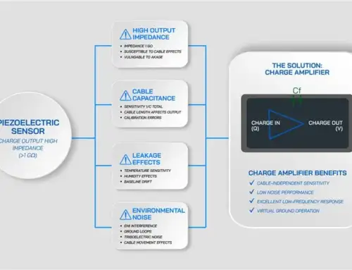
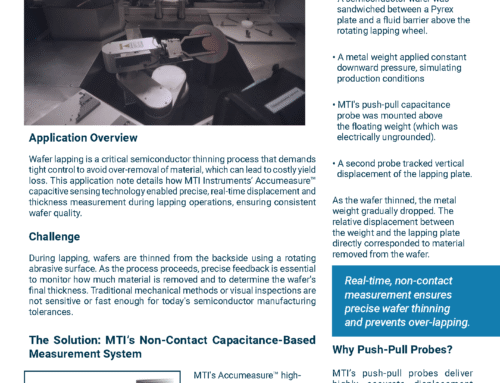
Easy Roller Gap Measurement Ensures Calendering Success
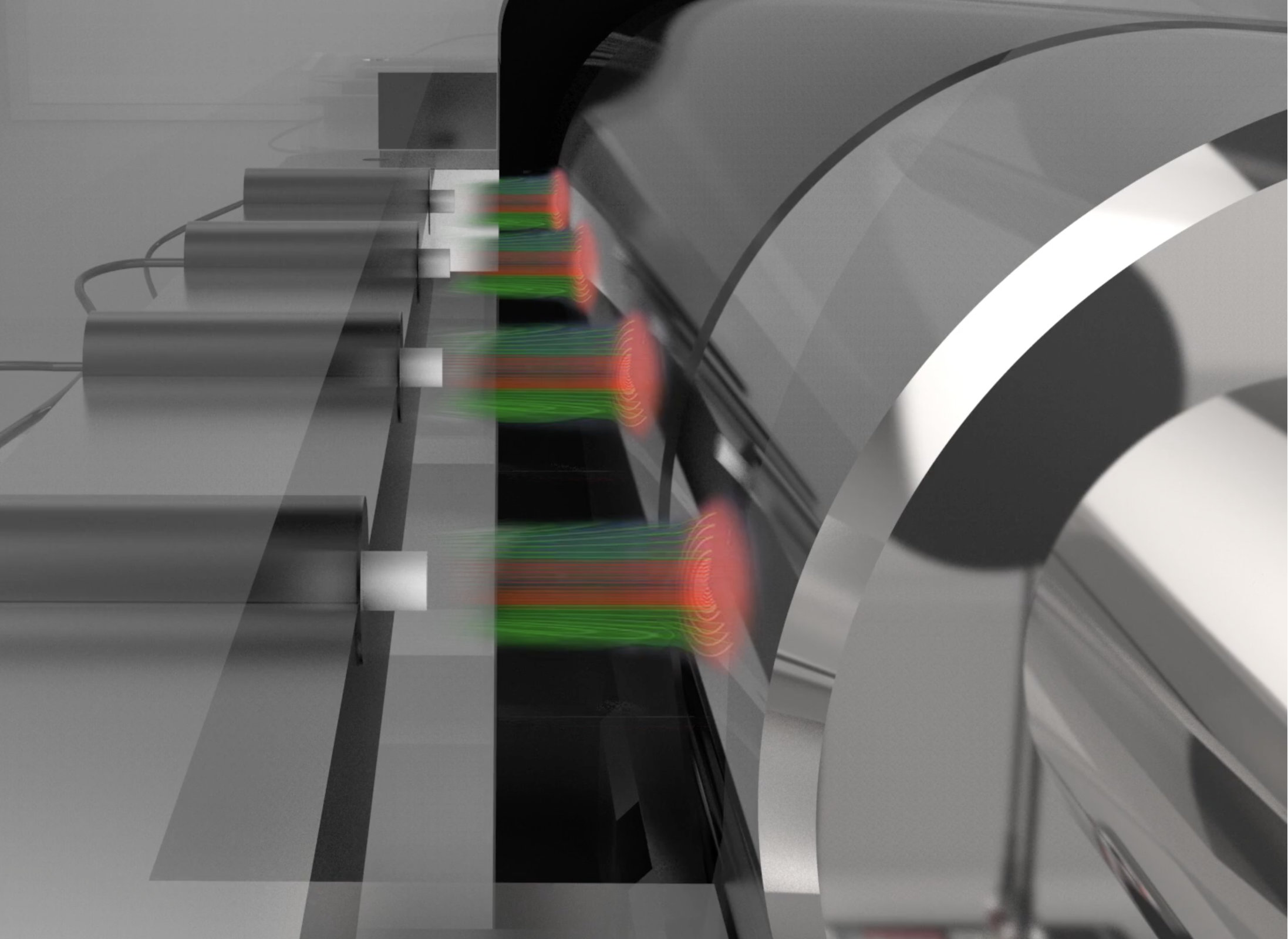
Many roll-to-roll finishing processes typically use a calender, or series of hard pressure rollers, to deliver smooth, high-quality products of plastic, textile, or paper (Fig 1). Ensuring a consistent material thickness, however, depends on the ability to monitor, and maintain, a precise gap between rollers. This application note describes a quick and easy means for roller gap measurement

Problem
Establishing a roller gap and checking for parallelism across roller width can be a slow and cumbersome procedure. Manual measurement requires multiple sized feeler gauges which can introduce errors. Misinterpreting feeler gauge drag, for instance, can lead to an incorrect gap reading. Accidentally tilting the feeler gauge can also result in a gap measurement error.
Maintaining a precise roller gap is also cumbersome as operating conditions may exacerbate or add to measurement errors. For example, excessive bearing play can lead to out-of-round conditions (Fig 2). This run out must be corrected – often requiring bearing replacement – and the gap measured all over again.

Figure 2. The ability to monitor gap parallelism in real time can prevent unintentional out-of-round situations.
Solution
MTI’s capacitive gap measuring probes eliminate the need for mechanical feeler gauges. Users quickly measure the gap between rollers electronically – as well as roller parallelism, roundness, and bearing run out – simply by positioning the probes at several lateral locations across the rollers.
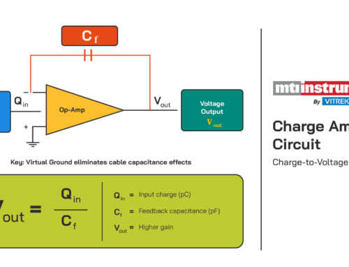
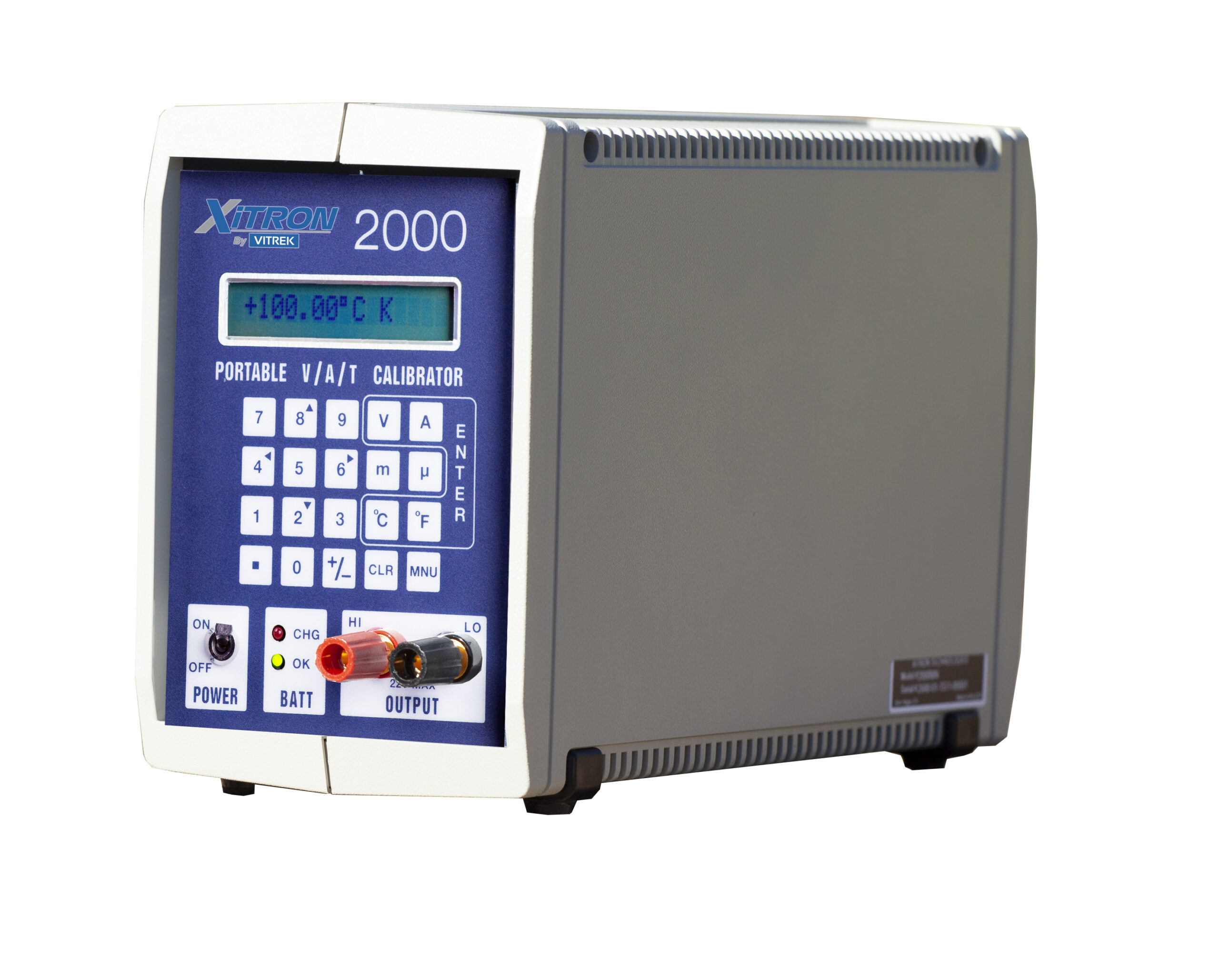
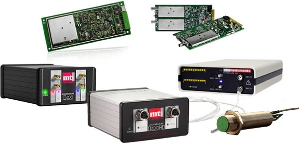
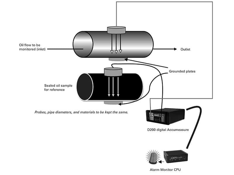
This gap monitoring system includes two components: a Digital Accumeasure amplifier (Fig 3) and gap monitoring wand (Fig 4). The wand contains two opposing capacitance probes, one per roller. Each probe/roller sets up a classic two-plate capacitive gap sensor (Fig 5).

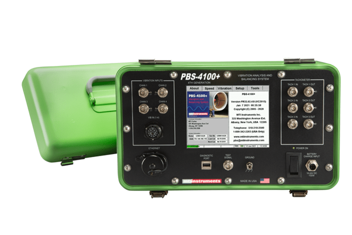
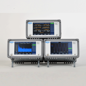
Figure 3. MTI Instruments Accumeasure D400 amplifier with four independent measurement channels.

Gap monitoring wand containing two opposing capacitive gap measurement probes.

Figure 5. Gap monitoring wand inserted between rollers; capacitance probes are tangent to both roller faces. An adjustable plastic roller stops aids with depth of insertion.
To work, the amplifier injects a current into each probe, and then measures the impedance of the respective capacitive gaps. The impedance measured is directly proportional to the probe/roller gap by the formula: Gap = (area of the probe X dielectric constant of air) / (capacitance of the gap).
Summing the two probe/roller gaps, and adding the respective probe thicknesses, gives the gap between rollers. If roller grounding is poor or non-existent, a wand equipped with MTI’s Push-Pull probes can be used to make the measurements (Fig 6).

Figure 6. MTI’s Push-Pull probes feature two sensing elements built into one probe body eliminating the need to electrically ground the motor.
Benefits
• Non-contact measurement eliminates mechanical error
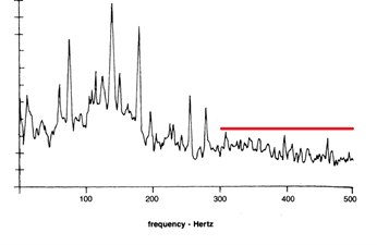
• Gap measurements can be electronically stored for future reference (Fig 7)
• The capacitance amplifier can be networked for process control and active gap control
• Real-time monitoring spots excessive bearing play

Figure 7. Plot of a changing gap as would be encountered when adjusting a roller gap.


