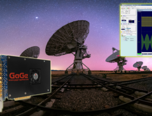
Wide Bandwidth Digitizer Provides Essential Data Processing in an Innovative Real-Time Channel Sounder for 5G Applications
By Gerald Allgaier, GaGe ( a Vitrek Brand)

Introduction
Orange Labs, the research & development division of the French telecommunications multi-national, Orange, presented a paper[1] at the 13th European Conference on Antennas and Propagation (EUCAP 2019) held in Krakow, Poland. Introduced in the paper, was an innovative wideband radio channel sounder that conducts reliable, easy-to-use measurements in demanding 5G applications, such as outdoor drive tests.
This article describes the GaGe EON Express 3 GS/s 12-bit PCIe Gen3 Digitizer that Orange Labs employed in the receiver digital part of the radio channel sounder to implement efficient data streaming functions.
Development of the 5G-Compliant Channel Sounder
The paper begins by illustrating the challenges of measuring a propagation channel in radio-mobile communication applications:
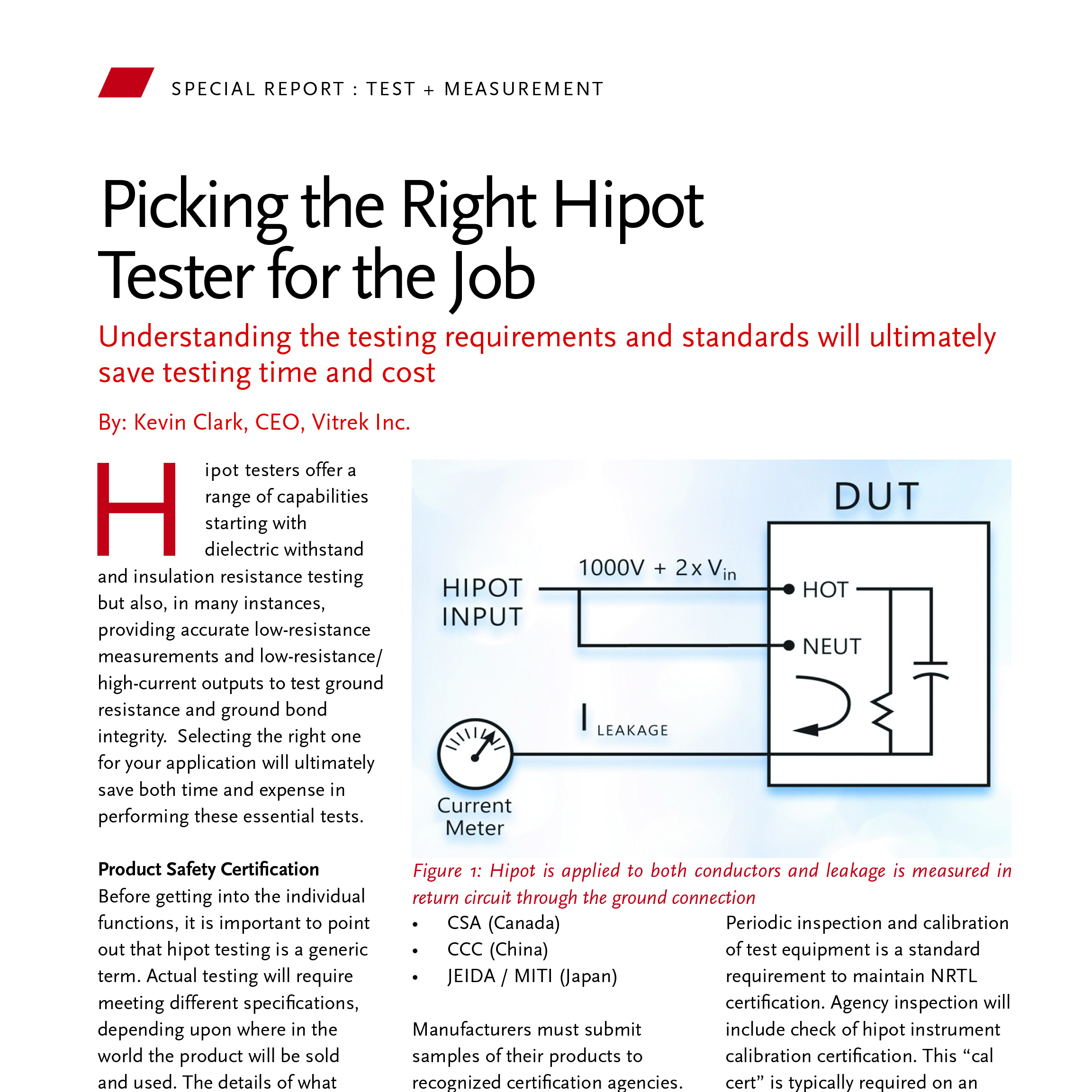
The quality of a radio-mobile communication is strongly dependent on the properties of the propagation channel. Buildings, trees or any other obstacle can attenuate, reflect, diffract or diffuse the signal transmitted from a base station. The signal received by a terminal is therefore the sum of a multitude of components that corresponds to the original transmitted signal weakened and delayed by the propagation channel. This multi-path phenomenon makes the propagation channel selective in time and in frequency, and affects the performance of wideband systems. In order to design mechanisms that correct the effects of multi-paths, the propagation channel has to be measured and characterized. A wideband channel sounder is a measurement device dedicated to the measurement of the propagation channel.[1]
The paper goes on to say that Orange Labs has developed “a new general-purpose channel sounder that may be defined as a 5G-compliant and real-time device with a simple hardware architecture.” The innovative channel sounder, it continues, “is based on off-the-shelf commercial modules in order to facilitate development and maintenance operations.”[2]
The main job for this wideband channel sounder is measuring and computing the complex impulse response of the propagation channel. This typically involves a field deployment inside a moving vehicle, with over 10,000 readings processed and stored every second. The described system measures this impulse response with a bandwidth of 800 MHz, at radio frequencies up to 30 GHz. This meets the requirements for 5G Systems operating at millimeter wave frequencies.
The receiver digital part is based on a PCIe Gen3 digitizer with special capabilities that enable real-time continuous channel sounding data to be acquired, processed, and stored in less than 75 µs. The key digitizer capabilities that enable this 800 MHz BW real-time system are:
• PCIe Gen3 interface, using x8 lanes for data transfers from digitizer to PC memory, and x8 lanes from memory to SSD storage.
• Externally triggered real-time streaming (6 GB/s continuous, 7.8 GB/s burst) with trigger time stamps (333 ps resolution).
• 44-bit trigger time counter, based on external 10 MHz reference.
• 12-bit, 3 GS/s acquisition, x 2 channels.
These are explained in more detail as follows:
The main channel sounder architecture uses 2 physically separate subsystems – the transmitter, and receiver. The transmitter computer drives an arbitrary waveform generator (AWG) to generate an IF signal with 800 MHz bandwidth, centered at the 750 MHz IF. This IF signal is then upconverted to required radio frequency, up to 30 GHz. The upconverter output is amplified and drives an appropriate antenna to transmit the test signal.
The receiver employs a matching downconverter, which is fed by the receive antenna. The downconverter outputs the 800 MHz bandwidth IF @ 750 MHz to the 12 bit, 3 GS/s digitizer input.
The Orange Labs channel sounder has 2 transmit and 2 receive channels, which it can use in the future to employ 2x2 MIMO. But at present both channels are used to compare the effects of modulation and frequency
(i.e., 3 GHz vs. 18 GHz).
A unique feature of this type of Channel Sounder is their ability to perform a complex frequency response function H(f) at the receiver, after storing a reference pulse when calibrated. When the transmitter and receiver are started, the output is connected directly to the receiver input via cable (and attenuator). This way the reference measurement includes amplitude and phase effects of both up and down conversion.
The complex reference measurement is stored in the receiver. It contains the broadband multi-sine test pulse, which is used later in H(f) Frequency Response calculations. At this startup calibration, the Rubidium timing sources are also calibrated to each other (to less than 10ns/hour drift). The dual 10 MHz references, one in each system, are used as timing references for all frequency critical functions – the LO reference in the up and down converters, and the sampling clock reference for the AWG and digitizer.
The GaGe EON Express references the internal timecode counter to the 3 GS/s sample clock. This 44-bit timecode counter, which stores this timecode value when triggers occur, is critical to identifying and correlating the timing of received pulses to transmitted pulses.
The calibration process also aligns the respective trigger counters in both transmit and receive systems, now both driven by calibrated identical 10 MHz references. The systems are then separated, and antennas connected, and testing begins. The transmit side transmits continuous pulses, whereas the receiver triggers from a vehicle sensor. This makes the receive data spaced evenly over distance, not time.
Real-time processing functions:
Acquisition samples are moved in bursts to approach maximum PCI Gen3 data rates. The data acquisition and processing PC applications are in executed in parallel using the 4 CPU cores running separate threads. The minimum trigger time interval is 75 µs. The digitized receiver signal flow and processing breaks down as follows, for a typical set of operating parameters:
• Acquire 4 triggers into digitizer memory, DMA transfer to PC, average together – 75 µs.
• Perform complex DSP functions to process data – time corrections, FFT / Transfer Function H(f), then inverse for Impulse Response – 65 µs.
• Save data to SSD Raid Array – 60 µs.
The digitizer trigger “dead time”, which is the time for the trigger circuit to reset and then be able to accept another reading, is less than 1 µs.
The system was tested at 3.7 GHz and 18 GHz, at vehicle speeds up to 30 m/s (about 67 mph).
The 12-Bit Digitizer Used in the Channel Sounder Receiver Configuration
The Orange Labs paper delves into the intricate details of this new system’s transmitter (Tx) and receiver (Rx) configurations. A critical component in the Rx hardware design is the inclusion of a GaGe EON Express, 12-bit, 3 GS/s, PCIe Gen3 Digitizer.
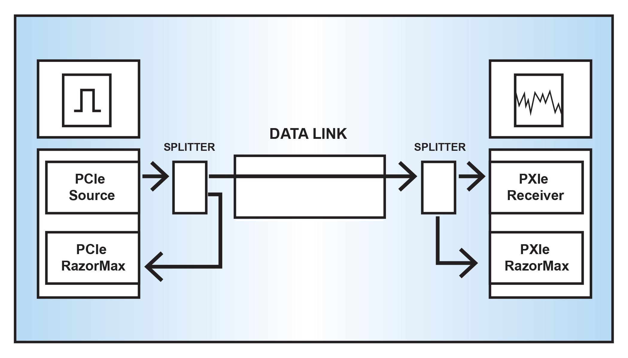
Figure 1 depicts the Rx hardware configuration set up to receive and process two RF signals transmitted from the Tx hardware. The paper indicates that this 2*2 configuration isn’t intended to perform multiple-input multiple-output (MIMO) communication but rather to perform comparison measurements. The signals produced by the transmitter system have a bandwidth of up to 800MHz on a carrier frequency ranging up to 30 GHz.
Figure 1 depicts the configuration of the system’s receiver system, showing where the EON Express digitizer is used to convert the two analog RF signals into digital data that is then analyzed using the system’s real-time processor.
As the paper reports, “The PC motherboard and the digitizer exchange data through the PCIe bus.” Figure 2 shows that ”during the measurement, an acquisition is started for each acqui-trigger and is saved in the digitizer FIFO. An acquisition contains the digitized samples from the two channels and certain internal information specific to the digitizer.”[3]

Figure 1. EON Express Digitizer converts two RF signals produced and transmitter from the channel sounder's Tx system. (Image courtesy of Orange Labs.)

Figure 2. EON Express Digitizer transfers data for real-time processing via its PCIe interface. (Image courtesy of Orange Labs).
Features of the EON Express Digitizer
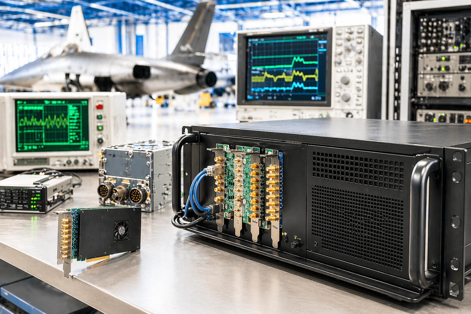
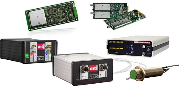
The GaGe EON Express (Figure 3) PCIe Gen 3 digitizer board features unprecedented speed and resolution. The digitizer’s capabilities are critical to the channel sounder’s performance.

Figure 3. GaGe EON Express 12-bit, PCIe Gen 3 Digitizer.
The two-channel model used in this application supports a maximum A/D sampling rate of 3 GS/s per channel. The analog input bandwidth is 1.75 GHz with ±0.5 dB flatness to 1.25 GHz. The input channels are fixed for DC-coupling with a fixed 50 Ω input impedance. Onboard auto-calibration provides DC accuracy of ±0.5%. This wide 1.75 GHz bandwidth is especially useful for RF-based applications by enabling direct RF sampling of wider band signals.
The EON Express includes 4 GB of onboard acquisition sample memory. The onboard acquisition memory size is shared and equally divided between the channels when acquiring data to onboard memory.
With the optional eXpert PCIe Data Streaming FPGA Firmware package, the dual-port architecture of the onboard memory is utilized as a large FIFO buffer for streaming acquired data to host PC memory via the digitizer’s PCIe Gen3 x8 interface at sustained rates up to 6 GB/s. This streaming mode can be effectively utilized to conduct real-time sustained host-based signal processing and/or signal recording operations of the acquired data.
[1] Jean-Marc Conrat, Orange Labs, Belfort, France. “A Real-Time Propagation Channel Sounder for 5G Applications.” Published in: 2019 13th European Conference on Antennas and Propagation (EuCAP). Added to IEEE Xplore: June 2019.
[2] Ibid.
[3] Ibid.


