
Three Vibration/Balancing Solutions for the Aviation Industry
MTI Instruments Offers a Variety of Solutions for Commercial, Regional & Military Jet Engine Balancing Applications

Introduction
Throughout the aviation industry, whether commercial or military, jet engine vibration is an everyday concern. Maintenance, repair, and overhaul crews worldwide are tasked with monitoring aircraft engine vibration to ensure flight safety and efficient service.
Gone unchecked, jet engine vibration can be the catalyst for any number of problems, from minor annoyances such as cabin noise to undue parts wear. In the most severe cases, an out-of-balance turbine could lead to catastrophic failure from metal fatigue or cracks in rotor structures.
Overall gas turbine engine vibration, however, is actually the summation of vibration contributions from a variety of moving parts within the engine. To correlate vibration magnitude with specifi c engine components, maintenance engineers rely on vibration analysis and trim balancing tools.
Vibration analysis detects discrepancies in rotational machine dynamics while trim balancing is used to reduce vibration amplitudes of gas turbine shafts. Together, they help engineers ascertain and correct individual sources of vibration within an engine.
This paper provides a quick overview of aerospace engine testing solutions for engine vibration/balancing as well as signal conditioning technology from MTI instruments.
One: An Advanced Turbine Vibration Analyzer/Balancing System
A modern turbine engine will typically contain two or three concentric shafts containing compressors, fans and turbines. These shafts are often referred to as “spools.” The spools are aerodynamically coupled, meaning each spool turns at a rate that is variable to its fellow spool. Consequently, each spool contains a speed pickup or “tachometer” so that rotational velocity and the spool rotational angle can be known.
In addition, vibration sensors are affixed to one or more positions on the engine case, measuring the magnitude of physical shaking. These built-in tachometer and vibration sensors are intended to provide a means for measuring speed and vibration as the engine operates. Reliable detection of their signals, however, is no trivial task as the signals are extremely noisy. Complicating matters further, different engines feature different signal types.
To solve this problem, manufacturers have delivered turbine vibration analyzer/balancing systems that are applicable for all engines. Some have options including a test cell version which is designed for use in a production or overhaul facility, and some also off er a lightweight “portable” system which can be used on the ground for installed engines. Both types of systems typically off er tachometer signal conditioning technology and both share the same principle of operation.

How It Works
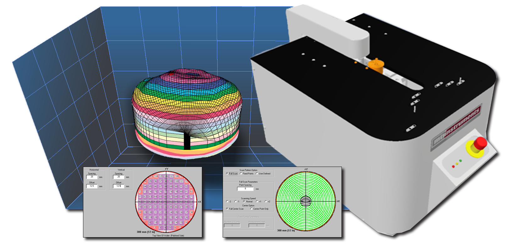
Turbine Vibration Analyzer/Balancing Systems give users the ability to check the vibration amplitude of an engine and balance that engine if necessary. It does this with a series of on-board digitizers designed to measure each spool’s rotational speed and magnitude of vibration. Embedded logic assesses the 12 o’clock position of each engine spool to understand where on the spool an imbalance might be located.
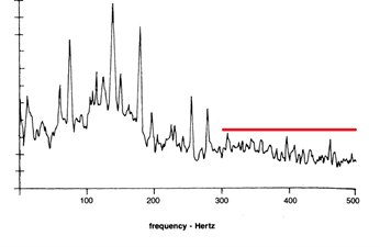
A series of configurable “tracking filters” correlates vibration to the spools. These specialized computer algorithms measure the rotational speed of a given spool and then filter the vibration content outside of a narrow band of interest. The narrow band of interest is the characteristic frequency of vibration around each spool’s rotational speed.
By using the tracking filter for each speed, the contribution of vibration of each spool can be separated. As vibration varies with engine speed, measurement data is stored and presented in vibration versus speed trend plots.
Conduct a Turbine Engine Vibration Survey
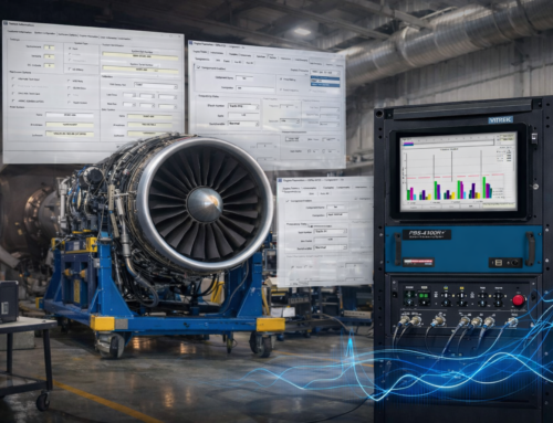
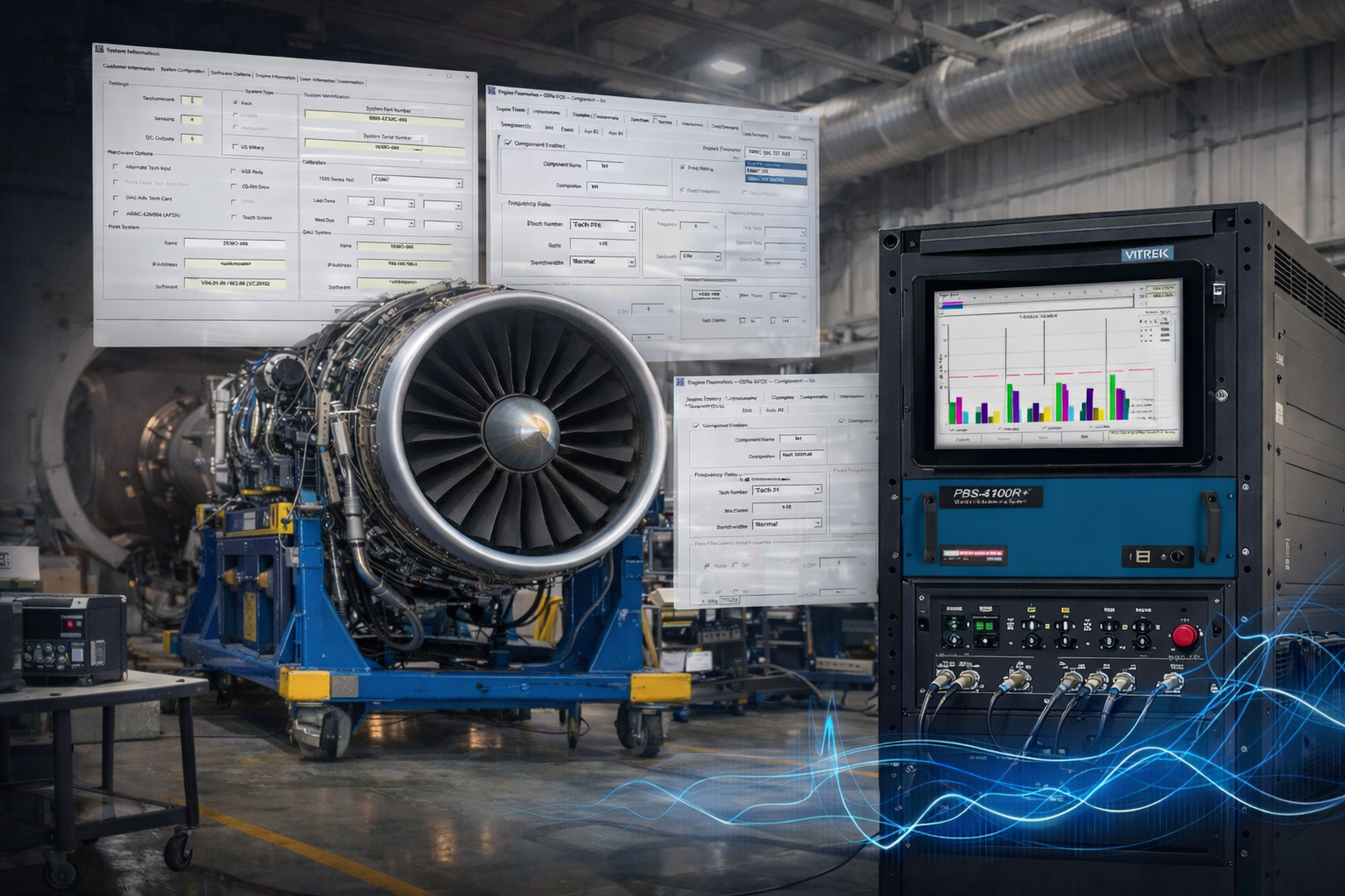
In testing an engine, the operator will execute a vibration survey on the turbine engine. The survey is a slow cycling of engine speed from idle to maximum, then back down to idle again. As this occurs, the PBS-4100 will measure the vibration contribution from each of the spools and chart its findings on a series of plots. In addition, the overall vibration is also plotted.
Should pre-defined limits of vibration be exceeded, the operator is warned. By the conclusion of the vibration survey, the vibration profile is summarized for comparison against the OEM recommendations. If the vibration of any given spool exceeds an allowable limit, it is possible to add off set weights to bring the spool into balance, similar to the addition of lead weights by an auto mechanic onto an imbalanced tire.
Because the vibration magnitude and the angular position are known on the spool, a solution may be calculated with a variety of techniques using the highly-evolved algorithms within the PBS-4100. Such a solution would add one ore more precisely defined weights onto designated locations/angular positions on the spool.

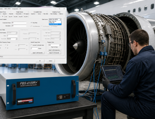
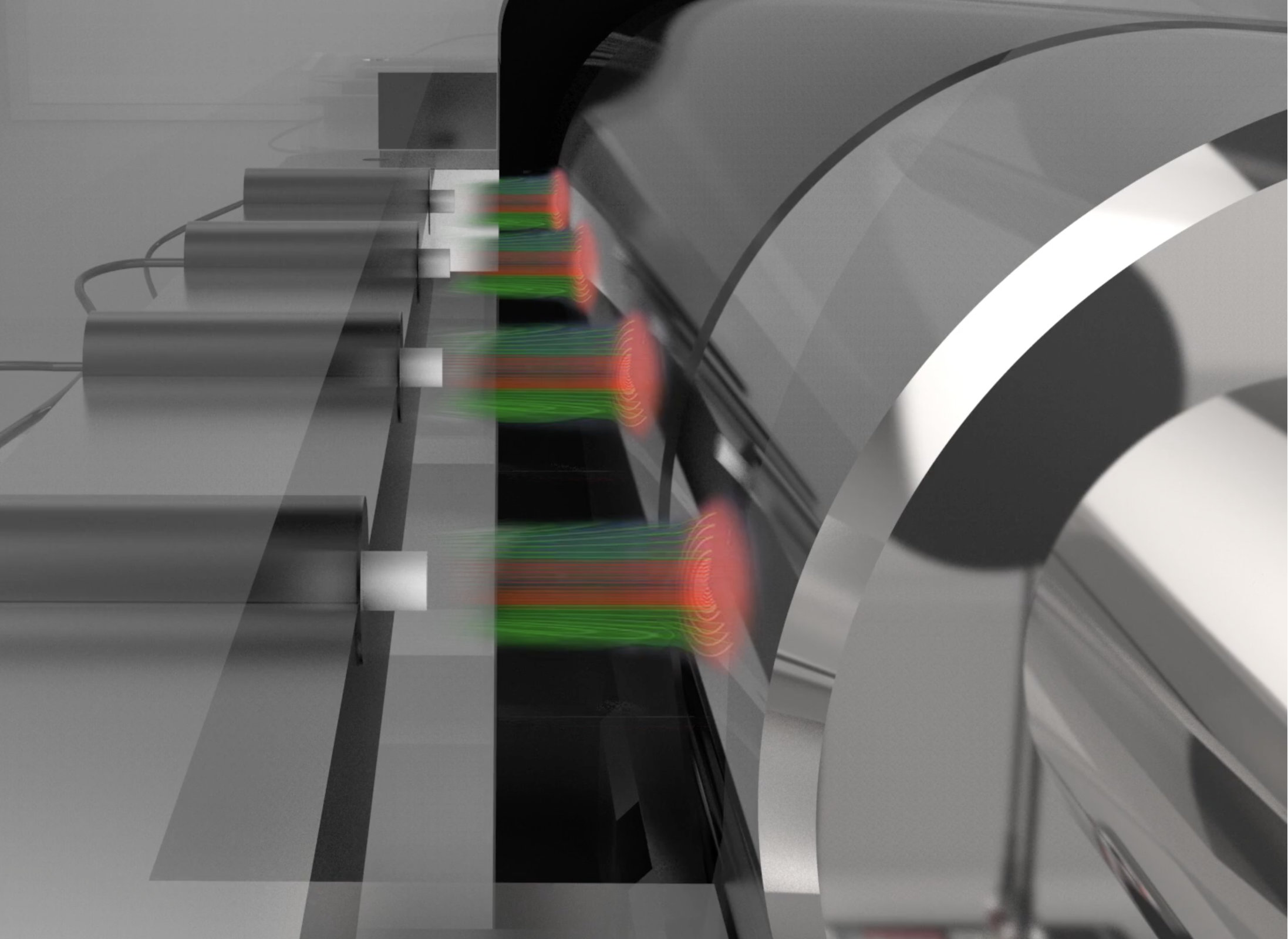
Figure 3. For the technician to understand where to place the balance weights on an engine, the vibration/balancing system must know the engine speed and the phase of vibration.
Recommended Product: MTI Instruments PBS-4100 Series
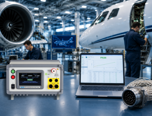
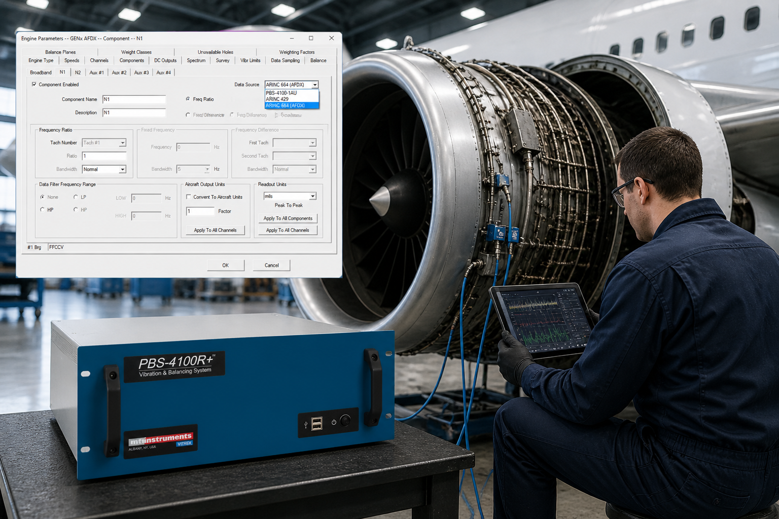
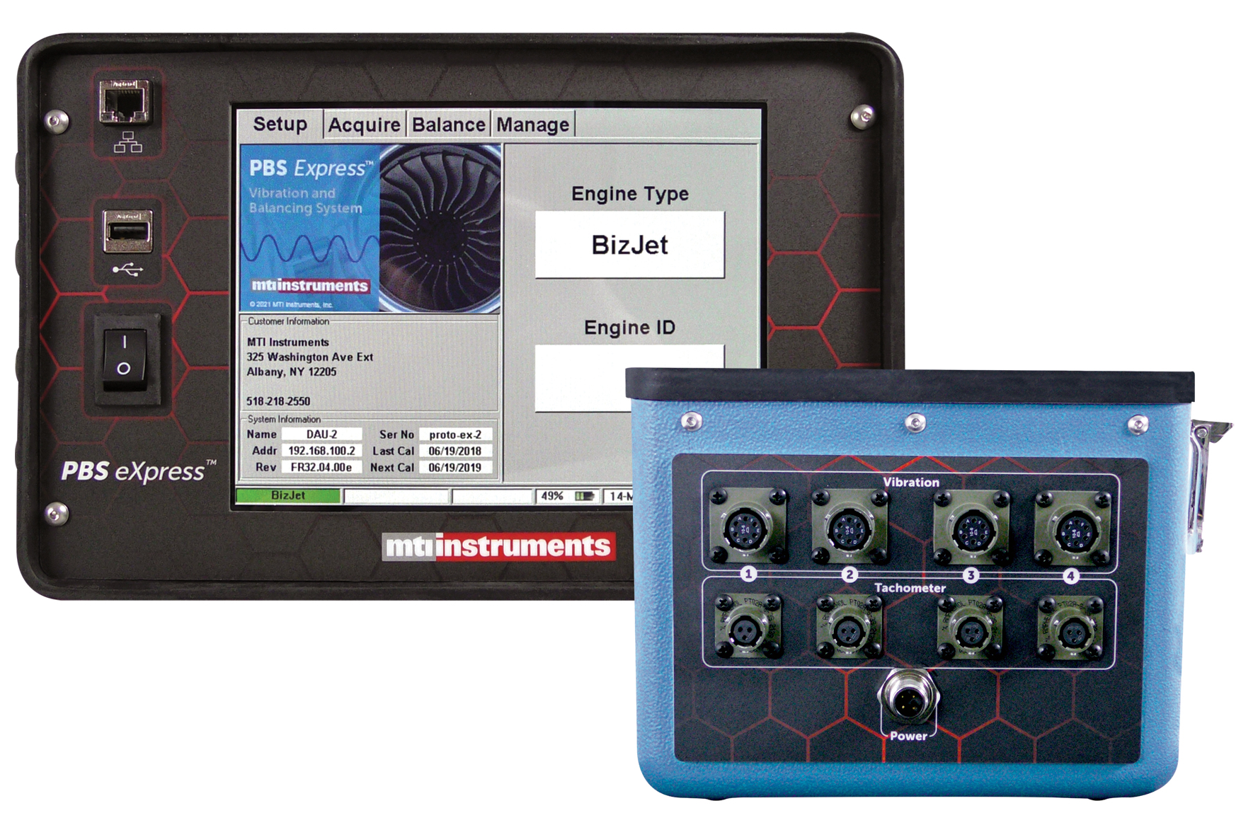
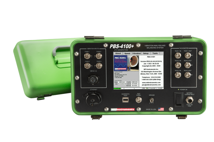
MTI Instruments offers the PBS-4100 series of Engine Vibration/Balancing System. Available in two configurations, the PBS-4100+ is a lightweight, portable system ideal for use on the ground for installed engines (See Figure 2). The test cell version, PBS-4100R+ (Figure 1) is designed for use in a production or
overhaul facility. The principle of operation is identical for both systems and offers an easy-to-use solution that is quick to configure for your specific application.
Both systems off er a simple user interface that asks the user to identify the engine type and any traceability information (ID number, etc.) the balancing system then retrieves operating characteristics and the setup of the engine and provides guidance to the operator to execute an engine vibration survey. Subsequently the reports are furnished to the operator, together with a balance solution, as needed.
Two: A Modern Signal Conditioner for All Engine Types
For some aircraft engine MRO situations, vibration data and balancing are not necessary; only the tachometer signal conditioning functionality is needed. In such cases, a signal conditioning unit is available that utilizes the same tachometer conditioning technology as typical engine vibration/balancing systems and can accommodate all types of engine speeds.
Users can utilize the signal conditioning unit to test engines with a long- or short-tooth embedded N1 signal; engines with older high-voltage tachometer generators; or engines with the new off set tooth design.
Some conditioners can be configured to condition as many as three individual speed signals. Channels A, B and C can be assigned to a different engine speed signal and each channel can be individually controlled and programmed to condition different types of speed signals. Because many engines have primary and secondary speed signals, models such as MTI Instruments’ TSC-4800A off er multiple input sources for each channel.
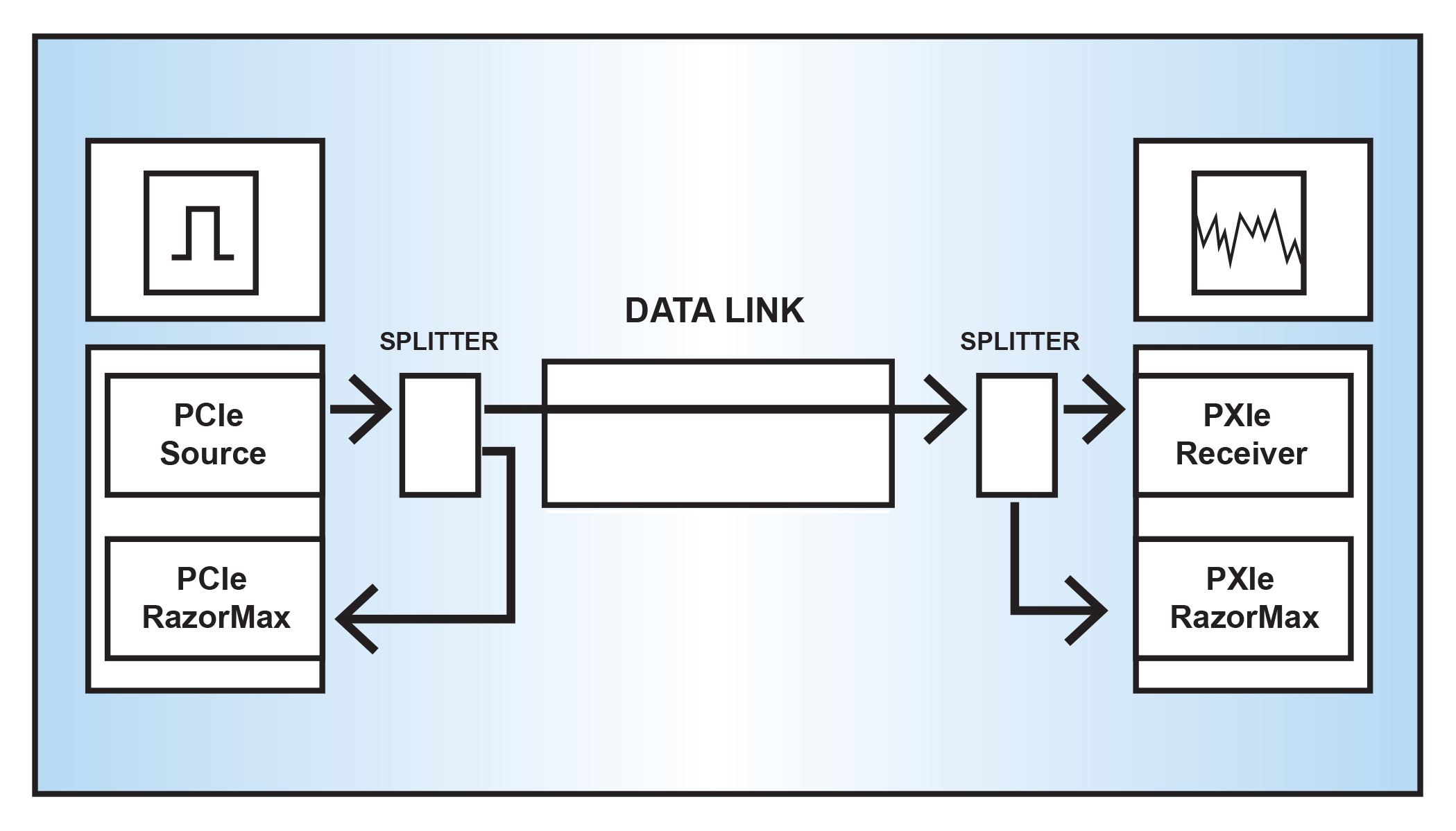
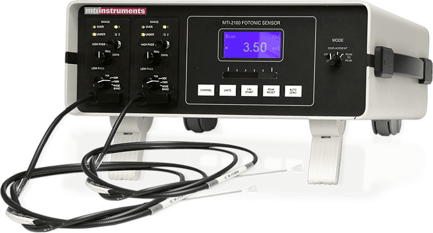
The bottom line: Modern signal conditioners provide useful output signals from all types of inputs. These include pulses coincident with the input signal, pulses coincident with the 1/revolution signal, and raw analog signals proportional to the input signal. Models can also condition signals from engine FADEC systems or other instrumentation. These signals can be square wave signals, triangle waves, and short-duration pulse type signals produced by magnetic sensors – as well as signals from optical and laser sensors.

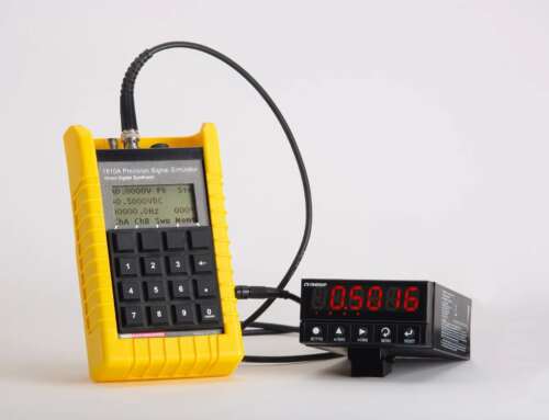
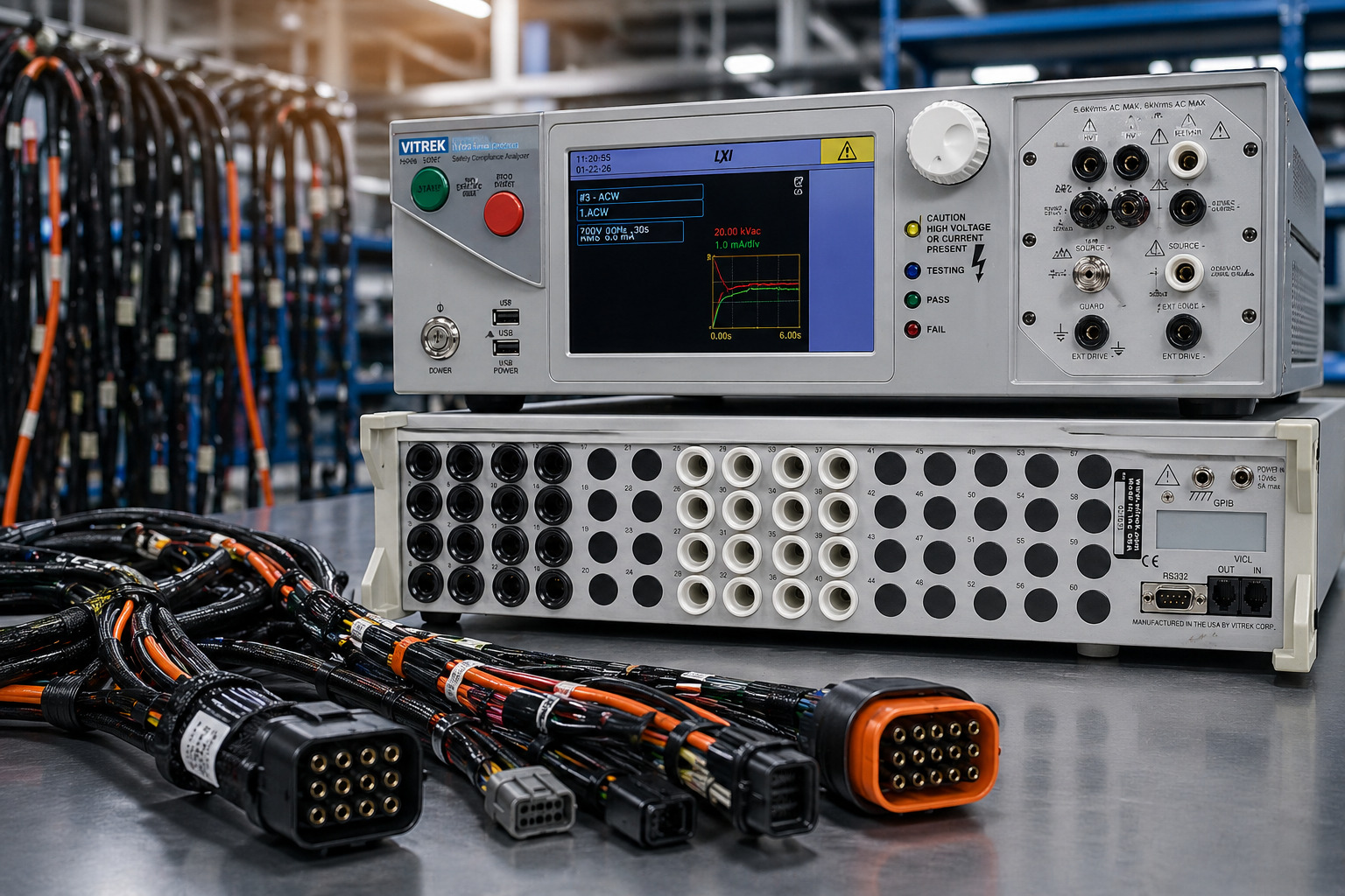
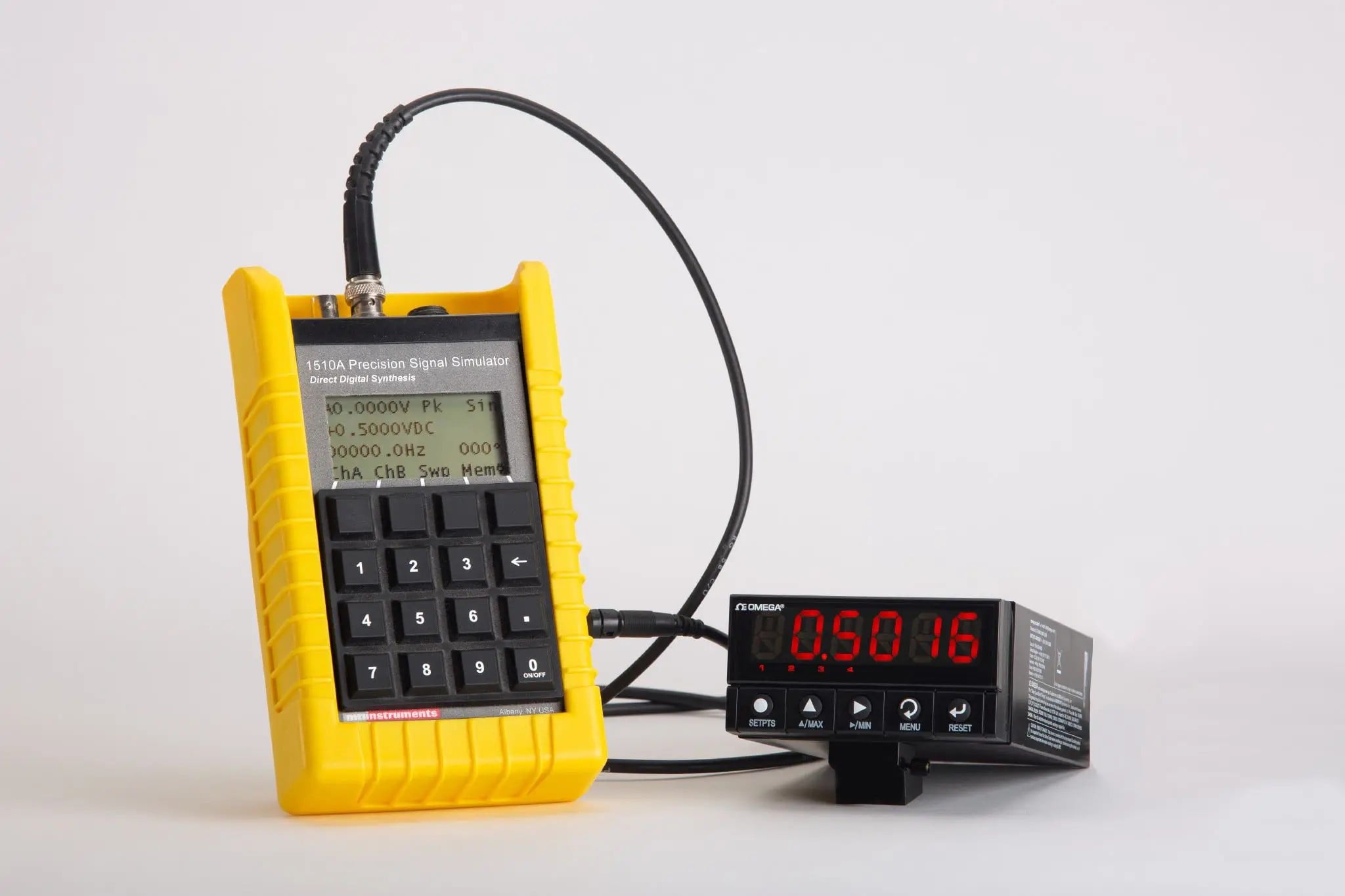
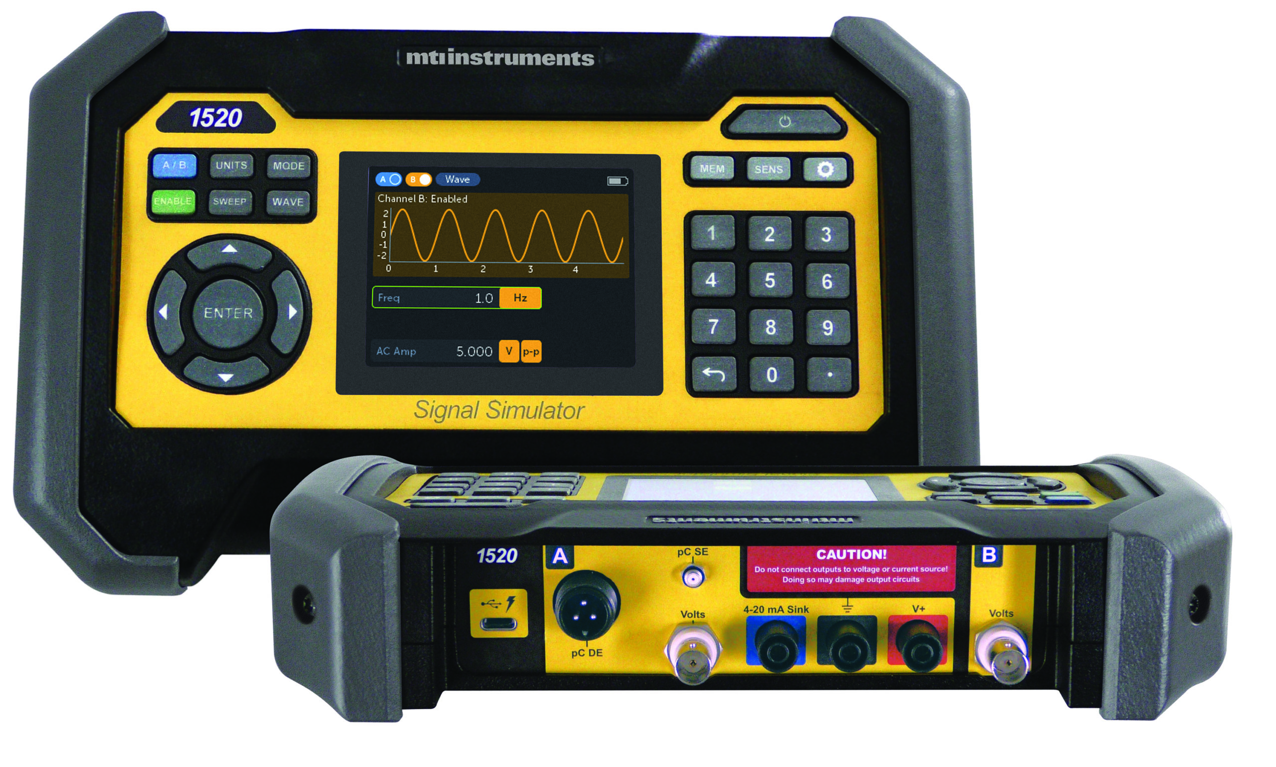
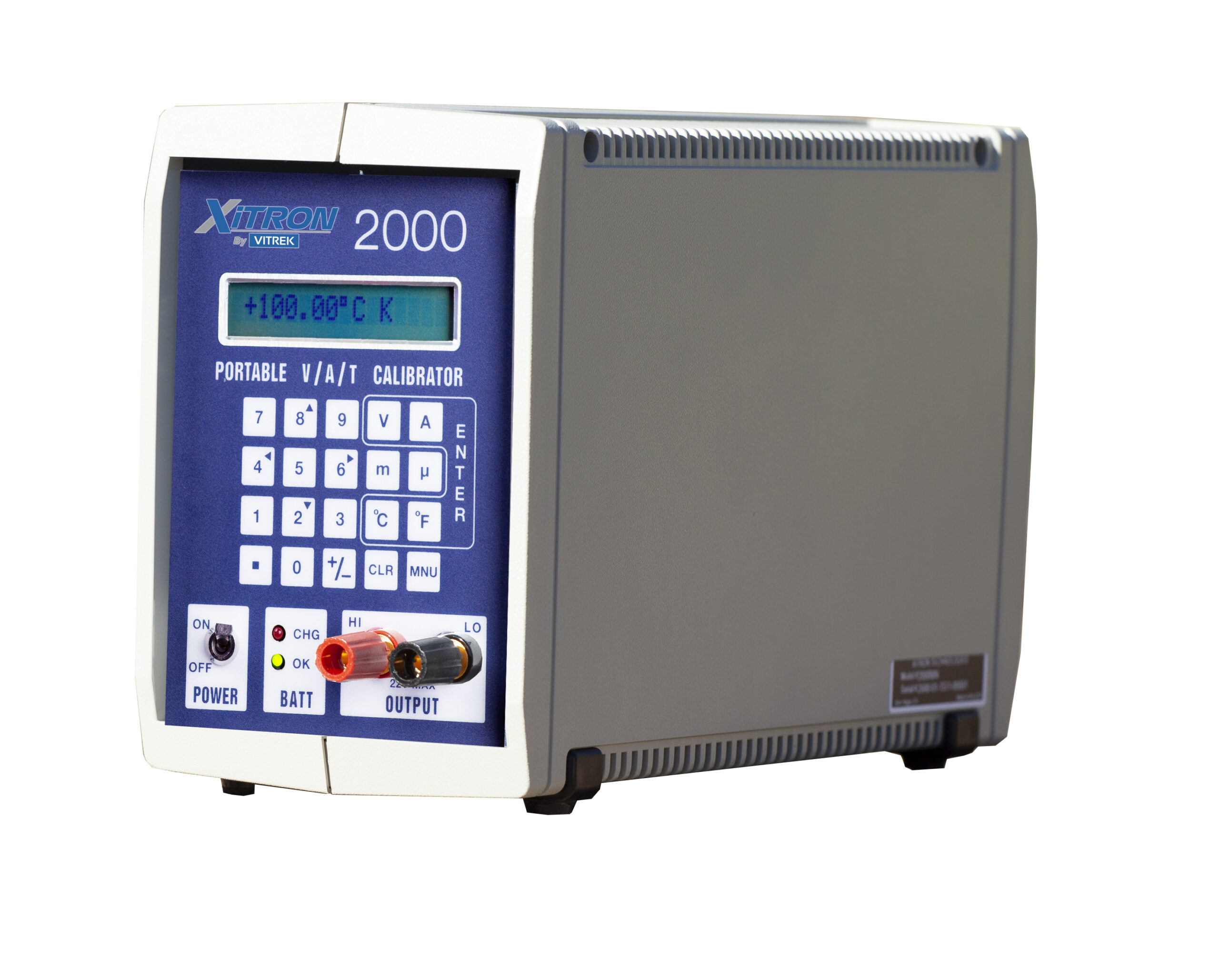
Figure 4. MTI Instruments TSC-4800A Signal Conditioner
How It Works
Each channel of the signal processor typically utilizes a dedicated high-speed signal processor to ensure accuracy and performance. These processors independently sample speed signals 20 million times per second. This means units can reliably detect critical amplitude and timing changes in the speed signal, maintain accurate phasing of the output pulses and track rapid speed changes of the engine.
Advanced units off er full Ethernet control interfaces for configuration, control and testing of the unit. Some incorporate a web style interface which gives users easy access to the unit from any computer running an Internet browser, and can directly control the unit using a simple yet complete machine interface language.
Recommended Product: MTI Instruments TSC-4800A Signal Processor
MTI Instruments off ers the advanced TSC-4800A signal processor (Figure 4) to meet your next tachometer conditioning application. The TSC-4800A is ideal when you only require tachometer signal conditioning without the requirement for vibration and balancing data.
Additional features of the TSC-4800A include enhanced user features including pre-defined conditioner settings that speed up configuration, automatic power-up self test that ensures reliable operation, a firmware based design allowing easy upgrading and an optional Buffered Output card that provides 20 additional
output signals from each input channel.
Three: Innovations in Portable Jet Engine Testing Solutions
Early analysis of turbine vibration can identify problems quickly, saving the time and cost of engine removal. Implementing such troubleshooting techniques, however, can prove difficult. Mechanical constraints under the engine cowls and the complex design of aircraft wiring harnesses can make the installation of accelerometers, charge amplifiers and cables a time consuming and error-prone task.
Portable vibration analysis and engine trim balance instruments connect directly to the engine’s built-in sensors to read necessary signals. Coupled with aircraft-specific accessory kits (AVM Systems), the unit simplifies balancing and vibration testing on almost any jet engine.
Portable units such as MTI Instruments’ PBS 4100+ (Figure 2), as with larger test cell versions, employ a series of on-board digitizers and configurable tracking filters. With these, the operator executes a vibration survey on the turbine engine. The survey is a slow cycling of engine speed from idle to maximum, then back down to idle again. As this occurs, the unit measures the vibration contribution from each spool and plots its findings. In addition, overall vibration is also plotted.
Advanced AVM System Configuration
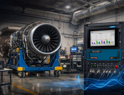
 Figure 5. Advanced systems such as MTI’s PBS-4100 swiftly pinpoint engine problems and eliminates avoidable engine removals. Cable sets and connection accessories are available for all engine and aircraft types.
Conclusion
Today’s advanced technology streamlines testing procedures during- and after- the production processes. Today’s systems are quick to configure and easy to use and are compatible with engines from all major manufacturers including GE, Pratt & Whitney, Rolls-Royce and Honeywell. Solutions from providers like MTI Instruments provides the aviation industry with advanced, easy to use solutions to ensure the quality, safety and reliability of today’s jet engines.
Aviation Engine Vibration Testing Q&A
The Importance of Aviation Engine Vibration Testing
Jet engine vibration is perhaps the worst enemy of an aircraft maintenance team. Out-of-balance parts can lead to cracked fan, turbine and compressor components; general metal fatigue; and if unchecked, catastrophic engine failure. Overall vibration, however, is actually the summation of vibration contributions from any combination of moving parts within the engine, which makes analysis and balancing extremely complicated. Structural characteristics of individual aircraft compound the problem. Engine location on the airframe or type of engine mount, for example, can transmit or magnify vibration troubles. Let’s take a look at some of the industry-wide challenges to aviation safety and service.
What Causes Engine Vibration?
The primary cause of engine vibration is imbalance. Rotating components with an asymmetrical mass distribution impose uneven centrifugal forces which result in vibration. Testing may determine that most of the vibration content is due to rotor imbalance, worn parts (for example, a pump or bearing), or some combination of the two. Vibration & Balancing test systems are used for two main tasks — to check vibration levels and to balance rotors.
How Does an Aircraft Engine Become Unbalanced in the First Place?
The causes for out-of-balance conditions vary widely. Imbalances can result when rotating engine parts such as fan blades are replaced. Damage from bird strikes or other impacts may cause out-of-balance conditions. Natural wear and corrosion, of course, will also lead to a redistribution of mass over time.
How Should an Aircraft Engine be Tested for Vibration, and How Often?
Engine manufacturers specify a maintenance schedule that must be adhered to for their engines. Additionally, the FAA will on occasion issue directives related to engine safety. Included in these recommendations and mandates are specific testing requirements and allowable vibration limits. Some airlines or other aircraft owners may require a stricter schedule and tougher limits than the engine manufacturer. In general, the engine should be tested when the schedule requires, when an impact event occurs, or with any increase in the overall vibration level.
Who is Responsible for Performing Routine Engine Vibration Analysis & Balancing?
Ultimately the aircraft operator is responsible for ensuring the entire aircraft is safe and meets standards. But commercial airlines tend to use one of several options as it relates to engine maintenance. An airline might have its own in-house maintenance crew that’s responsible for the maintenance of the fleet’s aircraft and its engines. It may also use maintenance through the engine’s OEM as part of a maintenance contract, or contract a third-party maintenance crew to manage and conduct a fleet’s maintenance needs. These MRO (Maintenance, Repair and Overhaul) providers — companies such as Lufthansa Technik, HAECO and Delta Tech Ops — may specialize in specific maintenance operations such as engine vibration analysis and balancing. The Military has their own crews to conduct maintenance and repair operations, but they too will leverage contracted services that provide resources, equipment and expertise.
What Role Does Vibration Analysis & Balancing Play In An Engine Lifecycle Management Plan?
All turbine engines have OEM-specified vibration limits, and all airframe and engine manufacturers provide procedures for addressing an out-of-specification vibration condition. These procedures vary in effectiveness, depending on the test equipment specified and/or the skill level of available personnel. With the right tooling and training, these procedures can be used on an emergent basis to bring an engine within limits and save the need for an engine change.
It’s important to note that dramatic cost savings are possible with the latest vibration analysis and trim balance procedures. Traditional methods of fan-only balancing such as the “three shot plot” method, for example, require a minimum of four engine runs to complete.
The industry’s newest precision balancing systems, in comparison, can lower vibration to the minimum possible in one run with consistent, well documented and accurate results. In addition, significant savings can be realized through early analysis of turbine vibration. An advanced portable system can eliminate the need for engine removal and replacement.


