Vitrek White Papers
 Whitepaper: The Future of Cable Testing: Why Intelligent Automation is Replacing Manual Validation Gallery
Whitepaper: The Future of Cable Testing: Why Intelligent Automation is Replacing Manual Validation
Brand-Vitrek, Industry-Aerospace, Industry-Automotive, Industry-Cable Test, Industry-Compliance Testing, Industry-Consumer Products, Industry-Electronics, Industry-Government/Military, Industry-Lighting, Industry-Manufacturing, Industry-Medical, New & Press Releases, Whitepapers-Vitrek
 Automating Complex Cable Testing with the Vitrek V10X and 964i Gallery
Automating Complex Cable Testing with the Vitrek V10X and 964i
Application Notes-Vitrek, Brand-Vitrek, Industry-Aerospace, Industry-Automotive, Industry-Cable Test, Industry-Compliance Testing, Industry-Consumer Products, Industry-Electronics, Industry-Government/Military, Industry-Lighting, Industry-Manufacturing, Industry-Medical, Whitepapers-Vitrek


 Application Note: Replace Three Legacy Systems with One: Modernizing Aerospace/Defense Test Cells with PBS eXpress Gallery
Application Note: Replace Three Legacy Systems with One: Modernizing Aerospace/Defense Test Cells with PBS eXpress
Application Notes-MTI, Brand-MTI, Industry-Aerospace, New & Press Releases, News-Industry, News-MTI, Whitepapers-MTI
 Application Note: Accessing Digital Engine Data for Multi-Platform Aircraft Balancing with MTI PBS Systems Gallery
Application Note: Accessing Digital Engine Data for Multi-Platform Aircraft Balancing with MTI PBS Systems
Application Notes-MTI, Brand-MTI, Industry-Aerospace, New & Press Releases, News-Industry, News-MTI, Whitepapers-MTI
 Choosing the Right Hipot Platform for Modern Manufacturing Electrical Safety Testing Gallery
Choosing the Right Hipot Platform for Modern Manufacturing Electrical Safety Testing
Articles-Vitrek, Industry-Automotive, Industry-Battery, Industry-Cable Test, Industry-Compliance Testing, Industry-Consumer Products, Industry-Electronics, Industry-Government/Military, Industry-Lighting, Industry-Manufacturing, Industry-Medical, Industry-R&D, Knowledge Center-Vitrek, New & Press Releases, Whitepapers-Vitrek

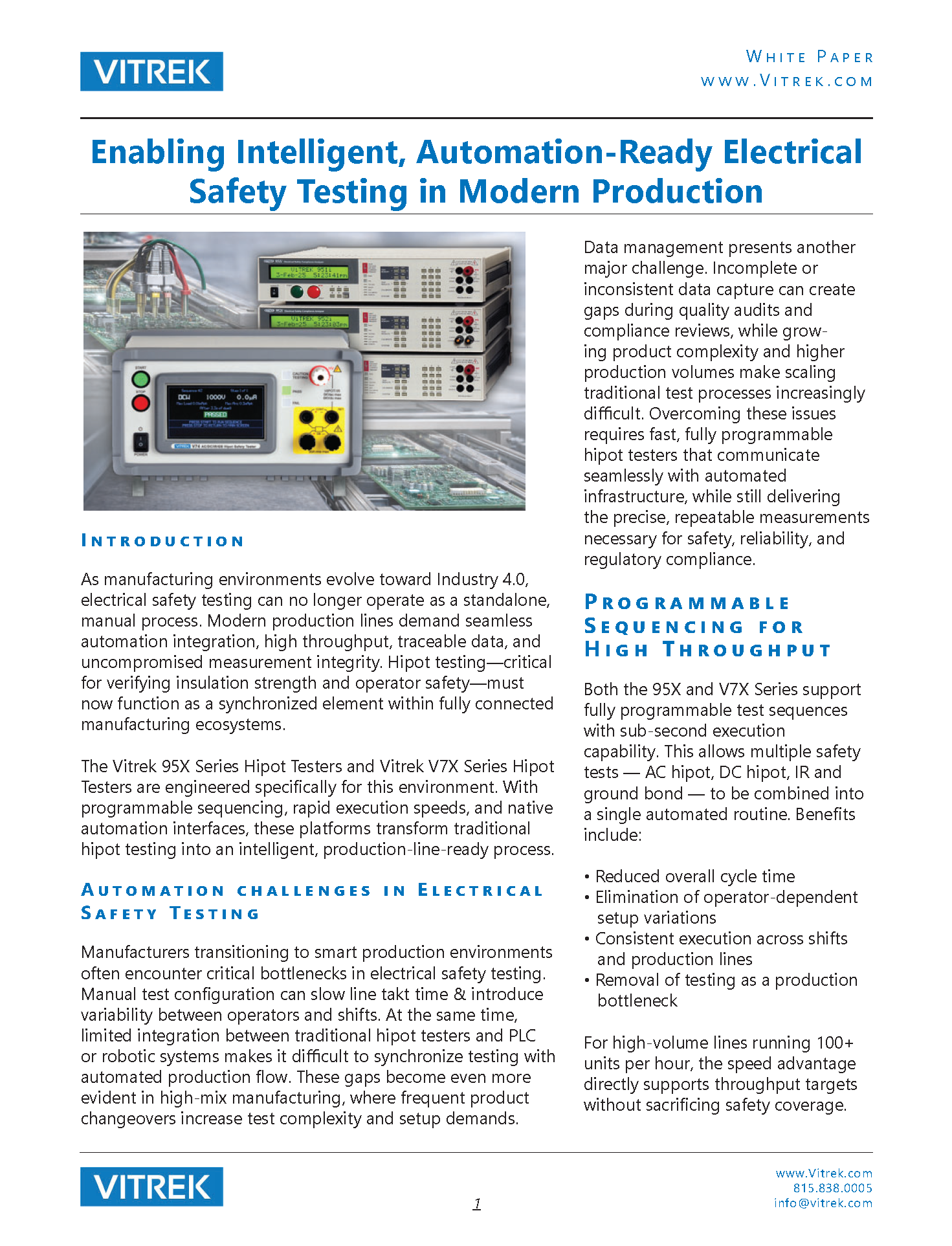 Enabling Intelligent, Automation-Ready Electrical Safety Testing in Modern Production Gallery
Enabling Intelligent, Automation-Ready Electrical Safety Testing in Modern Production
Application Notes-Vitrek, Brand-Vitrek, Industry-Compliance Testing, Industry-Electronics, Industry-Manufacturing, Industry-Measurement Applications, Whitepapers-Vitrek
 Testing Energy-Efficient Washing Machines with the PA900 Power Analyzer Gallery
Testing Energy-Efficient Washing Machines with the PA900 Power Analyzer
Application Notes-Vitrek, Brand-Vitrek, Industry-Compliance Testing, Industry-Electronics, Industry-Manufacturing, Industry-Measurement Applications, Whitepapers-Vitrek
 Ultra-Low Standby Power Testing Made Simple with Vitrek Power Analyzers and EN50564:2011 Gallery
Ultra-Low Standby Power Testing Made Simple with Vitrek Power Analyzers and EN50564:2011
Application Notes-Vitrek, Brand-Vitrek, Industry-Compliance Testing, Industry-Electronics, Industry-Manufacturing, Industry-Measurement Applications, Whitepapers-Vitrek
 Power Analyzers: The Backbone of Modern Electrical Engineering Gallery
Power Analyzers: The Backbone of Modern Electrical Engineering
Brand-Vitrek, Industry-Automotive, Industry-Compliance Testing, Industry-Consumer Products, Industry-Energy, Industry-Manufacturing, Industry-Medical, Industry-Medical, Industry-OEM, Industry-R&D, Industry-Semiconductor, News-All Brands, Products-Vitrek-Power-Analyzer, Whitepapers-Vitrek

 Application Note: Maximizing High-Voltage Measurement Accuracy with the Vitrek 4700 Gallery
Application Note: Maximizing High-Voltage Measurement Accuracy with the Vitrek 4700
Brand-Vitrek, Industry-Cable Test, Industry-Compliance Testing, Industry-Manufacturing, Products-Vitrek-4700, Whitepapers-Vitrek, z1


 Whitepaper: Mastering High Voltage: The Importance of Accurate Test Equipment Gallery
Whitepaper: Mastering High Voltage: The Importance of Accurate Test Equipment
Industry-Cable Test, Industry-Compliance Testing, Industry-Consumer Products, Industry-Electronics, Industry-Manufacturing, Industry-Measurement Applications, Knowledge Center-Vitrek, News-Vitrek, Whitepapers-Vitrek

 Did You Know? GaGe RazorMax Express Digitizer/Oscilloscope: An Efficient & Cost-Effective Tool for High-Energy Physics Particle Counting Applications Gallery
Did You Know? GaGe RazorMax Express Digitizer/Oscilloscope: An Efficient & Cost-Effective Tool for High-Energy Physics Particle Counting Applications
Brand-GaGe, Industry-Government/Military, Industry-Measurement Applications, Industry-Medical, Industry-R&D, Industry-Semiconductor, Industry-Semiconductor-GaGe, Knowledge Center-GaGe, Whitepapers-GaGe

 Case-In-Point: MTI Turbine Vibration Analyzer/Balancing System Technology Principles Gallery
Case-In-Point: MTI Turbine Vibration Analyzer/Balancing System Technology Principles
Application Notes-MTI, Articles-MTI, Industry-Aerospace, Industry-Compliance Testing, Industry-Government/Military, Industry: Transportation, Knowledge Center-MTI, News-Industry, News-MTI-PBS, Whitepapers-MTI
 Article: High-Performance Digitizers in Semiconductor Manufacturing Applications Gallery
Article: High-Performance Digitizers in Semiconductor Manufacturing Applications
Application Notes-GaGe, Articles-GaGe, Industry-Compliance Testing, Industry-Semiconductor, Industry-Semiconductor-GaGe, Knowledge Center-GaGe, News-GaGe, News-Industry, Whitepapers-GaGe
 MTI Instruments Whitepaper: Capacitance Guide for Industrial Applications Gallery
MTI Instruments Whitepaper: Capacitance Guide for Industrial Applications
Brand-MTI, Industry-Aerospace, Industry-Automotive, Industry-Battery, Industry-Compliance Testing, Industry-Consumer Products, Industry-Electronics, Industry-Energy, Industry-Government/Military, Industry-Industrial Processing, Industry-Lighting, Industry-Manufacturing, Industry-Measurement Applications, Industry-OEM, Industry-R&D, Industry-Semiconductor, Industry-Semiconductor-MTI, Industry-Sensors, Industry: Transportation, Knowledge Center-MTI, News-MTI, Whitepapers-MTI


 Whitepaper: Why Capacitance? Benefits and Applications of Digital Capacitive Sensors Gallery
Whitepaper: Why Capacitance? Benefits and Applications of Digital Capacitive Sensors
Brand-MTI, Industry-Automotive, Industry-Compliance Testing, Industry-Consumer Products, Industry-Electronics, Industry-Industrial Processing, Industry-Manufacturing, Industry-Measurement Applications, Industry-Semiconductor, Industry-Semiconductor-MTI, Industry-Sensors, Knowledge Center-MTI, News-MTI, News-Vitrek, Whitepapers-MTI

 Whitepaper: Semiconductor Wafer Measurement for Increased Productivity Gallery
Whitepaper: Semiconductor Wafer Measurement for Increased Productivity
Brand-GaGe, Brand-MTI, Brand-Vitrek, Brands-All, Industry-Consumer Products, Industry-Electronics, Industry-Manufacturing, Industry-OEM, Industry-Semiconductor, Industry-Semiconductor-MTI, Knowledge Center-MTI, News-Industry, News-MTI, Whitepapers-MTI


 GaGe Whitepaper: Wide Bandwidth Digitizer Provides Essential Data Processing in an Innovative Real-Time Channel Sounder for 5G Applications Gallery
GaGe Whitepaper: Wide Bandwidth Digitizer Provides Essential Data Processing in an Innovative Real-Time Channel Sounder for 5G Applications
Industry-Aerospace, Industry-Consumer Products, Industry-Electronics, Industry-Government/Military, Whitepapers-GaGe, z1, ZOK

 MTI Whitepaper: Easy Roller Gap Measurement Ensures Calendering Success Gallery
MTI Whitepaper: Easy Roller Gap Measurement Ensures Calendering Success
Brand-MTI, Industry-Consumer Products, Industry-Manufacturing, Industry-Sensors, News-MTI-Instrumentation, Products-MTI-Capacitance, Whitepapers-MTI, z1
 A Comprehensive Guide to Non-Contact Sensors and Their Applications Gallery
A Comprehensive Guide to Non-Contact Sensors and Their Applications
Application Notes-MTI, Articles-MTI, Brand-MTI, Industry-Sensors, News-MTI-Metrology, Products-MTI-Capacitance, Products-MTI-Laser/Fiber Optic, Products-MTI-Semiconductor/Metrology, Whitepapers-MTI, Z-REPUB, z1
 Vitrek’s Automated Testing System Simplifies and Speeds Automotive Cable/Harness Testing Gallery
Vitrek’s Automated Testing System Simplifies and Speeds Automotive Cable/Harness Testing
Application Notes-Vitrek, Brand-Vitrek, Industry-Automotive, Industry-Consumer Products, Industry-Government/Military, Industry: Transportation, Whitepapers, z1
 White Paper: High Performance Test Equipment Assures LED Lighting Products Comply with Industry Standards Gallery
White Paper: High Performance Test Equipment Assures LED Lighting Products Comply with Industry Standards
Brand-Vitrek, Industry-Consumer Products, Industry-Lighting, News-Industry, News-Vitrek, Products-Vitrek, Whitepapers-Vitrek, z1
 Aircraft Vibration Analysis and Measurement Techniques Gallery
Aircraft Vibration Analysis and Measurement Techniques
Brand-MTI, Industry-Aerospace, Industry-Compliance Testing, Industry-Government/Military, Industry-Manufacturing, Industry: Transportation, Knowledge Center-MTI, News-MTI-PBS, Whitepapers-MTI, Z-REPUB, z1


 White Paper: Electrical Safety & Compliance Testing for Appliance & Consumer Product Manufacturers Gallery
White Paper: Electrical Safety & Compliance Testing for Appliance & Consumer Product Manufacturers
Brand-Vitrek, Industry-Compliance Testing, Industry-Consumer Products, Industry-Electronics, Industry-Manufacturing, News-Vitrek, Products-Vitrek, Whitepapers-Vitrek, z1
 White Paper: Cable & Connector Test System Facilitates Multi-Point High Voltage/Current Testing Gallery
White Paper: Cable & Connector Test System Facilitates Multi-Point High Voltage/Current Testing
Brand-Vitrek, Industry-Aerospace, Industry-Automotive, Industry-Cable Test, Industry-Compliance Testing, Industry-Consumer Products, Industry-Government/Military, Industry-Manufacturing, Industry: Transportation, Whitepapers-Vitrek
 White Paper: Precision Power Analyzers Gallery
White Paper: Precision Power Analyzers
Brand-Vitrek, Industry-Compliance Testing, Industry-Consumer Products, Industry-Electronics, Industry-Energy, Industry-Manufacturing, Industry-R&D, News-Product Updates, News-Products, News-Vitrek, Products-Vitrek-Power-Analyzer, Whitepapers-Vitrek, z1
 Measuring Brake Rotor Thickness Variation with Capacitive Sensing Gallery
Measuring Brake Rotor Thickness Variation with Capacitive Sensing
Brand-MTI, Industry-Aerospace, Industry-Automotive, Industry-Consumer Products, Industry-Government/Military, Industry-Manufacturing, Industry: Transportation, Knowledge Center-MTI, Products-MTI-Capacitance, Whitepapers-MTI, Z-REPUB, z1


Articles
- Choosing the Right Hipot Platform for Modern Manufacturing Electrical Safety Testing Gallery
Choosing the Right Hipot Platform for Modern Manufacturing Electrical Safety Testing
Articles-Vitrek, Industry-Automotive, Industry-Battery, Industry-Cable Test, Industry-Compliance Testing, Industry-Consumer Products, Industry-Electronics, Industry-Government/Military, Industry-Lighting, Industry-Manufacturing, Industry-Medical, Industry-R&D, Knowledge Center-Vitrek, New & Press Releases, Whitepapers-Vitrek

- Case-In-Point: MTI Turbine Vibration Analyzer/Balancing System Technology Principles Gallery
Case-In-Point: MTI Turbine Vibration Analyzer/Balancing System Technology Principles
Application Notes-MTI, Articles-MTI, Industry-Aerospace, Industry-Compliance Testing, Industry-Government/Military, Industry: Transportation, Knowledge Center-MTI, News-Industry, News-MTI-PBS, Whitepapers-MTI
- Article: High-Performance Digitizers in Semiconductor Manufacturing Applications Gallery
Article: High-Performance Digitizers in Semiconductor Manufacturing Applications
Application Notes-GaGe, Articles-GaGe, Industry-Compliance Testing, Industry-Semiconductor, Industry-Semiconductor-GaGe, Knowledge Center-GaGe, News-GaGe, News-Industry, Whitepapers-GaGe
 Article: Advanced Test Equipment Enables LED Lighting Manufacturers to Ensure Compliance with Standards-August, 2022-Designing-Electronics.com Gallery
Article: Advanced Test Equipment Enables LED Lighting Manufacturers to Ensure Compliance with Standards-August, 2022-Designing-Electronics.com
Articles-Vitrek, Brand-Vitrek, Industry-Lighting, News-Vitrek, Products-Vitrek, Products-Vitrek-4700, Products-Vitrek-964i, Products-Vitrek-98x, Products-Vitrek-DL Load, Products-Vitrek-Hipot, Products-Vitrek-Power-Analyzer, Products-Vitrek-QT, z1
 Why You Need Automotive Cable Tests Before Cars Hit the Road Gallery
Why You Need Automotive Cable Tests Before Cars Hit the Road
Articles-Vitrek, Blog, Brand-Vitrek, Electrical Safety Testing Blog, Industry-Automotive, Industry-Cable Test, Industry-Compliance Testing, Industry-Government/Military, Industry-Manufacturing, Industry: Transportation, Products-Vitrek-964i, z1

- A Comprehensive Guide to Non-Contact Sensors and Their Applications Gallery
A Comprehensive Guide to Non-Contact Sensors and Their Applications
Application Notes-MTI, Articles-MTI, Brand-MTI, Industry-Sensors, News-MTI-Metrology, Products-MTI-Capacitance, Products-MTI-Laser/Fiber Optic, Products-MTI-Semiconductor/Metrology, Whitepapers-MTI, Z-REPUB, z1


 How Aircraft Operators Reduce Downtime While “Sweating the Assets” Gallery
How Aircraft Operators Reduce Downtime While “Sweating the Assets”
Articles-MTI, Brand-MTI, Industry-Aerospace, Industry-Compliance Testing, Industry-Government/Military, Industry-Manufacturing, Industry: Transportation, News-MTI-PBS, Products-MTI-Engine Balancing, Z-REPUB, z1


Vitrek in the News…

Electrical Safety Testing in Automotive Manufacturing: A Complete Guide for Engineers
A wiring defect that escapes detection during production can become a costly problem once a vehicle enters service. Whether the issue originates in a wire harness, connector, inverter, battery pack, or charging system, the consequences can include warranty claims, production rework, safety concerns, and damage to brand reputation.
Automotive electrical testing helps manufacturers identify these issues. It is the systematic application of electrical safety and verification tests to vehicle components, assemblies, and systems before they are installed in a vehicle or released to customers. The objective is to confirm that electrical circuits perform as intended, insulation systems remain intact, protective ground paths meet safety requirements, and products comply with applicable industry standards.
This post explains what automotive electrical testing involves, the core tests used throughout production, how testing requirements change for electric vehicles, and the standards and technologies manufacturers use to verify electrical safety before products reach the customer.

What Does Automotive Electrical Testing Cover?
Unlike basic functional testing, which verifies whether a component operates correctly, automotive electrical testing focuses on the electrical integrity and safety of the product. It helps identify defects that may not affect immediate operation but could lead to failures under real-world conditions.
The scope of automotive electrical testing spans nearly every electrically active component found in modern vehicles, including
- Wire Harnesses and Cable Assemblies: Wire harnesses are among the most frequently tested automotive components. Most vehicles contain extensive networks of cables connecting control modules, sensors, lighting systems, infotainment units, and powertrain electronics. Testing verifies conductor continuity, insulation integrity, and resistance to the voltages encountered during operation.
- EV Battery Packs and High-Voltage Interconnects: Electric vehicles operate at significantly higher voltages than conventional internal combustion engine vehicles. Battery packs, high-voltage cables, motor connections, and DC-link assemblies require testing to verify insulation integrity, electrical isolation, and overall system safety under high-voltage operating conditions.
- Power Electronics: Components such as inverters, DC-DC converters, and onboard chargers contain both high-voltage and low-voltage circuits. Testing helps verify electrical isolation between circuits and confirms that insulation systems perform as intended during operation.
- Connectors and Terminal Assemblies: Connectors play a critical role in maintaining reliable electrical connections throughout the vehicle. Testing verifies proper conductor routing, contact integrity, insulation between adjacent terminals, and overall assembly quality.
- Charging System Components: Charging interfaces, charging cables, and onboard charging equipment must meet stringent electrical safety requirements. Testing helps confirm insulation performance, grounding integrity, and compliance with applicable charging system standards before installation.
- Electric Motors and Drive Systems: Traction motors and associated drive systems operate under demanding electrical and environmental conditions. Testing helps verify winding insulation integrity, electrical isolation, and the overall safety of high-voltage motor assemblies.
- Electronic Control Units (ECUs): Advanced vehicles may contain dozens of ECUs responsible for managing powertrain, safety, body control, and infotainment functions. Testing helps verify circuit integrity, insulation performance, and proper isolation between electrical systems.
Four Common Automotive Electrical Safety Tests
Automotive electrical safety verification commonly relies on four core tests. Each test evaluates a different aspect of electrical integrity, and together they help identify defects that may affect safety, reliability, or compliance.
1.Continuity Testing: Continuity testing helps verify that conductors within an assembly are present, unbroken, and connected to the intended terminals. The test applies a low voltage and measures the resistance of each conductor path against predefined acceptance limits.
This test is commonly used to identify:
- Open circuits
- Missing connections
- High-resistance joints caused by poor crimps or terminations
- Miswiring and incorrect conductor routing
While continuity testing is essential, it cannot detect insulation weaknesses, leakage paths, or voltage-dependent failures. A harness may pass continuity testing and still contain defects that create safety risks under operating conditions. For this reason, continuity testing is often used alongside additional electrical safety tests to provide broader defect coverage.
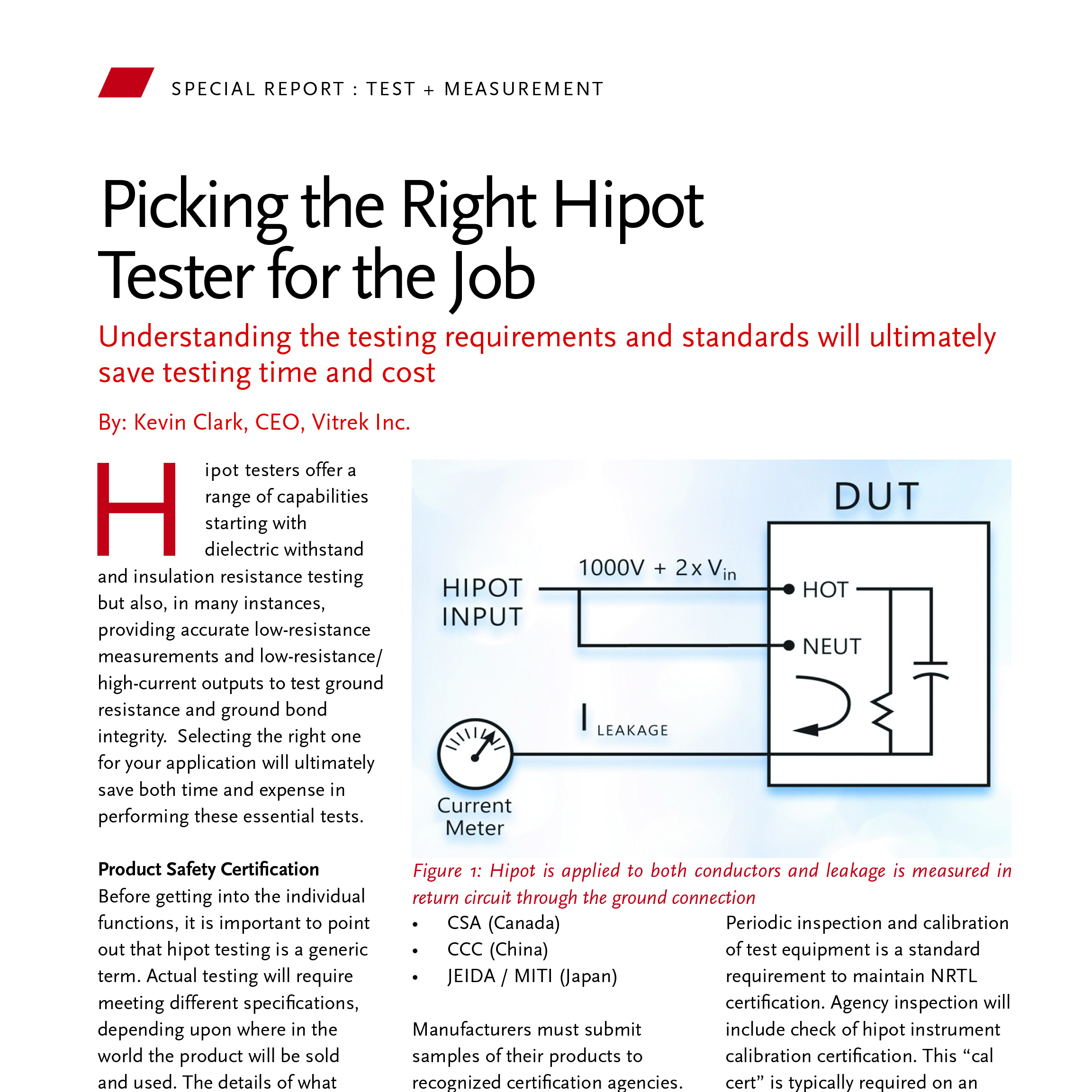
2.Hipot Testing (Dielectric Withstand Testing): Hipot testing evaluates the ability of insulation systems to withstand a specified electrical stress without excessive leakage current or breakdown. The test applies a high voltage between conductors or between conductors and chassis ground while measuring leakage current through the insulation.
Excessive leakage current may indicate insulation breakdown, contamination, insufficient spacing, or other defects that could affect electrical performance in service.
Hipot testing is effective for identifying:
- Insulation breakdown
- Voltage-dependent defects
- Arc-over conditions between adjacent conductors
- Manufacturing defects that may not be visible during inspection
Depending on the application and applicable standard, manufacturers may use either AC or DC hipot testing.
- AC hipot testing applies alternating voltage and is commonly used to evaluate insulation performance under electrical stress.
- DC hipot testing is often used to evaluate resistive leakage paths and potential insulation degradation while minimizing charging current effects in capacitive devices.
Test voltage should be established according to the applicable standard, product specifications, and OEM requirements rather than relying on generalized values.
3.Insulation Resistance Testing: Insulation resistance (IR) testing measures the resistance of insulating materials by applying a DC voltage and evaluating the resulting current flow.
Unlike hipot testing, which focuses on insulation performance under a specified voltage stress, IR testing evaluates the resistance characteristics and overall condition of the insulation system.
Insulation resistance testing is particularly valuable for detecting:
- Moisture contamination
- Surface leakage paths
- Insulation degradation
- Residues from manufacturing processes
In automotive applications, where wiring systems may be exposed to humidity, temperature cycling, vibration, and environmental contaminants, insulation resistance testing can help identify developing insulation issues before they become significant.
A component may successfully pass a hipot test while still exhibiting insulation resistance levels below acceptable limits. As a result, both tests are commonly used together to provide a more complete assessment of insulation integrity.
4.Ground Bond Testing: Ground bond testing evaluates the integrity of protective ground connections by applying a specified test current through the ground path and measuring the resulting resistance.
Ground bond testing helps identify:
- Loose ground connections
- Improper terminations
- Damaged ground conductors
- Excessive resistance in protective earth paths
Test current requirements vary depending on the applicable standard. Standards such as IEC 61010, IEC 60335, and OEM-specific specifications define acceptable resistance limits and test current levels. These requirements should be verified before establishing test procedures.
Automotive Electrical Testing at Each Production Stage
Electrical testing is performed throughout the manufacturing process, from incoming material inspection to final vehicle release. Each stage serves a different purpose, helping manufacturers identify defects early, maintain quality standards, and document compliance throughout production. Check out the key stages below:
1.Component Level: Incoming inspection testing verifies that supplier-provided cables, connectors, terminals, and other electrical components meet specified performance requirements before they are incorporated into assemblies. Detecting defects at this stage helps prevent faulty materials from moving further into the manufacturing process, where replacement costs and production disruptions become significantly higher.
Incoming inspection records also support traceability requirements established under quality management systems such as IATF 16949, creating a documented link between supplied materials and finished vehicles.
2.Sub-Assembly Level: Once assemblies are built, electrical testing helps verify that manufacturing processes have produced a properly functioning and electrically safe product. Continuity, hipot, insulation resistance, and ground bond testing methods help identify wiring errors, insulation defects, contamination, and grounding issues that may not be visible during assembly.
Testing becomes more challenging as harness complexity increases. Comprehensive harness verification may require evaluating many conductor combinations and isolation paths within the assembly. For example:
- A 4-conductor harness requires 20 test combinations.
- A 24-conductor harness requires 578 test combinations.
Performing these sequences manually can slow production and increase the risk of missed connections or incomplete coverage.
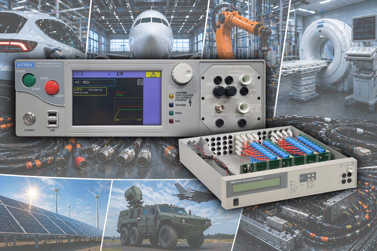
To address this challenge, the Vitrek 964i High Voltage Switching System automates multi-point test sequencing. The system supports up to 999 sequential switching operations with reconnect speeds as fast as 0.025 seconds, helping manufacturers execute comprehensive harness testing while maintaining production throughput.
3.Vehicle Assembly: End-of-line testing provides the final electrical verification before a vehicle leaves the production facility.
At this stage, manufacturers evaluate installed electrical systems, including wire harnesses, power electronics, charging systems, and high-voltage components in electric vehicles. The objective is to confirm that the completed vehicle meets defined electrical safety and performance requirements before delivery.
Equally important is documenting the results. Test records provide evidence that required inspections were completed and support quality audits, compliance programs, and production traceability.
Vitrek’s QT Insite software supports automated test management through features such as barcode-driven test profile selection, per-unit result logging, and exportable reporting formats including PDF and CSV files. These capabilities help manufacturers maintain consistent documentation and support IATF 16949 traceability requirements.
4.Field and Service Testing: Electrical testing remains important after production. Components that have been repaired, replaced, or serviced should be verified before returning to operation. Post-repair testing helps verify that electrical integrity, insulation performance, and grounding paths continue to meet applicable specifications or service requirements.
EV-Specific Automotive Electrical Testing Requirements
Vehicle electrification has introduced new testing challenges that extend well beyond those found in conventional 12V and 48V vehicle systems. Higher operating voltages, additional safety mechanisms, and evolving regulatory requirements have expanded the scope of automotive electrical testing for EV manufacturers and suppliers.
-
Higher Voltage Requirements: The shift from conventional 12V and 48V vehicle systems to EV architectures operating at 400V and 800V has significantly expanded electrical testing requirements. Battery packs, high-voltage cables, inverters, motor drives, and charging systems require insulation verification at voltage levels substantially higher than those used in traditional automotive applications.
As a result, manufacturers often require hipot and insulation resistance test equipment capable of evaluating insulation performance under the conditions specified by applicable standards and OEM requirements. The Vitrek V10X Series supports DC hipot testing up to 15 kV DC, making it well suited for high-voltage EV component testing where conventional automotive test equipment may not provide sufficient voltage capability.
-
New Testing Requirements: EV platforms introduce additional safety systems that require verification during production and validation testing.
- High-Voltage Interlock Loop (HVIL) Verification: The high-voltage interlock loop is a safety circuit designed to disconnect or disable high-voltage power whenever a connector or enclosure is opened. Testing helps verify that the interlock circuit remains intact and responds correctly when a connector separation or access event occurs. This safety mechanism is commonly used in high-voltage vehicle architectures and has no direct equivalent in most conventional ICE vehicle systems.
- Insulation Monitoring System Verification: Many EVs incorporate insulation monitoring systems that continuously monitor insulation health during operation. Verification testing helps confirm that these systems can detect and report insulation faults before they create a potential safety concern.
- Charging System Testing: EV charging systems introduce additional testing requirements for on-board chargers, charging interfaces, and associated high-voltage connections. These systems must be evaluated for insulation performance, grounding integrity, and compliance with applicable charging standards such as IEC 61851.
-
EV Electrical Testing Standards: EV electrical testing is governed by a combination of vehicle safety, battery, charging, and functional safety standards. Common referenced standards include:
- ISO 6469: Covers safety requirements for electric road vehicles, including protection against electrical hazards associated with high-voltage systems.
- IEC 62660: Defines performance and testing requirements for lithium-ion cells used in electric vehicle propulsion applications.
- UNECE R100: Establishes type-approval requirements for electric powertrain vehicles, including high-voltage electrical safety provisions.
- ISO 26262: Defines functional safety requirements for automotive electrical and electronic systems and may influence the development and validation of safety-related EV functions.
- IEC 61851: Covers conductive charging system requirements for electric vehicles.
One important consideration is that EV hipot test voltages are application-specific rather than universal. Required test voltages vary based on component type, system architecture, operating voltage, and customer specifications. Test parameters should therefore be established according to applicable standards, OEM requirements, and product specifications rather than predetermined assumptions.
Automotive Electrical Testing Standards
While EV-specific standards address high-voltage safety, battery systems, and charging infrastructure, manufacturers must also comply with broader automotive quality and component testing standards that apply across vehicle platforms.
Automotive electrical testing programs are guided by a range of industry standards that define performance, safety, quality, and documentation requirements for vehicle components and assemblies. Some of the most commonly referenced standards include:
- IATF 16949: Defines automotive quality management requirements, including traceability, process control, corrective action procedures, and test documentation.
- LV 112: Establishes performance and testing requirements for high-voltage automotive cables and conductors used in electrified vehicle applications.
- ISO 19642: Specifies performance, construction, and testing requirements for road vehicle cables.
- USCAR-2: Defines performance and validation requirements for automotive electrical connector systems.
- LV 124: Covers electrical, environmental, and durability testing requirements for electrical and electronic components used in 12V and 48V vehicle electrical systems.
These standards help manufacturers establish consistent test procedures, verify product quality, and demonstrate compliance throughout the production process.
Vitrek Automotive Electrical Testing Platform
Vitrek offers an electrical safety testing platform that supports automotive manufacturers across multiple stages of the production process, including component validation, assembly testing, end-of-line verification, and traceability management.
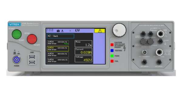
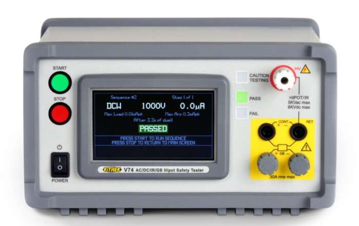
- V7X Series Hipot Testers: The V7X Series provides compact electrical safety testing for automotive components and assemblies. These systems are well suited for testing 12V and 48V vehicle components where production environments require reliable hipot testing in a smaller footprint.
- 95X Series Hipot Testers: High-capacitance automotive wire harnesses can present challenges for conventional hipot testers. The 95X Series addresses this with 500VA output power, helping maintain the specified test voltage when evaluating large harness assemblies and other capacitive loads.
- 964i High Voltage Switching System: As wire harness complexity increases, manufacturers may need to evaluate many conductor combinations and isolation paths. The 964i automates multi-point switching with support for up to 999 sequential test connections and reconnect speeds as fast as 0.025 seconds. Multiple relay card options support a wide range of hipot, insulation resistance, and ground bond testing requirements within a single automated test sequence.
- QT Insite Software: QT Insite provides centralized test automation, data collection, and traceability management. Features such as barcode-driven test sequence selection, per-unit result logging, database storage, and PDF or CSV reporting can help manufacturers maintain consistent documentation and support IATF 16949 traceability and quality management requirements.
- V10X Series Hipot Testers: For EV battery systems, high-voltage cables, power electronics, and charging components, the V10X Series provides expanded test capability with AC hipot up to 10 kV standard, optional AC testing up to 30 kV, and DC hipot testing up to 15 kV. These capabilities make the system well suited for applications that require higher test voltages to evaluate insulation performance in EV and other high-voltage electrical systems.
Common Mistakes to Avoid in Automotive Electrical Testing
Even well-designed test programs can be affected by avoidable errors that impact product quality, traceability, and overall testing effectiveness.
- Relying on Continuity Testing Alone: Continuity testing verifies conductor routing and connectivity; it does not evaluate insulation quality. A harness may pass continuity testing while still containing insulation defects that only become apparent during hipot or insulation resistance testing.
- Using Insufficient Test Voltage for EV Components: High-voltage EV systems require test voltages appropriate for the component, operating voltage, and applicable standard. If the test voltage is too low, insulation performance may not be adequately evaluated under expected operating conditions.
- Maintaining Paper-Based Test Records: Manual recordkeeping can make traceability, data retrieval, and audit preparation more difficult. Automated electronic documentation can help improve consistency while supporting quality management and compliance requirements.
- Applying Incorrect Test Parameters: Different standards and OEM specifications may require different voltage levels, test currents, and acceptance criteria. Test parameters should be verified against applicable standards, product specifications, and customer requirements before testing begins.
Build a More Reliable Automotive Test Program with Vitrek
Identifying electrical defects during production can help reduce the costs and operational challenges associated with post-production repairs, warranty claims, and field failures. Establishing an effective electrical test program that incorporates continuity, hipot, insulation resistance, ground bond testing, and automated data management can help manufacturers improve product quality, support compliance efforts, and strengthen traceability throughout the production process.
Vitrek offers a range of automotive electrical testing solutions to support these requirements, including high-power hipot testing, automated multi-point switching, EV high-voltage component verification, and traceability-focused test management tools. Explore the 95X Series Hipot Testers, 964i High Voltage Switching System, V10X Series Hipot Testers, and QT Insite Software to learn more about the available testing capabilities. Contact Vitrek to discuss your testing requirements and evaluate solutions that align with your production, quality, and compliance objectives.

How Accurate Should Power Analyzers Be?
A 0.1% error in voltage rarely stays a 0.1% error by the time you calculate true power, efficiency, or standby consumption. Once voltage, current, phase angle, bandwidth, and harmonic content all enter the measurement chain, small instrument errors can stack into a large decision error. That is why asking how accurate should power analyzers be is not a matter of picking the tightest spec on a datasheet. It is a matter of matching measurement uncertainty to the engineering risk, compliance requirement, and operating conditions of the test.
How accurate should power analyzers be for real applications?
The short answer is that a power analyzer should be accurate enough that the instrument does not materially affect the pass-fail decision, design conclusion, or efficiency claim. In practice, that threshold changes by application.
If you are checking broad production trends on a stable line, moderate accuracy may be enough. If you are validating inverter efficiency, comparing motor drive topologies, measuring very low power factor loads, or documenting compliance to a regulatory limit, the analyzer needs significantly tighter performance. In those cases, the question is less about the headline percentage and more about total measurement uncertainty across the actual test conditions.
A common mistake is to specify accuracy in isolation, such as demanding 0.01% basic power accuracy without asking whether the test setup, transducers, lead routing, thermal drift, and signal content support that level of performance. Another common mistake is the opposite one: selecting a general-purpose meter with nominal watt measurements for work that depends on phase accuracy, crest factor handling, and harmonic fidelity.
For most engineering teams, the right answer starts with this principle: instrument uncertainty should be comfortably smaller than the tolerance band or performance difference you need to detect. If your efficiency target differs by 0.2%, an analyzer uncertainty near that same level is not good enough. If your standby power limit is measured in fractions of a watt, low-level resolution and phase performance become central, not optional.
Accuracy is more than one number
A datasheet often leads with a single basic accuracy value, but that figure can be misleading if it is read without context. Power analyzer performance is usually shaped by several interacting terms: voltage accuracy, current accuracy, phase accuracy, power calculation accuracy, range dependence, frequency response, temperature coefficient, and time stability.
That matters because true power is derived, not directly sensed in isolation. Real power depends on simultaneous voltage and current sampling and the precise calculation of the phase relationship between them. When waveforms are distorted or the power factor is low, errors that look minor on paper can become significant in use.
For example, measuring a nearly resistive heater at line frequency is a very different task from measuring a PWM motor drive, a high-frequency converter, or a low-power standby load with non-sinusoidal current draw. In the first case, a broader class of analyzers may perform adequately. In the latter cases, bandwidth, sampling architecture, and phase integrity often matter as much as nominal base accuracy.
This is why experienced users look past a single specification and evaluate the uncertainty model over the ranges and waveform conditions they actually expect to test.
Why phase accuracy changes the answer
Phase error is one of the fastest ways to corrupt a power reading, especially at low power factor. Even a small angular error can create a disproportionate wattage error when current lags or leads voltage significantly. That makes phase performance critical in motor drives, transformers, inductive loads, and many power electronics systems.
If your work involves distorted waveforms or switching devices, harmonic phase behavior also matters. The analyzer must preserve timing fidelity across the relevant frequency content, not just at 50 or 60 Hz. Otherwise, the computed power components may look stable while still being wrong.
Why range and loading matter
Power analyzers are never equally accurate on every range. The same instrument that performs well near the center of a range may degrade near the bottom end, where offset and noise become more influential, or near the top end, where thermal effects and overload margin come into play.
That is especially important for products with wide operating envelopes, such as EV subsystems, variable-speed drives, appliances with standby and peak modes, and aerospace power systems. If one analyzer must cover microamp-level standby current and high-load transients, the range architecture and current sensing approach deserve close attention.
A practical way to decide how accurate power analyzers should be
Start with the decision you need the data to support. Are you comparing design iterations, qualifying to a specification, documenting compliance, or controlling a production process? The tighter the decision threshold, the tighter the analyzer uncertainty must be relative to that threshold.
Next, define the full operating window. Include voltage, current, frequency, waveform shape, crest factor, power factor, and ambient conditions. Accuracy claims only matter if they hold under your real signal conditions.
Then build an uncertainty budget. This should include the analyzer itself, any external current shunts or transducers, wiring effects, fixture repeatability, environmental drift, and calibration status. In many labs, the analyzer is only one part of the total uncertainty.
A useful engineering rule is to keep total measurement uncertainty meaningfully below the limit or difference you care about. There is no universal ratio, but many teams want at least a 4:1 margin between the tolerance band and the uncertainty of the measurement system. If your margin is tighter than that, the data may still be usable, but decision confidence drops and disputes become more likely.
Application-specific expectations
R&D efficiency work usually demands higher analyzer performance than routine go-no-go production checks. When engineers are trying to quantify whether a topology change improved conversion efficiency by a few tenths of a percent, they need low uncertainty, stable phase measurement, and repeatable results across ranges and test days.
Compliance testing can be even less forgiving. Standards-based work often requires traceability, documented calibration, and confidence that the instrument behavior aligns with the method prescribed for the test. If a regulation sets a narrow limit on standby power, harmonics, or energy consumption, the analyzer should not consume most of the allowable error budget.
Production environments are different. Speed, ruggedness, and repeatability may matter as much as absolute best-case accuracy. But even here, under-specifying the analyzer can create hidden cost through false failures, false passes, and poor correlation with validation lab data.
In power electronics, EV, aerospace, and defense applications, waveform complexity tends to push requirements upward. Fast switching edges, non-sinusoidal currents, multiple channels, and dynamic loading all increase the importance of bandwidth, synchronization, and stable measurement architecture. For these use cases, a premium analyzer is often justified not by marketing claims but by reduced uncertainty in difficult signal conditions.
When very high accuracy is worth paying for
Not every test station needs top-tier metrology performance. There is a point where higher specification adds cost without changing outcomes. If your process tolerance is wide and your load conditions are simple, an ultra-high-accuracy analyzer may not deliver practical value.
But there are clear cases where it does. One is when the measured performance differences are small, such as incremental efficiency gains. Another is when standards or customer contracts require traceable, defensible measurements. A third is when waveform conditions make ordinary wattmeters unreliable even if their headline specs appear acceptable.
This is where an engineering-focused supplier can help. Companies such as Vitrek design power measurement systems for users who need more than nominal readings. The goal is not just a smaller percentage on paper. It is confidence that the number remains valid when the application becomes difficult.
What to ask before you select an analyzer
Instead of asking only for the best accuracy number, ask how the instrument performs at your expected voltage and current levels, at your power factor, across your frequency content, and over your ambient temperature range. Ask whether the stated specification applies to true power, apparent power, and harmonics under the conditions you care about. Ask how calibration traceability is maintained and how often performance should be verified in your environment.
Also ask how the instrument integrates into the test system. Triggering, data logging, synchronization, software control, and channel isolation can all affect whether the analyzer is useful in the real workflow. A technically strong analyzer that is difficult to automate or correlate with other instruments may still create expensive friction.
The best answer to how accurate should power analyzers be is usually this: accurate enough that the instrument is not the limiting factor in a critical measurement, and specified in a way that reflects the real electrical behavior of the device under test. Once you frame the question that way, selection becomes less about chasing the smallest headline number and more about building a measurement system you can trust when the results matter most.
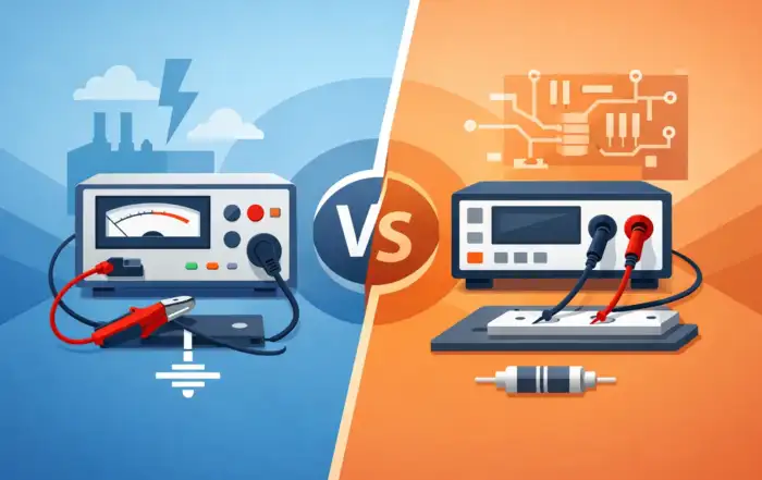
Ground Bond Tester vs Micro Ohmmeter
If you are evaluating a ground bond tester vs micro ohmmeter, the first question is not which instrument is better. It is what you need to prove. In regulated manufacturing and product validation, that distinction matters because these tools may both measure low resistance, but they do not answer the same engineering or compliance question.
A ground bond tester is primarily an electrical safety instrument. Its job is to verify the integrity of the protective earth path under relatively high test current, often as part of production line safety testing for appliances, medical equipment, industrial products, or other powered devices. A micro ohmmeter, by contrast, is a precision low-resistance measurement instrument used to quantify very small resistances in conductors, joints, windings, bus bars, switch contacts, and bonded connections. The overlap is real, but the intent is different.
Ground bond tester vs micro ohmmeter: the core difference
The simplest way to separate the two is this: a ground bond tester asks whether the earth continuity path can safely carry fault current, while a micro ohmmeter asks what the resistance actually is with high measurement resolution.
That difference affects current level, measurement method, compliance relevance, and even fixture design. Ground bond testing typically uses significantly higher current to stress the protective conductor path and expose weak terminations, undersized conductors, or marginal bonds that may not appear problematic at low current. A micro ohmmeter usually emphasizes measurement sensitivity and repeatability, often using Kelvin techniques to remove lead resistance and resolve values down into the micro-ohm range.
For an engineer selecting instrumentation, this is where confusion often begins. Both instruments can produce a resistance value. Only one is generally intended to support a formal ground continuity or protective earth test within a safety test sequence.
What a ground bond tester is designed to do
A ground bond tester is built around compliance-driven electrical safety testing. In production, it is commonly used after assembly to verify that accessible conductive parts are bonded to protective earth with sufficiently low resistance. The instrument applies a specified current through the ground path and measures the resulting voltage drop to calculate resistance.
The high-current aspect is not incidental. It is central to the test. Safety standards and internal quality procedures often require a meaningful current level because a low-current continuity check can miss issues that only appear when the connection is stressed. A loose fastener, oxidation at a bond point, thin plating, or an inadequate crimp may pass a light continuity test yet fail under higher current.
Ground bond testers also tend to fit into broader safety workflows. They are often paired with hipot, insulation resistance, or functional test stations in manufacturing environments where throughput, operator control, pass-fail limits, and traceable results matter as much as the raw measurement.
What a micro ohmmeter is designed to do
A micro ohmmeter is optimized for precise low-resistance characterization. This is the instrument you reach for when the actual value matters at fine resolution, when trending small changes over time is important, or when the device under test is not a protective earth path at all.
Typical applications include contact resistance on breakers and relays, resistance across bus bar joints, transformer winding checks, motor winding comparisons, cable resistance, weld evaluation, and material or assembly studies in R&D and quality analysis. The instrument is meant to resolve subtle differences, often using four-wire measurement to separate source and sense leads and reduce error from test lead and contact resistance.
That measurement architecture is why micro ohmmeters are so useful in the lab and in maintenance. They are designed to tell you whether a connection changed from 180 micro-ohms to 260 micro-ohms, not just whether it stayed below a production-line pass limit.
Test current changes the meaning of the result
One of the most practical differences in the ground bond tester vs micro ohmmeter comparison is test current. Engineers sometimes treat resistance as a single fixed property, but in real assemblies the measured result can depend on how the current interacts with interfaces, films, pressure points, and thermal effects.
A ground bond tester applies higher current because it is trying to validate the integrity of a safety-critical path under conditions closer to actual fault stress. This can reveal weak bonds that a lower-current instrument may not expose. If your requirement is tied to UL, IEC, or internal protective earth verification criteria, that matters.
A micro ohmmeter may use lower or selectable current, depending on the model and application. That is appropriate for sensitive components and precision measurement, but it can make the reading less representative of how a protective earth path behaves under a true safety test condition. The result may be accurate as a low-resistance measurement and still be insufficient as a compliance-oriented ground bond test.
This is the point where substitution creates risk. A micro ohmmeter is not automatically a replacement for a ground bond tester just because both report milliohms or micro-ohms.
Accuracy, resolution, and pass-fail logic are not the same thing
Micro ohmmeters generally win on resolution. If you need granular measurement of very low resistance, that is their purpose. They are the better fit for engineering analysis, incoming inspection of conductive assemblies, and predictive maintenance where resistance drift is part of the failure story.
Ground bond testers are built around a different priority set. They still need reliable resistance measurement, but they are also designed for repeatable high-current safety testing, operator protection, configurable limits, fast cycle times, and integration into controlled manufacturing processes. In many environments, the instrument must do more than measure. It must support a documented test method.
For that reason, the better instrument depends on whether you are looking for absolute low-ohm precision or a standards-aligned production safety result. Some organizations need both because product development, quality engineering, and end-of-line compliance do not ask the same question.
When to use a ground bond tester
Use a ground bond tester when the goal is to verify protective earth continuity on finished products or assemblies that must meet electrical safety requirements. It is the right choice for production lines, compliance verification, and final test cells where the bond must withstand specified current and where pass-fail thresholds need to be enforced consistently.
It is also the better choice when you need a safety tester that fits a larger validation sequence. In appliance, industrial equipment, EV charging, and medical manufacturing environments, ground bond is rarely an isolated measurement. It is part of a broader electrical safety regime.
When to use a micro ohmmeter
Use a micro ohmmeter when you need high-resolution low-resistance measurement for diagnostics, characterization, or condition monitoring. It is especially useful in R&D, service, maintenance, and quality investigations where understanding small resistance differences is more valuable than applying a compliance-style high-current earth test.
It is also the better instrument when the test object is not a protective earth path. Switchgear contacts, bus connections, cable assemblies, shunts, coils, and conductive joints often need precision resistance data rather than a ground bond determination.
Can one instrument replace the other?
Sometimes, but not cleanly.
If your task is purely diagnostic and no safety standard or internal test specification calls for a formal ground bond test, a micro ohmmeter may provide all the information you need. If your task is a required protective earth verification on a manufactured product, a ground bond tester is typically the correct tool.
The gray area appears in engineering labs and failure analysis. A team may use a ground bond tester to validate that an assembly passes the intended safety test, then use a micro ohmmeter to investigate why one unit trends close to the limit. That is not redundancy. It is using each instrument for what it was designed to reveal.
For organizations standardizing test infrastructure, it helps to separate three needs: compliance testing, precision characterization, and troubleshooting. Once those are defined, instrument selection becomes much more straightforward.
Selection criteria that actually matter
When comparing instruments, focus on the parameters that affect your use case. Current range matters because it defines whether the test is meaningful for protective earth validation. Measurement range and resolution matter because they determine whether small resistance changes are visible. Four-wire capability matters when lead resistance or fixture resistance could distort the result. Throughput, automation interfaces, data logging, and operator controls matter in production. Calibration traceability and standards alignment matter anywhere results may be audited or used for product release.
This is also where vendor expertise has value. In high-stakes environments, the instrument is only part of the solution. Test method definition, fixturing, limit selection, and repeatability under real operating conditions are what separate a nominal reading from a defensible measurement process.
Vitrek serves organizations that need that level of measurement discipline across safety test, precision instrumentation, and integrated validation workflows. For teams balancing compliance and engineering performance, choosing the right instrument up front usually saves far more time than trying to force one tool to cover every low-resistance test.
The practical answer to ground bond tester vs micro ohmmeter is simple: use the instrument that matches the claim you need to make. If you need to prove protective earth integrity under a safety test, use a ground bond tester. If you need to quantify very low resistance with fine resolution, use a micro ohmmeter. When the distinction is clear, your data becomes easier to trust and easier to defend.
Wire Harness Testing Methods: Continuity, Hipot, and Insulation Resistance Explained
A single wiring defect in a cable harness can cause anything from an intermittent fault to overheating, system failure, or fire. Visual inspection alone cannot detect damaged insulation, voltage-dependent shorts, or insulation resistance that has degraded below an acceptable threshold. Therefore, electrical testing of wire harnesses is critical across a wide range of applications.
This applies to automotive body harnesses, aerospace interconnects, multi-conductor medical cables, EV high-voltage systems, industrial power distribution assemblies, and other cable assemblies used in reliability-critical environments. Each conductor must be verified for correct connectivity, insulation integrity under voltage stress, and compliance with insulation resistance requirements before installation in systems where failure could become costly or hazardous.
Three core wire harness testing methods are widely used for electrical verification: continuity testing, hipot testing, and insulation resistance testing. Each method identifies failure modes that the others may not detect. As a result, manufacturers often combine all three methods to achieve more comprehensive wire harness validation. This post explains how continuity testing, hipot testing, and insulation resistance testing work, what each method measures, and how all three can be integrated into a single automated production workflow.

Why Wire Harness Testing Cannot be Replaced by Visual Inspection
Visual inspection can confirm that conductors are present and connectors are properly seated. However, it cannot verify whether a conductor is connected to the correct terminal, whether insulation remains intact under voltage stress, or whether contact resistance at crimp joint falls within specification.
Some key limitations of visual inspection include:
- Miswired conductors often appear identical to correctly wired conductors.
- Insulation damaged during assembly or contaminated by process fluids may show no visible signs of failure until voltage is applied.
- Contact resistance issues caused by poor crimp joints can typically only be detected through electrical measurement.
- Defects missed during visual inspection can lead to field failures that are significantly more expensive to address than production-stage defects.
- In regulated industries, field failures may also result in recalls, compliance violations, documentation burdens, and liability exposure beyond the direct repair cost.
Electrical Testing Methods for Wire Harness Verification
A harness can pass continuity testing and still fail hipot testing. Likewise, it can pass hipot testing while exhibiting unacceptable insulation resistance. For this reason, all three testing methods are used together to provide complete harness verification.
1. Continuity Testing: It verifies that every conductor is correctly connected and identifies opens, shorts, and miswires.
How It Works
Continuity testing applies a low voltage across each conductor path and measures resistance. A reading below the maximum acceptable threshold confirms that the conductor path is intact and correctly connected. A reading above the threshold, or the absence of current flow, indicates an open circuit or high-resistance connection.
To improve measurement accuracy in low-resistance applications, many continuity testers use four-wire Kelvin measurement techniques. Four-wire Kelvin measurement eliminates test lead and fixture resistance from the measurement, ensuring that the reading reflects only the conductor under test. This is particularly important when measuring low-resistance paths where lead and contact resistance could otherwise affect measurement accuracy.
What It Detects
- Open circuits occur when a conductor is broken or a terminal is not properly seated in its connector housing. Continuity testing identifies these conditions immediately because no current flows through the open path.
- Missing connections caused by assembly errors, such as a conductor not being inserted into the correct terminal position, are detected when an expected connection is absent.
- High-resistance connections caused by poor crimp joints or improperly assembled terminals produce resistance readings above the acceptable threshold, flagging the joint for inspection and repair before installation.
- Miswiring is detected when a conductor intended to connect point A to point B instead connects point A to point C. The continuity test identifies unexpected routing that does not match the programmed test profile.
What It Does Not Detect
Continuity testing uses only low voltage and therefore cannot detect insulation degradation between conductors. A harness with damaged insulation between adjacent conductors may still pass continuity testing because both conductors remain electrically intact and correctly connected. The insulation defect becomes apparent only under higher voltage stress.
2. Hipot Testing: Hipot testing detects insulation breakdown under high voltage stress, revealing defects that only appear when voltage is applied.
How It Works
Hipot testing, short for high-potential testing, applies high voltage between conductors or between a conductor and ground while measuring leakage current through the insulation. If the leakage current exceeds the acceptable limit at the specified test voltage, the insulation may contain a defect or weakened insulation path.
The test may be performed using AC or DC voltage. AC testing stresses the insulation in both polarities, while DC testing charges the insulation and is often effective at identifying resistive leakage paths. The choice between AC and DC hipot testing depends on the applicable standard and the characteristics of the assembly being tested.
What It Detects
- Insulation breakdown occurs when insulation fails completely under voltage stress. Damaged or improperly applied insulation may pass continuity testing while failing during hipot conditions.
- Voltage-dependent shorts conduct only at elevated voltage levels. These defects may remain undetectable during low-voltage continuity testing but become visible during hipot testing.
- Arc-over between adjacent conductors can occur when insulation damage or contamination creates a conductive path between closely routed conductors.
- Manufacturing defects in insulation, including voids, inclusions, and insufficient insulation thickness, can be exposed by the elevated stress applied during hipot testing.
What It Does Not Detect
Long cable runs behave capacitively when high voltage is applied. A hipot tester without sufficient output capability may struggle to maintain the required test voltage when large harnesses draw significant capacitive charging current. As a result, the actual test voltage may fall below specification.
This can result in false failures, where charging current is interpreted as leakage current, or incomplete testing because the required voltage level is not fully achieved. This issue is particularly common in automotive body harnesses, EV high-voltage cables, and aerospace interconnects with substantial cable lengths.
3. Insulation Resistance Testing: It identifies contamination, moisture ingress, and insulation degradation before complete breakdown occurs.
How it Work
Insulation resistance (IR) testing applies a DC voltage between conductors or between a conductor and ground and measures the resistance of the insulation itself. Results are typically reported in megohms, gigaohms, or teraohms.
A reading below the minimum acceptable threshold indicates insufficient insulation quality, even if complete insulation breakdown has not occurred.
What It Detects
- Moisture ingress and contamination are common causes of low insulation resistance in automotive and industrial harnesses. Water or process fluids entering through damaged or improperly sealed connectors can create low-resistance paths that IR testing detects effectively.
- Insulation degradation caused by exposure to chemicals, heat, or mechanical stress gradually reduces insulation resistivity over time. IR testing identifies this degradation long before catastrophic failure occurs.
- Surface contamination from handling, processing chemicals, or improper storage can deposit conductive residue on insulation surfaces. IR testing detects these conditions through below-threshold resistance readings that continuity and hipot testing may not reveal.
Why IR Testing Complements Hipot
Hipot testing identifies major insulation failures where insulation breaks down under elevated voltage stress. Insulation resistance testing, however, detects early-stage degradation before complete breakdown occurs.
A harness may pass hipot testing at the required voltage while still exhibiting insulation resistance values below acceptable limits. This indicates contamination, moisture ingress, or gradual insulation deterioration that may affect long-term reliability.
IR testing is particularly valuable in automotive and industrial environments where harnesses are exposed to temperature cycling, humidity, and fluid contamination throughout their service life.
Multi-Conductor Harness Testing: The Sequencing Challenge
The number of individual test combinations in a multi-conductor harness increases rapidly with conductor count. A four-conductor harness may require 20 individual test combinations to evaluate all conductor pairs, while a 24-conductor harness can require hundreds of combinations.
Performing hundreds of tests manually by reconnecting test leads between every combination is impractical in a production environment and increases the risk of skipped test points, incorrect connections, and improperly recorded results.
How Vitrek’s Automated Switching Systems Solve the Sequencing Challenge
Vitrek’s advanced cable testing platforms support applications ranging from high-voltage harnesses to mission-critical interconnects. These systems help manufacturers improve testing throughput, traceability, and quality assurance while supporting demanding industry and regulatory requirements.
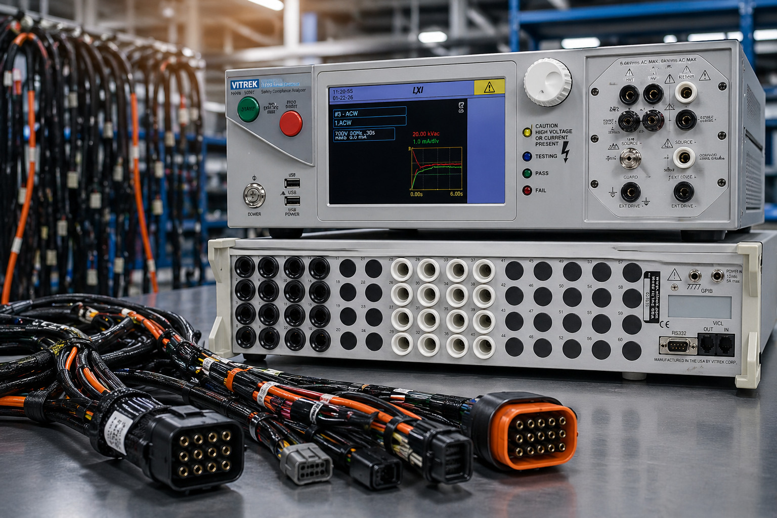
The Vitrek 964i High Voltage Switching System automatically routes test signals to each conductor combination in sequence without requiring manual reconnection between test steps. The system supports up to 999 sequential tests per automated run and provides switching speeds of up to 0.025 seconds between test steps.
During the automated sequence, the operator typically does not need to manually change test connections between measurements. The 964i manages signal routing, the 95X performs the electrical measurements, and QT Insite software automatically records results for every test combination.
Vitrek Test Equipment for Wire Harness Verification
Vitrek’s harness testing platform spans three instrument families covering a wide range of production environments, from general-purpose harness test lines to high-voltage EV and aerospace applications.
1. Vitrek 95X Series: Versatile Production Hipot Testing
The 95X Series provides AC and DC hipot, insulation resistance, and 4-wire continuity in a single instrument. It is designed for general production harness testing across automotive, industrial, appliance, and defense applications.
- AC hipot up to 6 kV standard; DC hipot up to 6.5 kV, 11 kV, or 15 kV depending on model
- Optional 30 kV AC external module for high-voltage transformer and distribution cable testing
- 500VA output power option (available on select models, including the 951i, 953i, 957i) for high-capacitance automotive and industrial harnesses
- 4-wire Kelvin ohmmeter with 100 µΩ resolution and range up to 100 kΩ
- Tera-ohm class insulation resistance measurement with DSP technology for stable low-leakage readings
- Pico-ampere leakage current resolution (up to 100 pA) for precise insulation characterization
- 40A ground bond capability on select models for appliance and industrial equipment safety testing
- 400 Hz AC testing support for avionics applications
- Direct control of up to 256 HV scanner channels; expandable to 640 channels via PC using QT Insite software
2. Vitrek V10X Series: Advanced Automation-Ready Testing
The V10X Series is Vitrek’s most advanced hipot platform, built for high-throughput automated production lines with complex harness configurations. It provides the same test functions as the 95X with expanded automation architecture, touchscreen workflow, and higher scanner channel capacity.
- AC hipot up to 10 kV and DC hipot up to 15 kV standard; optional 30 kV AC external module
- 500 VA minimum output power standard with optional 750 VA output capability for high-capacitance loads
- Configurable broadband arc detection with dual-parameter limits, including amplitude and pulse width (4–30 µs) for improved insulation breakdown sensitivity while reducing nuisance failures
- Pico-ampere leakage resolution (up to 100 pA) with phase angle measurement to separate resistive and capacitive leakage components
- Full-color touchscreen with graphical sequence editing and real-time measurement charts
- Multi-step sequence memory supporting 1,000+ steps in non-volatile storage with long-time retention
- 4-wire Kelvin ohmmeter with 100 µΩ resolution and measurement range up to 100 kΩ
- 40A ground bond capability on select models
- 400 Hz AC testing support for avionics and military applications
- Direct control of up to 1,600 HV scanner channels without external relay controllers
- Built-in PDF report generation and CSV export for audit-ready documentation
- Native SCPI control over Ethernet, USB, RS232, and optional GPIB for MES and SPC integration
- Applicable to automotive harnesses, aerospace interconnects, EV high-voltage systems, medical cables, appliance end-of-line testing, and LED driver safety compliance
3. Vitrek 98X Series Teraohmmeter/IR Tester: Dedicated High-Voltage IR
The 98X Series provides a dedicated high-voltage insulation resistance platform where insulation resistance testing is the primary requirement. It is also suitable for applications requiring IR testing beyond the voltage range supported by many standard hipot testers. The series supports DC output up to 6.5 kV on the 981i and up to 11 kV on the 983i, making it suitable for EV, solar, and high-voltage industrial applications.
- High resistance measurement capability up to 150 teraohms for advanced insulation characterization
- Stable 50 teraohm insulation resistance measurements with picoampere leakage current sensitivity
- Multi-dwell functionality allows IR tests at multiple voltage levels without returning to zero between steps
- Capacitance test modes for use with cable harnesses, solar panels, and other capacitive loads, which may not be fully supported by some conventional IR testers
- Continuously variable IR test voltage (1V resolution) across the full output range, and not limited to discrete voltage steps
- DSP technology for stable high-resistance readings in the presence of capacitive loading
- Direct control of up to 256 HV scanner channels; expandable to 1,020 test points via PC using QT Insite software
- Applicable to EV battery systems, solar panel arrays, multi-conductor cable harnesses, motor windings, and any application requiring IR testing above 1 kV
4. Vitrek 964i High Voltage Switching System
The 964i is the automated switching backbone for multi-conductor harness testing. It integrates with the 95X, V10X, and 98X Series instruments to route test signals across every conductor combination automatically.
- Supports automated execution of up to 999 sequential tests per run
- Switching speed of up to 0.025 seconds between test steps
- Eight relay card slots per chassis supporting up to 64 test points per unit
- Voltage ratings of 3 kV, 7 kV, 10 kV, and 15 kV to support different harness test requirements
- Reduces manual reconnection requirements, minimizes operator exposure to high voltage, and helps prevent skipped or duplicated test combinations
5. QT Insite Software
QT Insite provides the test sequencing, automation, and data management layer for the Vitrek harness testing platform.
- Barcode-triggered test profile recall reduces manual parameter selection and helps prevent incorrect test configuration for specific harness part numbers
- Per-assembly result logging by part number and lot number with PDF and CSV export capability
- Result database with searchable and filterable records for audit retrieval and traceability workflows supporting standards such as IATF 16949 and ISO 13485
- Support for multi-station parallel testing in high-volume production environments
Applicable Industries and Standards
Wire harness testing requirements span multiple industries, each governed by standards that define test parameters, documentation requirements, and acceptable test limits.
| Industry | Key Applications | Relevant Standards |
|---|---|---|
| Automotive | Body harnesses, powertrain wiring, CAN bus cables | USCAR-2, ISO 19642, LV 112, IATF 16949 |
| Electric Vehicles | HV battery cables, inverter wiring, charging interconnects | IEC 62196, USCAR-2, ISO 6469 |
| Aerospace & Defense | Avionics interconnects, cockpit harnesses, military cables | DO-160, MIL-STD-461, MIL-DTL-27500 |
| Medical Devices | Patient monitoring cables, imaging system harnesses | IEC 60601-1, ISO 13485 |
| Industrial Equipment | Motor control cables, power distribution harnesses | IEC 61010, IPC/WHMA-A-620 |
Ready to Verify Your Wire Harnesses?
Vitrek’s integrated wire harness testing platform supports automated continuity, hipot, and insulation resistance testing from a single production fixture connection. Contact the Vitrek team to learn how this testing approach can help improve defect detection, production throughput, traceability, and compliance documentation workflows.

Precision Power Analyzer Review Criteria
A failed power measurement rarely looks dramatic at first. More often, it shows up as a half-point efficiency discrepancy, an unstable harmonic reading, or a production test limit that keeps drifting between shifts. That is where a serious precision power analyzer review becomes useful – not as a feature checklist, but as a way to determine whether an instrument can hold up under real electrical test conditions.
For engineering teams working in EV, aerospace, medical, industrial electronics, or power conversion, the wrong analyzer does more than slow down test. It introduces uncertainty into validation, certification, and manufacturing decisions. A credible review has to examine metrology, dynamic behavior, system integration, and long-term usability together.
What a precision power analyzer review should actually evaluate
Many reviews overemphasize display features or basic measurement ranges. Those factors matter, but they are not the first place experienced users should look. In practice, analyzer quality is determined by how well it measures under non-ideal conditions: distorted waveforms, low power factor, wide frequency variation, transient loading, and mixed AC and DC environments.
A meaningful precision power analyzer review starts with base accuracy, but it cannot stop there. Accuracy specifications need context. Is the stated figure valid only at 23 C after a narrow warm-up period, or does it remain credible across the operating range your lab or production floor will actually see? Are voltage, current, power, phase, and frequency uncertainties specified clearly, or buried in separate notes that complicate comparison?
Phase accuracy deserves special attention. In inverter, motor drive, transformer, and switched-mode power applications, phase error can materially affect power calculations, especially at low power factor. An analyzer with excellent voltage and current accuracy can still produce misleading power data if phase performance is weak.
Accuracy is only part of the story
When engineers compare instruments, the headline ppm or percentage figure often gets the most attention. That is understandable, but incomplete. Precision power measurement depends on the full measurement chain: input conditioning, sampling architecture, timing integrity, current transducer compatibility, and computational methods.
For example, the analyzer may be paired with shunts, current transformers, or sensors that affect total uncertainty. If the instrument supports external transducers, the review should consider whether scaling, phase compensation, and calibration workflows are well implemented. If they are not, nominal analyzer performance may never translate into usable system performance.
Bandwidth is another area where specifications can look better on paper than they perform in application. If your work involves PWM motor drives, high-frequency switching power supplies, or harmonic-rich waveforms, the useful question is not simply maximum bandwidth. It is whether the analyzer captures and processes that content accurately enough for the metrics you care about, whether that is total power, harmonics, ripple, or conversion efficiency.
Dynamic response and waveform behavior
Static loads are easy. Real test environments are not. Loads step, drives switch, and control loops hunt. An analyzer review should ask how quickly the instrument settles after change, how it handles crest factor, and whether averaging settings hide events that matter.
In R&D, high-speed updates can help engineers diagnose control instability or switching loss behavior. In production, too much sensitivity can create noise in pass-fail decisions. The right balance depends on the use case. That is why dynamic response should be evaluated against the intended workflow rather than in isolation.
Harmonics, power factor, and compliance relevance
Power analyzers are often selected because a program needs more than volts and amps. Harmonic analysis, standby power testing, inverter efficiency, and regulatory verification all place different demands on the instrument.
A strong precision power analyzer review should examine harmonic measurement depth, frequency tracking, and computation transparency. Can the analyzer maintain accuracy when the fundamental shifts? Does it support the harmonic order and analysis mode required by the applicable standard or engineering method? Are power factor and related values stable under distorted conditions, or do they become unreliable when waveforms depart from ideal sinusoidal behavior?
This is especially relevant in pre-compliance and standards-oriented environments. If a lab is working toward energy efficiency validation, appliance testing, or power quality assessment, the analyzer should align with the test method in more than a general sense. Resolution, integration timing, filtering behavior, and reporting format can all affect whether data is usable for formal documentation.
Channel count and system fit
A single-channel analyzer may be sufficient for basic bench work. It is not sufficient for many modern power applications. Three-phase systems, inverter input-output studies, motor testing, and multi-node power distribution analysis quickly require more channels and tighter synchronization.
The best review questions whether the analyzer architecture matches the DUT. Can it support one-phase, three-phase, and mixed AC/DC measurements without forcing awkward workarounds? Are channels truly synchronized? Can users compare input and output power in one instrument with confidence, or do they need multiple devices and post-processing to complete the picture?
For development teams, this affects speed and confidence. For production teams, it affects fixture design, cycle time, and traceability. Buying more capability than needed can waste budget, but buying too little usually shows up later as a process limitation.
Software, automation, and data handling
An analyzer that performs well on the bench may still be a poor fit for automated test. Software support matters because measurement value increasingly depends on how data is captured, controlled, and exported.
A serious review should examine command set maturity, driver availability, SDK support, and integration with lab and production environments. If the instrument will be used in automated validation or end-of-line systems, remote control behavior, trigger options, logging stability, and timestamp integrity become just as important as front-panel usability.
Data export is another practical checkpoint. Engineers often need both raw waveform insight and summarized power metrics. If the analyzer restricts access to one or the other, troubleshooting becomes slower. If the software environment is unstable or overly proprietary, the total cost of ownership rises even if the instrument itself is technically capable.
Mechanical quality and serviceability matter more than expected
Industrial buyers do not purchase analyzers for occasional hobby use. They purchase them for repeated operation in laboratories, validation bays, and manufacturing cells where uptime and consistency matter. That shifts the review criteria toward mechanical design, calibration support, and vendor responsiveness.
Front-end protection, connector quality, thermal behavior, and enclosure durability all affect service life. So does calibration interval stability. If an analyzer requires frequent adjustment or has limited support infrastructure, the downstream cost can exceed any initial savings.
This is where established instrumentation manufacturers tend to separate from lower-cost alternatives. Documentation quality, application support, standards familiarity, and calibration traceability are not secondary benefits. In regulated or performance-critical environments, they are part of the instrument.
How to compare analyzers without oversimplifying the decision
The most reliable buying process starts with the test requirement, not the product brochure. Define waveform type, frequency range, expected uncertainty, channel needs, compliance obligations, and automation requirements first. Then compare instruments against that framework.
A useful evaluation usually includes bench verification with representative loads. If the application involves inverter outputs, test with inverter outputs. If low standby power matters, evaluate at the bottom end of the range where noise and offset become significant. If production deployment is the goal, verify remote operation and throughput before making a decision.
It also helps to separate must-have requirements from future-proofing preferences. A lab may want maximum bandwidth, but if the current program is centered on line-frequency efficiency and harmonics, channel synchronization and low power factor accuracy may deserve greater weight. The right analyzer is the one that reduces uncertainty in the measurements that actually drive decisions.
Precision power analyzer review: what experienced buyers notice
Experienced users usually spot the same patterns quickly. Strong analyzers provide clear uncertainty statements, stable results across varied conditions, credible harmonic and phase performance, and software that supports real test workflows. Weak analyzers rely on attractive headline specifications while leaving too much ambiguity in transducer handling, dynamic behavior, or standards alignment.
That does not mean there is one best instrument for every environment. A research lab, a compliance team, and a high-volume manufacturing line can all arrive at different purchasing decisions for valid reasons. The better question is whether the analyzer supports repeatable, traceable, application-relevant measurement without forcing users to compensate for its limitations.
For organizations evaluating platforms from companies such as Vitrek, that is often the deciding factor. The instrument has to perform not only as a measurement device, but as part of a larger quality and test infrastructure.
A good review should leave you with fewer assumptions, not more excitement. If the analyzer can hold accuracy under your waveform conditions, fit your compliance method, integrate into your workflow, and stay supportable over time, it is worth serious consideration. If not, no amount of interface polish will fix the measurement risk you inherit later.
Ground Continuity Tester Requirements
A ground continuity test rarely fails because the concept is complicated. It fails because the setup, current level, contact method, or pass criteria do not match the product, the standard, or the production environment. That is why ground continuity tester requirements matter. In regulated manufacturing, the tester is not just a box that outputs current and reads resistance. It is part of the evidence chain for electrical safety, product release, and audit readiness.
What ground continuity tester requirements actually cover
At a basic level, a ground continuity tester verifies that protective earth connections, chassis bonds, and other grounding paths maintain low enough resistance to carry fault current safely. In practice, the requirements extend well beyond measuring ohms. The instrument has to apply the specified test current, measure resistance with sufficient resolution, compensate for lead effects when needed, and produce repeatable results across operators, fixtures, and product variations.
For many teams, the real question is not whether the tester can measure continuity. Most can. The question is whether it can do so under the conditions required by the applicable standard and the manufacturing process. A lab evaluating one prototype may accept a slower, more manual workflow. A high-volume production line testing hundreds of units per shift needs faster current rise, stable contact resistance handling, clear pass-fail logic, and data capture that supports traceability.
Core electrical requirements for a ground continuity tester
The first requirement is test current capability. Ground bond and continuity tests are often specified at relatively high current compared with general low-ohms measurements because the goal is to stress the protective path enough to reveal weak joints, loose fasteners, undersized conductors, or poor terminations. Depending on the product category and standard, that may mean currents from a few amps up to several tens of amps. If the tester cannot source the required current for the required dwell time, the reading may look acceptable while the bond itself is not being meaningfully challenged.
Resistance measurement range and resolution are equally important. Protective earth paths typically have very low resistance, so the measurement system needs enough sensitivity to distinguish acceptable bonds from marginal ones. This is where instrument architecture matters. A tester designed for low-resistance measurement should provide stable readings in the milliohm region, not just broad continuity confirmation.
Another key factor is measurement method. For low-resistance testing, four-wire Kelvin measurement is often preferred because it minimizes the effect of lead and contact resistance in the measurement circuit. Two-wire methods may be acceptable in some applications, especially where the total path resistance limit is relatively generous, but they can introduce avoidable uncertainty. If the pass threshold is tight, four-wire capability is usually the safer engineering choice.
Current regulation also deserves attention. Some testers advertise a nominal current but allow notable variation under changing load conditions. In ground bond testing, output stability affects both repeatability and compliance confidence. A tester that delivers accurate, controlled current over the expected resistance range is better suited for formal safety testing than one that reaches target current only under ideal conditions.
Ground continuity tester requirements and compliance alignment
The most common mistake in specifying a tester is treating the instrument requirement as separate from the standard requirement. It is not. Ground continuity tester requirements should be built backward from the test method called for by the governing product safety standard, customer specification, or internal validation plan.
That means confirming the required current level, test duration, maximum allowable resistance, and test points. It also means checking whether the standard expects a dedicated ground bond test, a protective earth continuity test, or a similar verification under different terminology. The language changes across industries, but the compliance impact is the same. If your test method does not map cleanly to the requirement, your result may not stand up during review.
There is also a practical trade-off here. Some manufacturers specify more stringent internal limits than the governing standard to create production margin. That can be useful, but only if the measurement uncertainty, fixture repeatability, and contact method are tightly controlled. Otherwise, the organization may create false failures and line disruption without improving actual field safety.
Mechanical and fixture considerations matter more than many teams expect
A high-performance tester cannot compensate for a poor interface to the device under test. In many production environments, the dominant source of variation is not instrument accuracy. It is how current is injected and where voltage is sensed.
Probe pressure, oxidation at contact points, fixture wear, painted surfaces, and moving assemblies can all distort results. If the test point is not stable and repeatable, the measured resistance may reflect the connection between the probe and the product more than the product’s actual protective earth path. This is especially common on coated chassis, assemblies with multiple mechanical joints, or products where the grounding point is difficult to access.
Fixture design should support consistent placement, adequate contact force, and separation between current-carrying and sensing points when Kelvin methods are used. For higher-current applications, cable sizing and thermal behavior also matter. Undersized leads can heat up, drift, and reduce repeatability over a production shift.
Speed, throughput, and operator use
In manufacturing, ground continuity testing is rarely a standalone event. It is usually one station in a broader electrical safety sequence that may include hipot, insulation resistance, leakage, or functional checks. That makes cycle time a real requirement, not a convenience feature.
Fast test initiation, short stabilization time, and deterministic pass-fail output reduce bottlenecks. At the same time, pushing speed too aggressively can create problems. If contact settling is inconsistent or current ramp timing is too short, a fast result may not be a valid result. The right balance depends on the product and fixture quality.
Operator interface is another requirement that often gets overlooked until deployment. In high-mix environments, users need clear test recipes, visible limits, and simple prompts that reduce setup errors. For automated cells, remote control capability, digital I/O, and reliable system integration are just as important as front-panel usability. A tester that is electrically capable but difficult to automate can become an expensive constraint.
Data integrity, calibration, and auditability
For quality and compliance teams, a test result is only as useful as the record behind it. Ground continuity tester requirements should include data handling, not just measurement performance. At minimum, the system should support repeatable test execution, operator accountability where needed, and secure result storage tied to the unit under test.
This matters even more in medical, aerospace, defense, and other controlled industries where traceability is expected. A simple pass-fail light may be fine for operator feedback, but it is not enough for root-cause analysis or audit defense. Capturing measured resistance, actual test current, dwell time, timestamp, and product identifier creates a much stronger record.
Calibration and verification are part of the same discussion. The tester should support a calibration program with traceable standards and a practical interval based on use conditions, risk, and quality requirements. Some environments also benefit from daily or shift-start verification using known resistive references to confirm the combined performance of the instrument and fixture.
Safety and system design requirements
Because ground continuity and bond testing may involve elevated current, the tester itself needs safeguards appropriate to the application. That includes current limiting behavior, fault detection, thermal protection, and interlock compatibility where the broader system requires it. In bench use, this may be straightforward. In automated or multi-station systems, these protections become more critical.
Teams should also consider the test object’s behavior under current stress. Some products include sensitive assemblies, narrow conductors, or connectors not intended for high-current injection at every point. The test method may need to be adapted so the protective path is verified without overstressing adjacent circuitry or creating cosmetic damage at contact locations.
This is where application knowledge matters. A generic continuity requirement does not always translate directly into a safe and efficient production test. The best setup is the one that satisfies the standard while respecting the product’s actual construction.
Choosing the right tester for the application
When engineers evaluate instruments against ground continuity tester requirements, the right choice usually comes down to fit rather than headline specifications. A development lab may prioritize flexible programming and detailed measurement visibility. A production line may care more about throughput, fixture integration, repeatability, and minimal operator intervention. A compliance lab may focus on standards alignment, calibration traceability, and defensible records.
That is why specification reviews should include the full use case: required current, resistance range, measurement method, DUT geometry, fixture approach, automation needs, data requirements, and applicable standards. If any of those pieces are left vague, the tester may still work, but not with the confidence expected in a regulated or performance-critical environment.
For organizations standardizing across multiple test stations, there is also value in choosing a platform that supports consistent methods, software control, and serviceability. Vitrek and similar engineering-focused suppliers are often evaluated on that basis because the instrument is only one part of a long-term test infrastructure decision.
A ground continuity tester should do more than pass a specification review. It should produce stable, defensible measurements day after day, across shifts, fixtures, and product revisions. That is usually the difference between a tester that looks acceptable on paper and one that supports real manufacturing confidence.
Education & Training
Check out our recent presentation of Understanding Electrical Safety Testers at the 2018 San Diego Test Equipment Symposium!