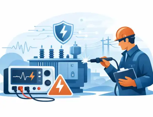
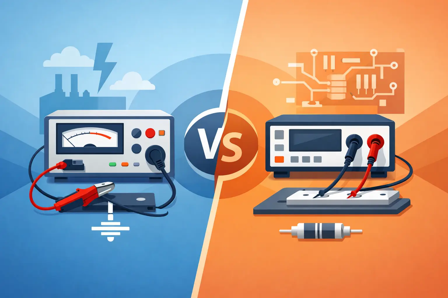
A motor drive that looks efficient on paper can fail a compliance review once harmonics, phase shift, or transient behavior are measured correctly. That gap is where a power analyzer earns its place. In engineering environments where efficiency claims, standby power limits, inverter performance, and repeatable validation matter, the quality of the measurement chain is not a detail. It is the test.
What a power analyzer actually measures
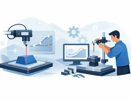
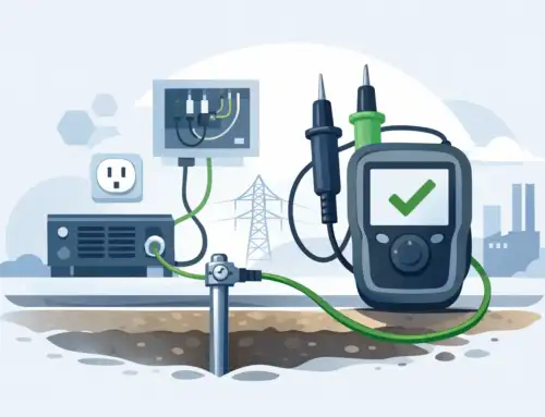
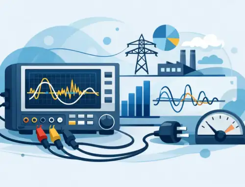
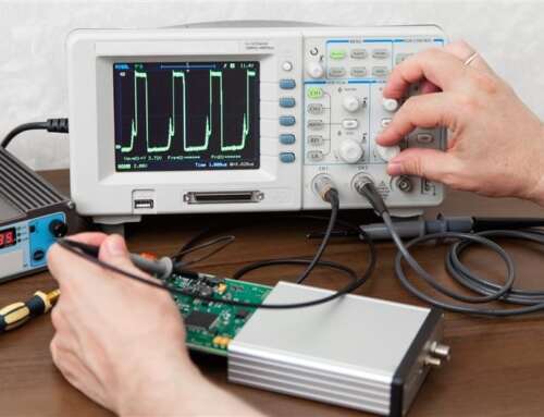
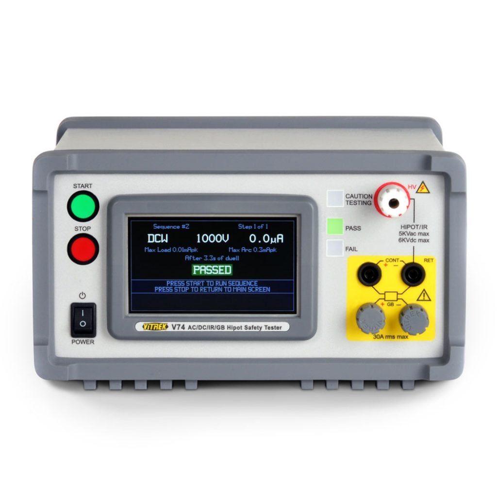
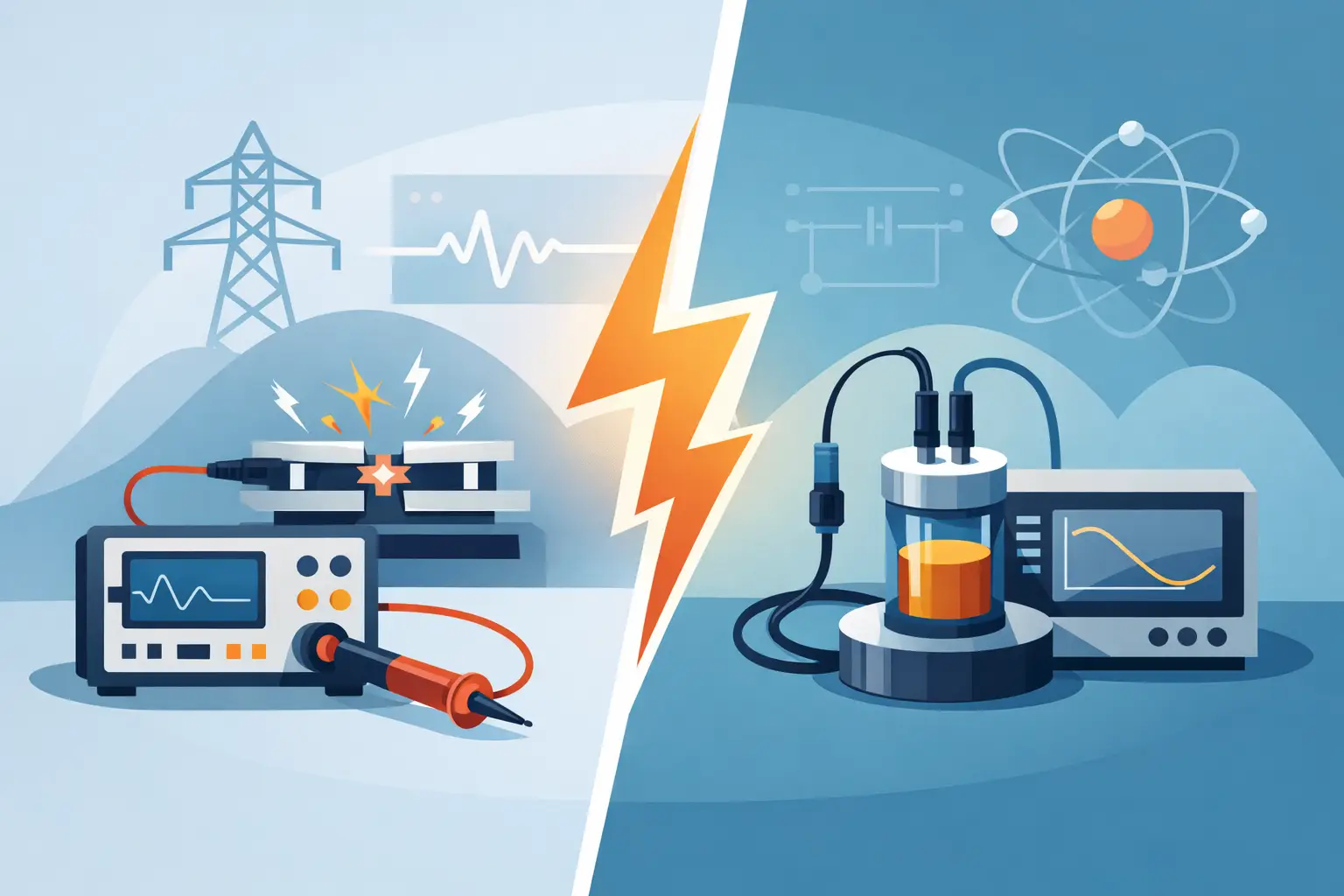
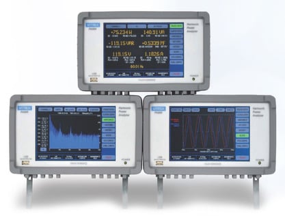
A power analyzer is designed to measure electrical parameters with a level of timing accuracy, bandwidth, and computational rigor that goes well beyond a basic power meter or benchtop DMM. At a minimum, it captures voltage, current, active power, apparent power, reactive power, power factor, frequency, and energy. In more demanding applications, it also resolves harmonics, phase angle, crest factor, inrush, and efficiency across multiple channels.
That distinction matters because modern electrical loads are rarely simple sinusoidal systems. Switch-mode power supplies, inverters, EV drivetrains, PWM motor controls, LED drivers, and battery systems introduce distortion and dynamic behavior that can make average measurements misleading. If voltage and current are not sampled with sufficient fidelity and aligned precisely in time, calculated power values can drift from reality.
For engineers working in regulated or performance-critical environments, the goal is not just to collect data. It is to quantify power behavior with low uncertainty and traceable confidence.
Why power analyzer accuracy is application-dependent
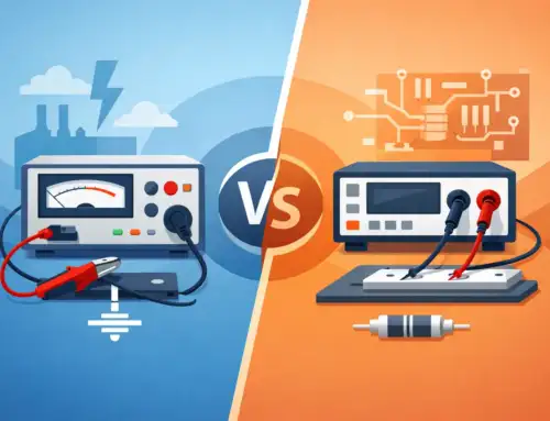
Accuracy is often reduced to a single published number, but experienced users know that power analyzer performance depends on how that number was derived and whether it matches the application. A headline accuracy spec may look strong while masking limits tied to range, frequency, crest factor, temperature stability, or phase measurement.
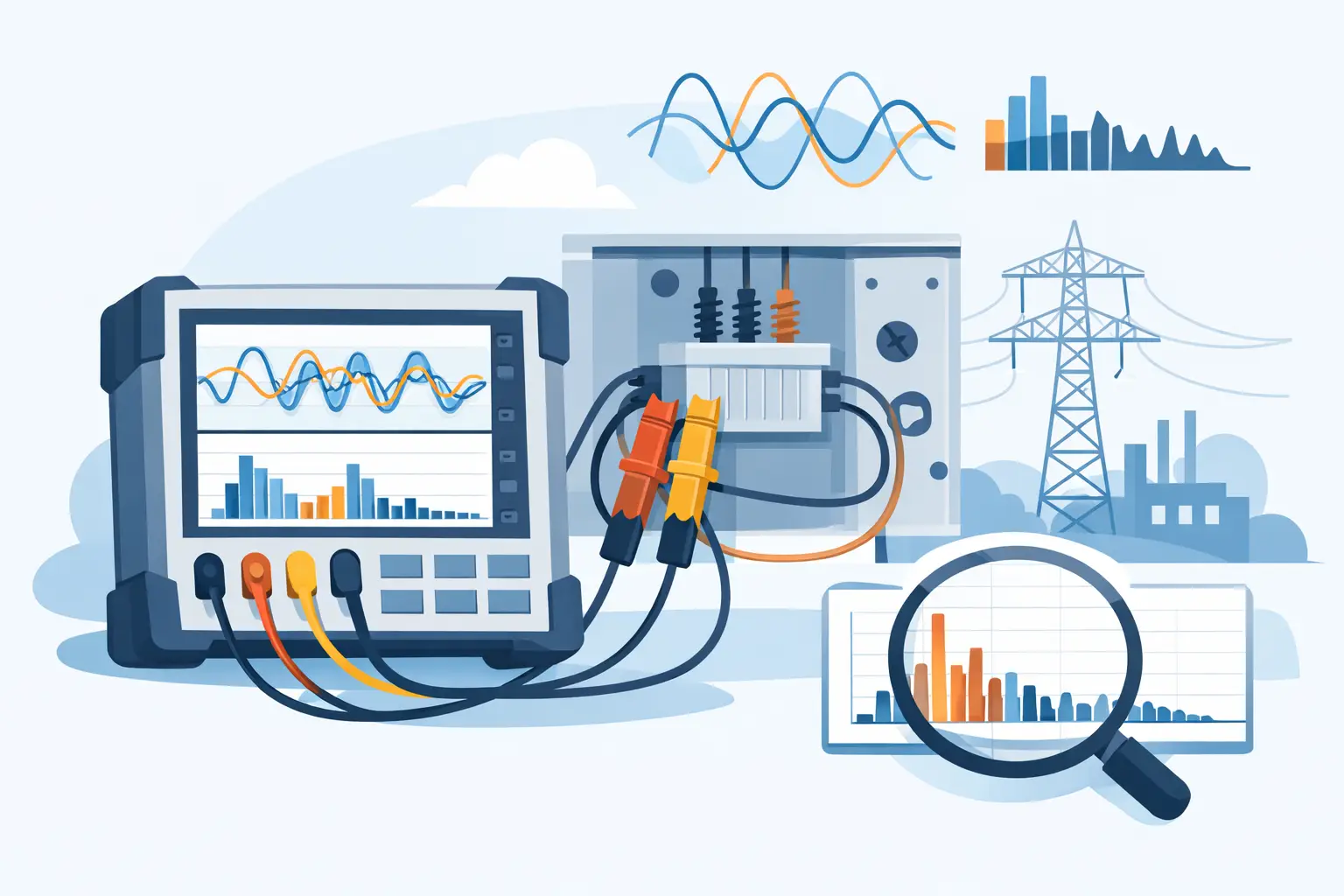
In practical terms, the right instrument for standby power validation may not be the right one for inverter efficiency mapping. Low-level current measurement requires strong sensitivity and stability near the bottom of the range. High-frequency switching analysis demands wider bandwidth and careful handling of distorted waveforms. Three-phase industrial systems add another layer, especially when channel-to-channel phase consistency is critical.
This is why specification review should start with the actual test profile. Consider waveform shape, expected power factor, frequency content, current amplitude, and whether the DUT operates in steady-state or fast-changing conditions. A power analyzer should be selected around those realities, not around a generic accuracy headline.
The role of phase accuracy
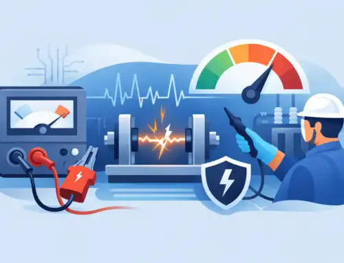
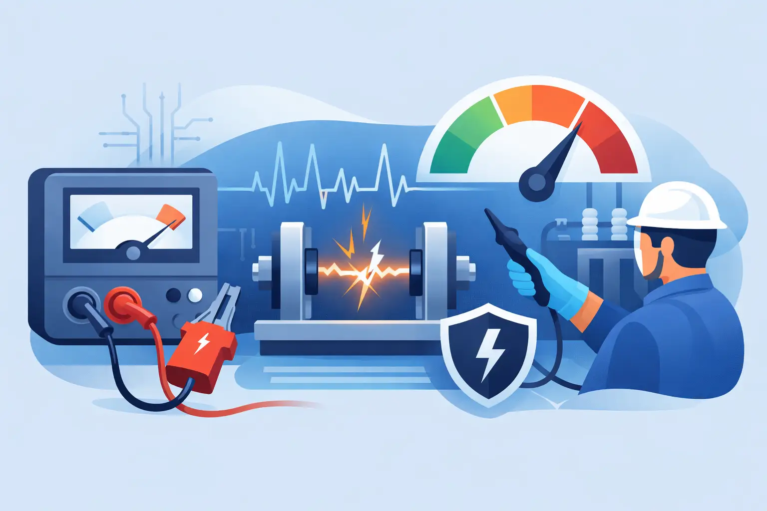
Phase error is one of the most overlooked sources of measurement uncertainty. In high power factor systems, small phase inaccuracies may have limited impact. In low power factor applications, that same error can materially affect watt calculations. This becomes especially relevant in motor drives, transformer testing, and reactive load analysis.
When evaluating instruments, phase performance should be reviewed with the same scrutiny as amplitude accuracy. For many applications, it is the difference between a believable efficiency result and one that triggers unnecessary design rework.
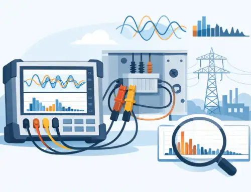
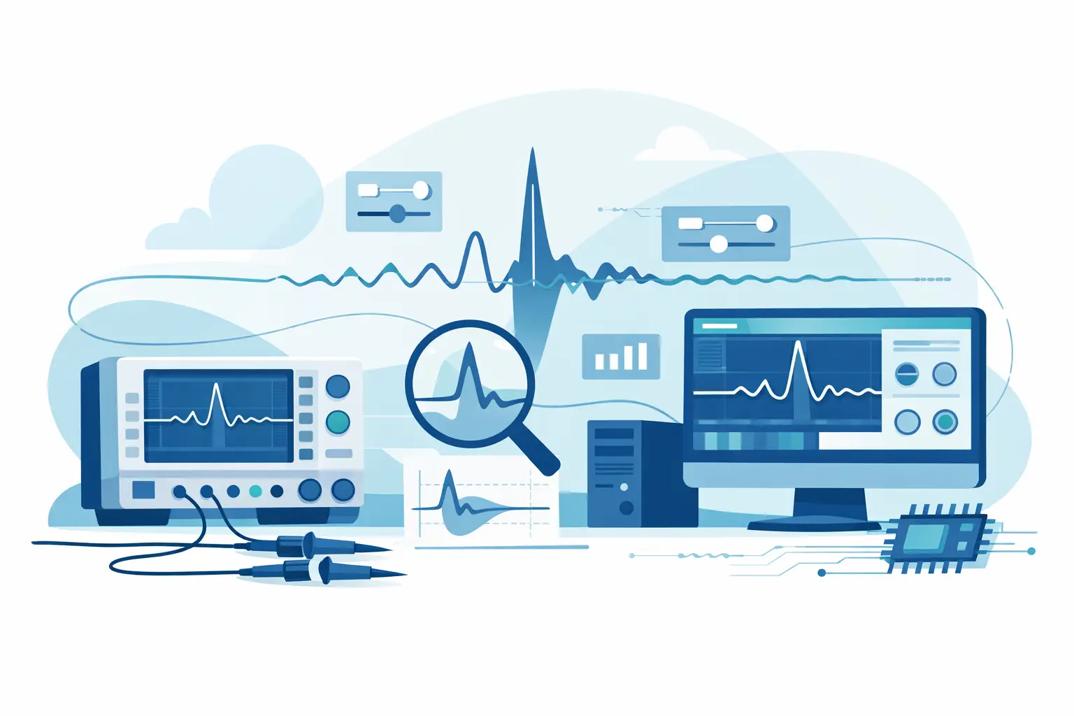
Bandwidth and harmonic content
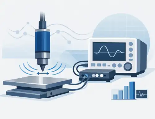
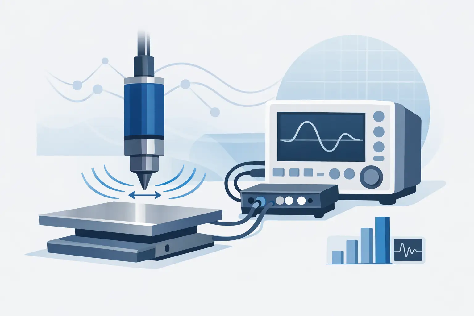
A pure 50 or 60 Hz measurement is no longer enough for many products. Fast-switching converters and PWM-controlled systems generate frequency content that extends well beyond the fundamental. If the analyzer cannot capture and process that content appropriately, total power and harmonic readings may not reflect actual operating conditions.
Wider bandwidth is not automatically better for every job, though. It can increase system cost and complexity, and in some test plans it may exceed what the standard or product requirement calls for. The better approach is to match bandwidth to the measurement objective and the expected spectral behavior of the DUT.
Where a power analyzer fits in real test environments
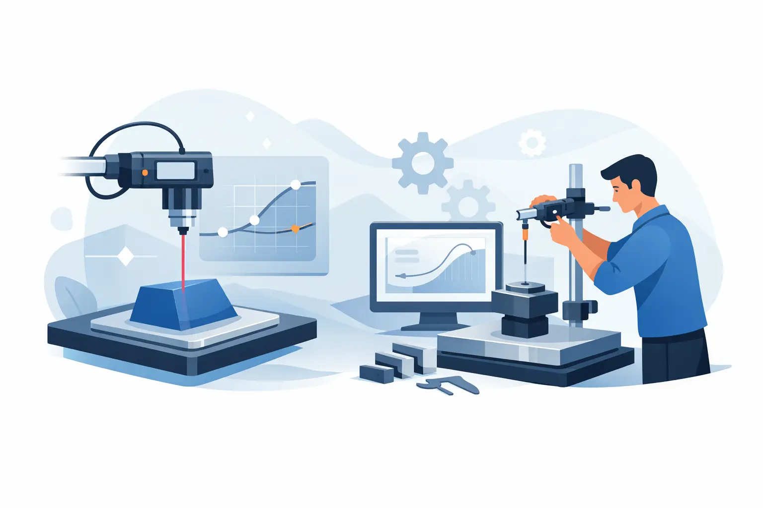
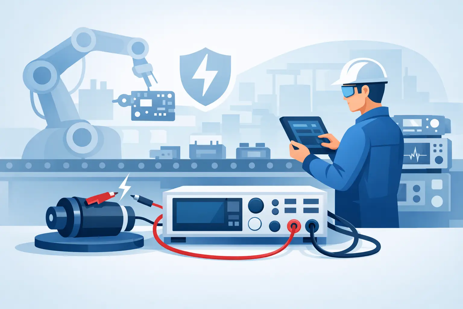
In R&D, a power analyzer is often used to validate design assumptions. Engineers compare topology changes, quantify conversion losses, and map efficiency under varying load conditions. The instrument becomes part of a decision process, not just a report generator.
In compliance and certification work, repeatability and standards alignment take priority. Test managers need measurements that can stand up to internal review, third-party scrutiny, and audit trails. Here, traceable calibration, stable long-term performance, and well-defined uncertainty matter as much as feature count.
In manufacturing, the emphasis shifts again. Throughput, fixture integration, automation support, and fast settling time can be more important than advanced waveform analysis. A production station may need a power analyzer that delivers dependable pass-fail data over thousands of cycles without constant operator intervention.
These are related use cases, but they are not identical. Instruments that perform well in one environment can be inefficient or oversized in another.
Key selection criteria engineers should weigh
The first question is channel architecture. Single-phase work may only require one input pair, but multi-phase systems, inverter testing, and comparative measurements often call for multiple synchronized channels. Channel count should support current needs and foreseeable expansion, especially in laboratories that test a wide mix of products.
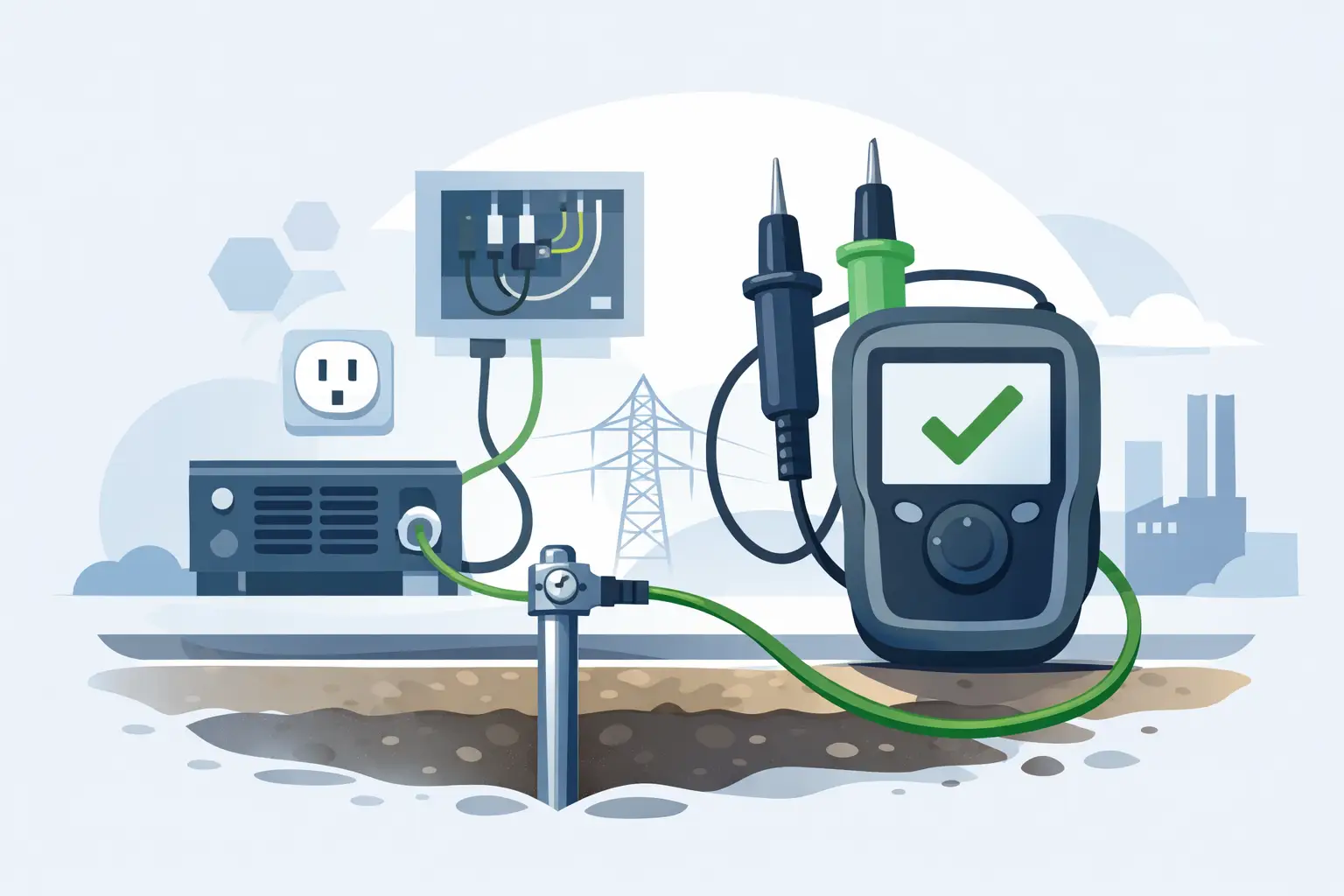
The second is input range and sensor compatibility. Some applications require direct current input, while others depend on shunts, current transformers, or external transducers. Compatibility with those accessories affects both flexibility and uncertainty. The measurement path is only as strong as its weakest link.
The third is data handling. Engineers increasingly need more than front-panel readings. They need waveform capture, numerical logging, software integration, and exportable datasets for deeper analysis. In automated environments, command support, APIs, and predictable remote operation are not optional features. They are part of the test system.
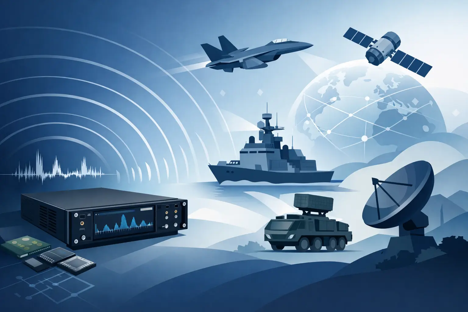
A fourth consideration is standards relevance. If the instrument will support energy efficiency, appliance, medical, aerospace, EV, or defense-related work, it should align with the measurement practices and documentation expectations common to those sectors. This does not always mean a single universal solution. It means selecting an analyzer that fits the technical and procedural demands of the application.
Common mistakes when specifying a power analyzer
One frequent mistake is buying for maximum specification rather than actual need. Overbuying can increase cost and setup complexity without improving the quality of the decision the test is meant to support. An R&D lab may justify broader capability, but a fixed production test station often benefits from tighter alignment to a defined test window.
Another mistake is treating current measurement as an accessory issue. Current transducers, shunts, and wiring methods influence bandwidth, burden, noise, and uncertainty. If those elements are selected casually, the analyzer itself cannot compensate for the resulting error.
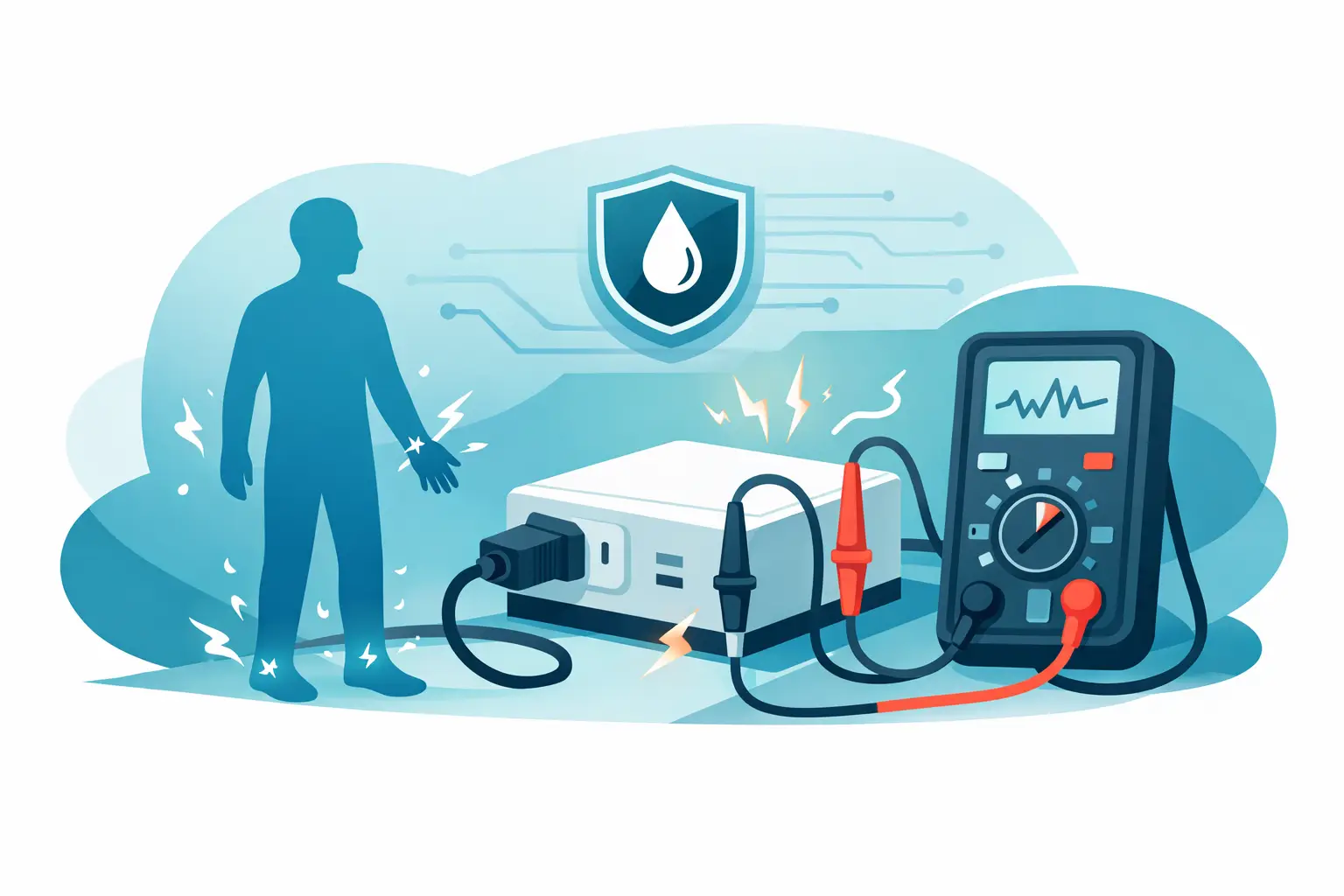
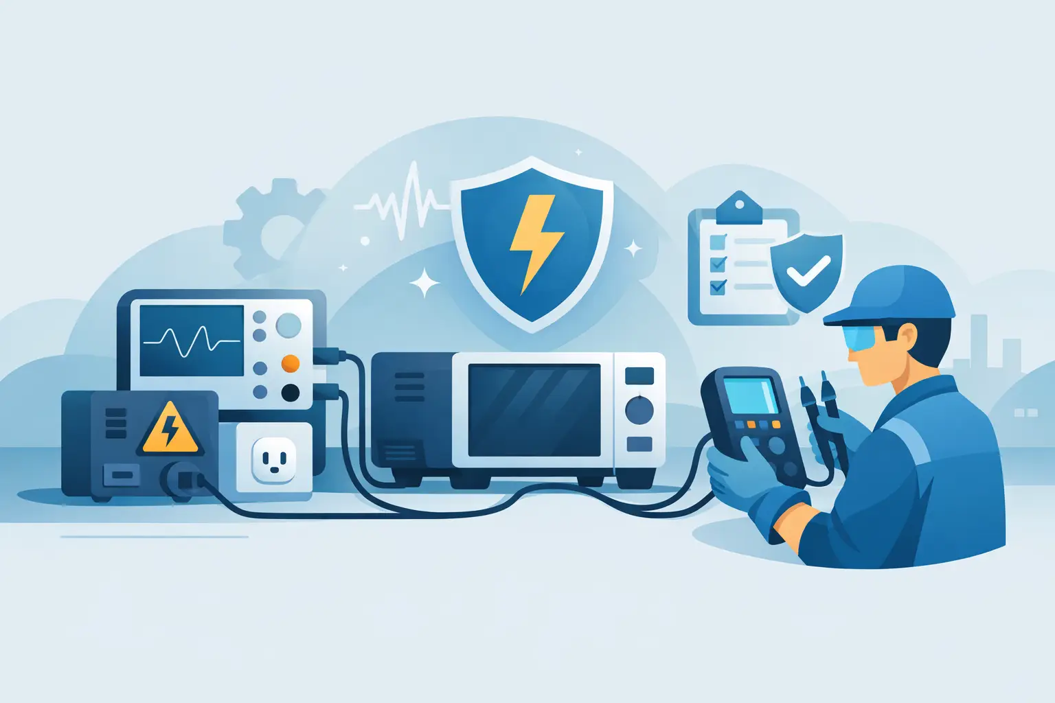
A third mistake is ignoring environmental and operational factors. Temperature drift, cable routing, grounding, fixture repeatability, and operator practices all affect results. In high-accuracy measurement, the instrument specification is only one part of the system performance.
There is also a software mistake that appears late in many projects. Teams verify that an instrument measures correctly at the bench, then discover that remote control behavior, data formats, or synchronization with other equipment complicate deployment. For automated systems, integration should be evaluated early, not after procurement.
Power analyzer data is only useful if it is credible
A good reading is not just one that looks stable on a screen. It should be explainable, repeatable, and consistent with the electrical behavior of the device under test. If efficiency changes by half a percent, the team should know whether that shift reflects an actual design improvement, a fixture variation, or measurement uncertainty.
That is why serious users pay attention to calibration traceability, documented uncertainty, and test method discipline. In sectors such as aerospace, medical, automotive, and defense, power data often informs qualification, compliance, warranty exposure, or design acceptance. The consequences of getting it wrong are larger than a single bad report.
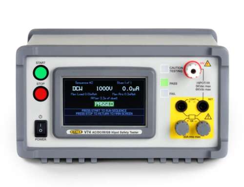
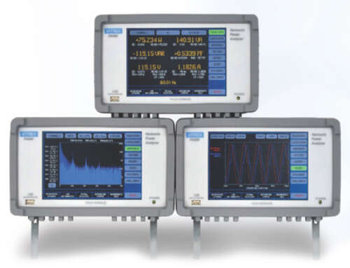
This is also where instrument build quality and vendor support become practical issues rather than purchasing line items. A power analyzer used in demanding labs or production cells has to remain stable over time, support recalibration workflows, and fit into a larger measurement infrastructure. Companies such as Vitrek are often evaluated on exactly those criteria because the instrument has to perform not only on day one, but through years of validation and manufacturing use.
Choosing for the long term
The best power analyzer is not the one with the longest feature list. It is the one that produces trustworthy data in the conditions that matter to your program, with accuracy that matches the decision you need to make. For one team, that means sub-percent efficiency analysis on a high-speed inverter. For another, it means reliable production confirmation of line power and energy consumption.
When the application is defined clearly, the instrument choice becomes much easier. Start with the waveform, the uncertainty target, the compliance context, and the automation plan. The right measurement platform should make those requirements easier to defend, not harder.


