A failed dielectric withstand test on a production line rarely starts as a dramatic event. More often, it shows up as inconsistent readings between stations, nuisance failures on otherwise good units, or a compliance review that exposes gaps in test coverage and traceability. That is where an electrical safety test system guide becomes useful – not as a basic checklist, but as a framework for choosing a system that produces repeatable, standards-aligned results under real operating conditions.
Electrical safety testing sits at the intersection of product compliance, operator protection, and manufacturing efficiency. If the system is underspecified, test results become hard to trust. If it is oversized or poorly integrated, throughput suffers and the test station becomes difficult to maintain. For engineering and quality teams, the right answer is usually not the cheapest tester or the highest voltage model. It is the system that matches the product risk profile, required standards, and production environment with the least uncertainty.
What an electrical safety test system guide should cover
At a minimum, an electrical safety test system includes the instrumentation needed to verify that a product can withstand expected electrical stress and maintain safe conductive paths where required. In practice, that often means some combination of hipot testing, insulation resistance measurement, ground bond testing, leakage current testing, and switching or automation hardware that ties those functions into a repeatable sequence.
The technical requirement depends heavily on the product class and the governing standard. A medical device, an EV subsystem, a consumer appliance, and an aerospace assembly may all require electrical safety validation, but the applied voltages, acceptable leakage limits, ramp profiles, and documentation requirements can be very different. That is why system selection starts with the standard and the use case, not with a feature list.
A good guide also accounts for where testing happens. R&D teams usually need flexibility, visibility into raw measurements, and the ability to adjust parameters as designs evolve. Production teams need controlled methods, user management, fixture integration, fast pass-fail decisions, and minimal setup variation between operators and shifts. One platform can support both environments, but only if it is designed with that range in mind.
Core test functions and where trade-offs appear
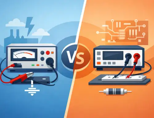
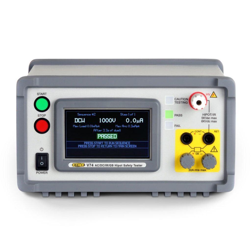
Hipot testing is usually the center of the system because it verifies dielectric withstand between isolated conductive elements. AC hipot and DC hipot each have practical advantages. AC testing better represents alternating stress in many end-use conditions and can reveal weaknesses that a DC test may not expose in the same way. DC testing generally reduces charging current effects and can be easier to interpret for some DUTs with higher capacitance. The correct method depends on the product and applicable standard, not preference alone.
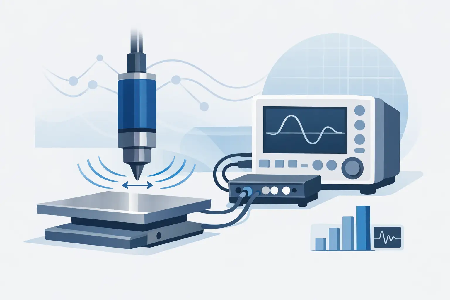
Insulation resistance testing often complements hipot by quantifying resistive leakage paths rather than only confirming breakdown withstand. It is particularly useful when you need more than a pass-fail threshold and want trend data that may indicate material degradation, contamination, or assembly variation. The trade-off is that insulation resistance measurements can be sensitive to environmental conditions, stabilization time, and fixturing quality.
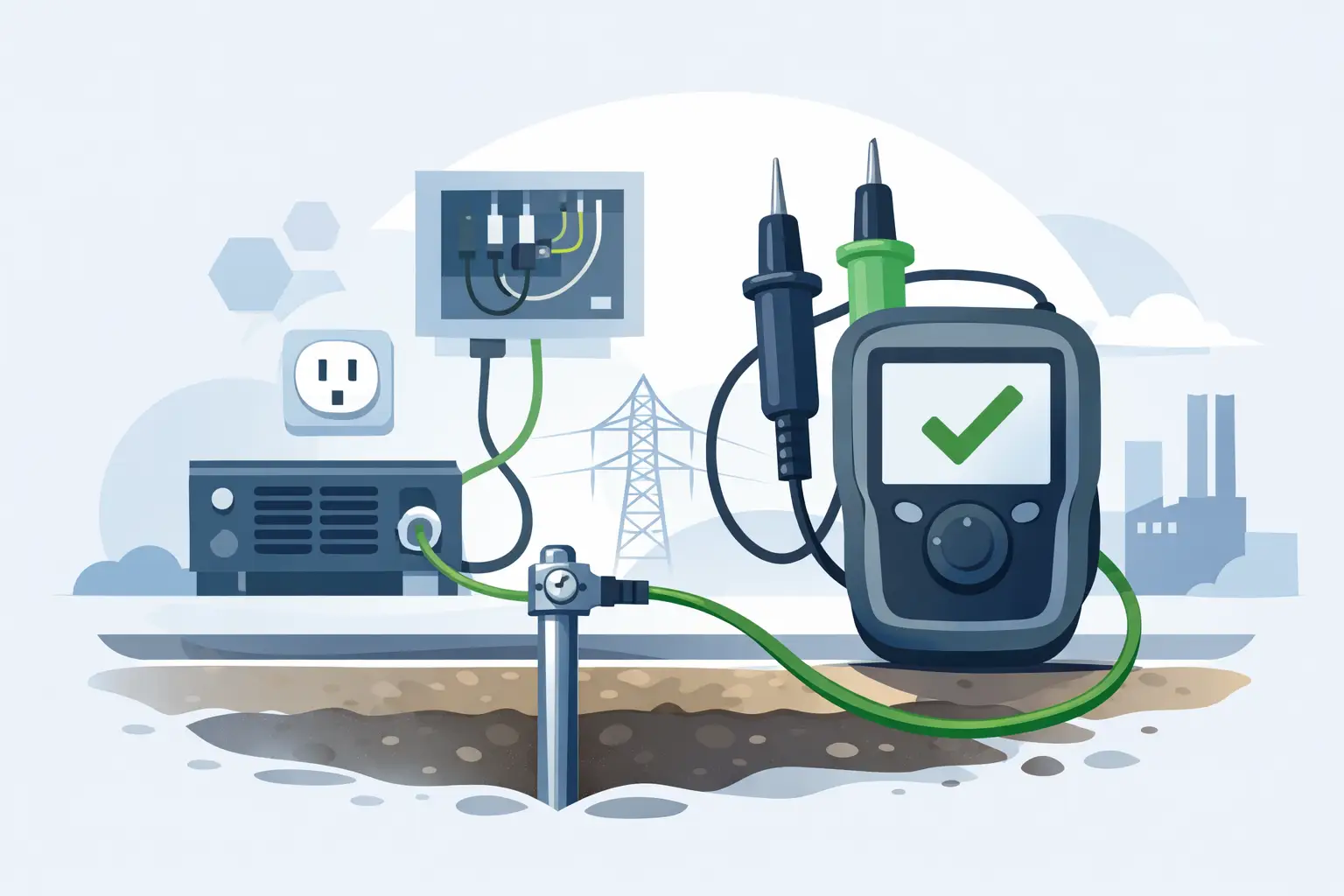
Ground bond testing confirms the integrity of protective earth connections by forcing significant current through the ground path and measuring resistance. This is straightforward in concept, but in production it can be affected by lead resistance, contact quality, and fixture wear. If the system does not compensate for those factors, marginal products may pass and good products may fail.
Leakage current testing becomes critical when end-user exposure is a concern, especially in medical, industrial, and powered consumer products. Here, measurement accuracy and standards interpretation matter more than raw voltage capability. A system that can generate high test voltages but cannot capture low-level current accurately is not well balanced for many safety applications.
System architecture matters as much as the tester
Many buyers focus first on the instrument chassis, but the system architecture often has a greater effect on daily performance. A test station is only as reliable as its switching, interlocks, fixtures, software control, and data handling. If those pieces are treated as afterthoughts, the result is usually downtime, inconsistent setup, and traceability gaps.
For multi-point testing, high-voltage switching must be designed for isolation integrity and repeatable channel performance. This becomes especially important in products with multiple nodes, harnesses, or subassemblies that require sequenced testing. Poor switching design can introduce leakage paths, timing variability, or maintenance issues that mask the actual DUT behavior.
Operator safety features are equally important. Interlocked enclosures, status indicators, remote e-stop integration, controlled discharge, and programmable ramp and dwell profiles are not optional details in high-voltage environments. They are part of the measurement system. The same applies to software controls that restrict unauthorized changes to test parameters. In regulated manufacturing, uncontrolled edits to a test recipe can create a compliance issue even when the hardware itself performs correctly.
How to specify the right electrical safety test system
The fastest way to overspend or underspecify is to select by maximum voltage alone. A better approach is to define the full test method. Start with the standard that governs the product, then map each required test to measurable electrical parameters, timing, and acceptance criteria. From there, review how the DUT behaves electrically. Capacitance, grounding topology, shielding, insulation materials, and connector geometry all influence test performance.
It is also worth separating engineering capability from production necessity. In R&D, you may want broader programmability, waveform control, or expanded measurement visibility to support failure analysis and design validation. In manufacturing, repeatability, user control, and cycle time usually take priority. Some teams choose one flexible platform for both; others reduce risk by keeping development and production configurations distinct.
Throughput should be modeled realistically. A station that looks fast on paper may slow down once charge times, discharge times, fixture loading, barcode handling, and operator prompts are included. This is one reason integrated systems often outperform collections of standalone instruments. Less manual intervention usually means fewer setup errors and more consistent test execution.
Calibration and traceability should be addressed early, not after deployment. Safety test systems are often used to support certification, release decisions, and audit records. That means measurement performance has to remain stable and documented over time. Buyers should evaluate calibration intervals, service support, adjustment control, and the availability of accredited processes that align with internal quality requirements.
Integration, data, and compliance control
In many facilities, the instrument is no longer the endpoint. Test results have to move into MES, quality databases, or device history records. That shifts the selection criteria beyond electrical performance and into communication stability, command structure, and software support. A system with strong measurement capability but weak integration often creates manual workarounds that undermine traceability.
For compliance-driven environments, data integrity matters as much as data collection. The system should support clear operator identification, recipe control, timestamped records, and result formats that are easy to review during audits or investigations. If a product fails in the field, engineering may need to reconstruct exactly how the original safety test was performed. That is difficult if settings were changed locally or records were stored inconsistently.
There is also a practical maintenance angle. Centralized test control, modular switching, and well-documented interfaces simplify troubleshooting and replacement. That reduces mean time to repair and makes line support less dependent on one internal expert who understands a custom script written years earlier.
Common mistakes in system selection
One common mistake is assuming the standard alone defines the complete test implementation. Standards set the framework, but the actual station design still has to account for DUT behavior, production variation, fixturing, and environmental conditions. Another is treating accessories as commodity items. In high-voltage testing, cables, connectors, probes, and switching hardware directly affect safety and measurement confidence.
Teams also run into trouble when they ignore operator workflow. If loading the DUT is awkward, if prompts are unclear, or if reset and retest procedures are inconsistent, station performance degrades even when the instrument specifications look strong. The best systems are technically rigorous and operationally disciplined.
A final issue is buying only for current programs. If your product mix is evolving toward higher voltage architectures, more complex assemblies, or stricter reporting requirements, some expansion headroom is usually justified. The goal is not excess capability for its own sake. It is avoiding a near-term redesign of the test infrastructure.
What good looks like in practice
A well-chosen system produces repeatable results across operators, shifts, and sites. It aligns with applicable standards, supports safe operation, and gives engineering enough visibility to investigate failures without slowing production unnecessarily. It also fits the reality of the facility – whether that means bench-level validation, automated end-of-line testing, or a multi-station architecture with centralized control.
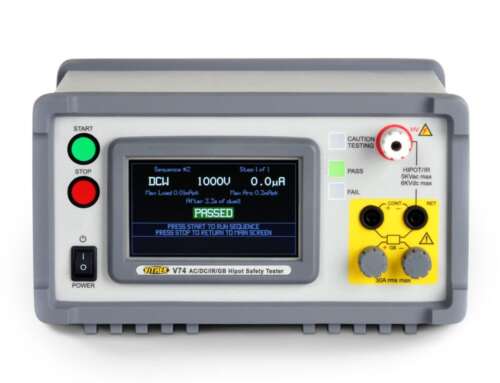
For organizations working in regulated and performance-critical sectors, electrical safety testing is not just a box to check before shipment. It is part of the evidence that a product was built correctly and verified with discipline. That is why many engineering teams look for partners with deep experience in hipot, insulation resistance, ground bond, switching, and measurement integrity, including manufacturers such as Vitrek that build for compliance-driven applications.
The right system is the one that makes the next audit, failure review, and production run less uncertain than the last.


