A 1% efficiency error can be the difference between passing a design review and reopening a thermal problem that was supposed to be closed. That is why an inverter efficiency measurement example matters beyond a simple ratio of output power to input power. In real test environments, switching frequency, waveform distortion, phase accuracy, bandwidth, and loading method all affect the answer.
For engineers validating motor drives, solar inverters, UPS stages, or DC-AC conversion modules, efficiency is not a single number. It is a measured result tied to operating point, temperature, modulation method, and instrument uncertainty. A useful example should reflect that reality.
Inverter efficiency measurement example: the basic calculation
At its simplest, inverter efficiency is:
Efficiency (%) = (Output Power / Input Power) x 100
If a DC-fed inverter draws 5,000 W from its input and delivers 4,700 W to the load, efficiency is 94.0%.
That math is straightforward. The hard part is obtaining input and output power values that are actually correct. Input may be relatively clean DC, but output is often pulse-width modulated, non-sinusoidal, phase-shifted, and highly dependent on load. If the instrument cannot capture true power under those conditions, the efficiency figure can look better or worse than the inverter really is.
A practical inverter efficiency measurement example
Consider a three-phase motor drive inverter under test in an EV subsystem lab. The unit is powered from a 700 V DC source and drives a dynamometer-connected motor at a fixed speed and torque point.
The measured DC input values are 700.0 V and 21.50 A. Input power is therefore 15,050 W.
On the output side, the inverter delivers three-phase AC to the motor. A precision power analyzer measures total real output power at 14,205 W under the selected operating condition. The efficiency is:
Efficiency (%) = (14,205 / 15,050) x 100 = 94.39%
That result is credible only if both measurements are synchronized, bandwidth is sufficient for the PWM content, and the analyzer is calculating real power rather than apparent power. In inverter testing, that distinction matters. Apparent power can be much higher than real power when harmonics and reactive components are present.
Now change one condition. As heat builds in the power stage, DC input current rises to 21.90 A while output power remains near 14,205 W. Input power becomes 15,330 W, and efficiency drops to 92.66%. Same inverter, same nominal setup, different thermal state. This is why efficiency maps are more useful than one-point numbers.
What needs to be measured
For a valid test, the input side usually requires DC voltage, DC current, and DC power. The output side requires true RMS voltage and current per phase, phase relationship, frequency, and total real power. Depending on the application, engineers may also record harmonics, crest factor, power factor, and switching ripple.
In a single-phase inverter, the channel count is lower, but the measurement problem does not necessarily get easier. Modified sine or PWM outputs can still challenge lower-grade instruments. In a three-phase system, channel synchronization becomes more critical because total output power depends on accurate phase-resolved acquisition.
A common mistake is to combine a DC meter on the input with a general-purpose clamp meter on the output and assume the resulting ratio represents efficiency. That approach can be acceptable for rough troubleshooting, but not for design validation, compliance documentation, or production correlation.
Test setup that supports repeatable results
A sound setup starts with a stable source, a controlled load, and a power analyzer designed for inverter-grade waveforms. For DC input, use appropriately rated voltage and current connections with known calibration status. For AC output, connect each phase according to the analyzer’s wiring method and verify scaling, sensor orientation, and grounding.
Load selection matters. A resistive load may be suitable for some standalone inverter stages, but it does not represent the behavior of a motor drive feeding an inductive machine. If the end application is a motor, generator, or grid-tied stage, the test load should reflect that operating condition as closely as practical.
Thermal stabilization matters too. If measurements are taken immediately after startup, losses in semiconductors, magnetics, and filters may not represent steady-state operation. Some programs intentionally measure cold, warm, and fully stabilized conditions to expose drift.
Where measurement error usually enters
Most bad efficiency numbers come from a few predictable sources. The first is inadequate bandwidth. Inverter outputs contain high-frequency switching components, and if the measurement system rolls off too early, real power can be mischaracterized.
The second is phase error. Even a small phase shift in voltage and current measurement channels can materially affect true power calculations, especially at lower power factor. This becomes more pronounced in motor drive and reactive load testing.
The third is poor current sensing. Rogowski coils, shunts, Hall-effect sensors, and current transformers each have strengths and trade-offs. Sensor selection should match frequency content, amplitude, isolation requirements, and uncertainty targets.
The fourth is averaging behavior. Some instruments report power over windows that are too short or not synchronized to the waveform pattern. With variable-speed drives and changing PWM schemes, unstable averaging can make efficiency appear noisy or inconsistent.
There is also a procedural issue: comparing input and output measurements taken at different times. If load, bus voltage, or temperature is changing, sequential readings can distort the ratio. Synchronous multi-channel acquisition is the safer approach.
Why instrument class matters in inverter testing
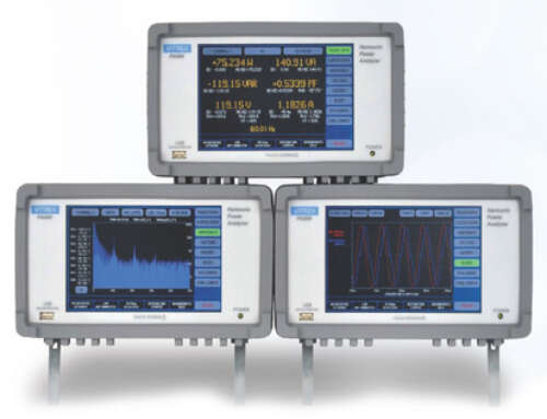
Inverter efficiency is a power quality problem as much as a power quantity problem. The measurement system has to resolve DC input accurately while also handling distorted AC output with confidence. That is where a precision power analyzer earns its place.
A suitable analyzer should provide high basic accuracy, stable phase performance, sufficient bandwidth, synchronized multi-channel measurement, and power calculations built for non-sinusoidal conditions. In regulated or high-consequence environments, traceable calibration and repeatable setup methods are just as important as the published specification.
For engineering teams moving from benchtop development to formal validation, this is often the transition point. A lower-cost meter may indicate trends, but it rarely provides the certainty needed for released data, customer reports, or cross-site correlation. Vitrek systems are typically selected in these environments because the measurement objective is not just to read power, but to defend the result.
Interpreting the result in context
A measured efficiency of 94.39% may be excellent or disappointing depending on topology, power level, switching frequency, and cooling strategy. Silicon carbide designs may target different efficiency behavior than silicon IGBT platforms. Higher switching frequency can improve waveform quality or control response while increasing switching loss. Heavier filtering may reduce EMI while adding insertion loss. There is always a trade-off.
This is why engineers often build an efficiency map instead of publishing one headline number. They test across load percentages, bus voltages, output frequencies, and temperatures. The resulting surface shows where the inverter performs best and where losses concentrate. That information is more actionable than a single point because it guides thermal design, magnetics optimization, control tuning, and component selection.
A short example with loss breakdown thinking
Suppose an inverter under test shows 95.2% efficiency at 50% load, 96.1% at 75% load, and 94.8% at full load. That pattern suggests fixed losses dominate at lighter load, while conduction and thermal losses increase near rated output. If efficiency also drops as heat sink temperature rises, semiconductor behavior or cooling margin may be part of the story.
If output waveform quality improves after increasing switching frequency but efficiency drops by 0.6%, the design team has a decision to make. Better control performance may justify the loss in some applications. In others, thermal headroom or energy consumption will carry more weight. Measurement should clarify that decision, not obscure it.
Reporting an inverter efficiency measurement example correctly
When documenting results, include more than the final percentage. Record input voltage and current, output real power, operating mode, load type, ambient temperature, inverter temperature if available, switching frequency, and instrument model or measurement class. If filters, probes, or external current sensors are used, identify them.
It is also good practice to state whether the result reflects steady-state operation and whether harmonics or non-sinusoidal waveforms were present. In design reviews and customer audits, that context is often what separates a useful test record from an incomplete one.
A good efficiency number should survive scrutiny. If another lab repeats the setup with equivalent instrumentation and controls, the answer should agree within a defined uncertainty band. That is the standard worth designing around.
The more demanding the inverter application, the less room there is for casual power measurement. When the data will drive thermal limits, compliance evidence, or platform-level design choices, the best test setup is the one that makes the result easy to trust.


