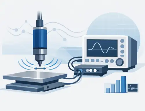
A displacement sensor that is off by a few microns can push an entire test process out of tolerance. In production metrology, vibration analysis, wafer inspection, and precision positioning, knowing how to calibrate displacement sensors is not a housekeeping task. It is part of measurement control.
Calibration does two things at once. It confirms whether the sensor is performing within specification, and it quantifies the uncertainty you should carry into the measurement process. That distinction matters. A sensor can still produce stable output while drifting enough to create bad acceptance decisions, poor trend data, or false machine diagnostics.
The right calibration method depends on the sensor technology, the required accuracy, the operating range, and the environment where the measurement will be used. Capacitive, laser, inductive, eddy current, and LVDT-based sensors do not respond to the same targets or error sources in the same way. The procedure should reflect that reality rather than forcing every sensor through the same generic check.
How to calibrate displacement sensors correctly
Start by defining the calibration objective. In some cases, you need a full multi-point calibration across the working range. In others, a verification at critical points is enough for periodic control. If the sensor is used for compliance-driven inspection or closed-loop machine control, the calibration plan usually needs to be more formal, traceable, and documented.
Before touching the instrument, review the sensor specifications and the application setup. Pay close attention to linear range, stand-off distance, target material, resolution, temperature coefficient, and output format. Many calibration problems start because the sensor is tested under conditions that do not represent actual use. A non-contact sensor calibrated against the wrong surface finish or reflectivity may look acceptable on the bench and fail in production.
The reference standard must have better accuracy than the device under test by an appropriate ratio for your quality system and uncertainty targets. A precision micrometer stage, laser interferometer, certified gauge block stack, or metrology-grade motion platform may be suitable, depending on the range and resolution required. The important point is that the reference must be traceable and stable enough to support the tolerance decision.
Environmental control is not optional when you are working near the limits of the sensor. Temperature drift, vibration, air turbulence, fixture movement, and electrical noise can all distort the result. If the displacement sensor normally operates in a thermally controlled lab, calibrating it on an open shop floor introduces a mismatch. If it normally runs in production conditions, a pristine lab calibration may not fully predict installed performance. That is why some organizations maintain both bench calibration records and in-situ verification data.
Set up the calibration system
Mount the sensor rigidly and align it to the direction of travel of the reference standard. Misalignment introduces cosine error, which is easy to underestimate in short-range work. The fixture should hold both the sensor and target stable through the full motion range without backlash or tilt.
Choose a target that matches the sensing principle. Capacitive sensors are highly sensitive to target geometry and material. Eddy current sensors require conductive targets and can shift with alloy changes. Optical displacement sensors may respond differently to matte, polished, or translucent surfaces. If the production target is unique, calibrating with a generic substitute can build systematic error into the measurement chain.
Warm-up time matters. Many displacement sensors and their controllers need thermal stabilization before the output settles. Follow the manufacturer guidance and, if the application is especially tight-tolerance, verify drift over time rather than assuming the published warm-up period is sufficient.
Once the setup is stable, zero the system if the sensor architecture requires it. Some sensors use a taught reference point, while others rely on fixed scaling in the controller. Record the initial condition, including stand-off distance, ambient temperature, humidity if relevant, target description, and the serial numbers of both the sensor and the calibration standard. Good calibration data is only useful if another technician can reproduce the setup.
Perform a multi-point calibration
For most displacement sensors, a single-point adjustment is not enough. Run a multi-point sequence across the intended measurement range, with enough points to reveal nonlinearity, hysteresis, and localized error. Five points may be adequate for a simple check. Ten or more is common when tighter accuracy is required or when the output will be used for compensation models.
Move the reference standard in known increments and allow the reading to settle at each point. Record both the commanded or certified reference position and the sensor output. Then repeat the sequence in the reverse direction. The difference between the up-scale and down-scale data indicates hysteresis, mechanical play, or thermal instability in the setup.
Pay attention to where the sensor will actually be used. If only the central 20 percent of the sensor range is used in production, that region deserves denser calibration points than the unused extremes. A full-range calibration is still useful, but the decision limits should reflect the real measurement zone.
If the sensor supports adjustment, apply calibration coefficients or scaling changes only after the initial as-found data is captured. That as-found record is essential for drift analysis and quality documentation. After adjustment, repeat the full data run and save the as-left results separately.
Evaluate the data, not just pass or fail
A sound calibration process does more than confirm the output matches the reference at a few points. Review offset, linearity, repeatability, hysteresis, and noise. Depending on the sensor and application, one of these terms may matter more than the others.
For example, in static thickness measurement, offset and linearity may dominate. In dynamic vibration measurement, bandwidth, phase response, and noise floor may be just as important as static position accuracy. A sensor can pass a slow bench calibration and still underperform in the application if the calibration method ignores the actual measurement dynamics.
Uncertainty should also be estimated. That includes the reference standard uncertainty, environmental effects, fixture stability, repeatability of readings, alignment error, and any interpolation or conversion error in the controller or software. In regulated or mission-critical environments, calibration without an uncertainty statement is often incomplete from a quality perspective.
If the data shows a problem, avoid assuming the sensor is defective immediately. The source may be target mismatch, cable damage, grounding issues, contamination on the optical path, improper gain settings, or motion stage error. Troubleshooting should proceed through the full measurement chain.
Common mistakes when calibrating displacement sensors
The most common mistake is calibrating against a convenient target instead of the real one. The second is relying on only one or two points and missing nonlinearity. The third is ignoring mounting and alignment, especially for non-contact sensors where small angular errors can create measurable position error.
Another frequent issue is treating controller electronics and the sensor head as separate when they function as one measurement system. If the controller, extension cable, or signal conditioning changes, the calibration may no longer apply. The calibrated configuration should match the fielded configuration.
It is also easy to overlook cleaning and surface condition. Oil film, dust, oxidation, or a scratched reference surface can shift readings enough to matter in high-resolution work. For shop-floor systems, contamination control is often part of calibration discipline, not an afterthought.
How often should you calibrate?
There is no universal interval. Calibration frequency should be based on risk, usage, environmental exposure, historical drift, and the consequence of bad data. A sensor used in continuous production near tolerance limits may need more frequent verification than the same model used occasionally in an R&D fixture.
A good starting point is to review drift trends over several cycles and adjust the interval based on evidence. Stable systems may justify longer intervals. Sensors exposed to heat, vibration, frequent handling, or aggressive cleaning often justify shorter ones. For many organizations, the best approach is scheduled calibration supported by interim checks using a stable reference artifact.
In high-accuracy applications, it is also worth distinguishing between laboratory calibration and installed system verification. Bench calibration confirms instrument performance under controlled conditions. Installed verification confirms that the full measurement setup still performs as intended after mounting, integration, and production exposure.
Documentation and traceability
Calibration records should be detailed enough to support audits, troubleshooting, and long-term trend analysis. That means recording environmental conditions, standards used, test points, as-found and as-left data, uncertainty where required, operator, date, and any adjustments made.
For organizations working under ISO-based quality systems or customer-specific compliance requirements, traceability is not a paperwork exercise. It is the link between the reported number and a defensible measurement process. When displacement data is used to qualify parts, validate machinery, or support failure analysis, traceable calibration is part of the evidence chain.
If your operation relies on non-contact metrology for precision manufacturing or diagnostics, calibration deserves the same engineering attention as sensor selection. The best results come from matching the method to the sensing principle, using traceable reference standards, and treating the installed measurement system as a controlled asset rather than a black box. That approach reduces uncertainty before it reaches your product, your process, or your final decision.


