Grounding is a fundamental aspect of electrical and electronic systems, vital for ensuring both safety and noise reduction. The chassis, typically a conductive metal frame or enclosure, not only protects internal components but also serves as a common grounding point and return path. Effective chassis grounding helps prevent stray voltages and fault currents, thereby reducing shock hazards and enhancing overall system safety. This becomes especially important in electrical safety testing and leakage current measurements, where improper grounding can compromise both accuracy and protection. For this reason, engineers and technicians must understand how chassis grounding influences electrical safety testing, its role in preventing electrical faults, and its importance in maintaining compliance with safety standards. This post highlights the critical role of chassis grounding in safeguarding equipment, personnel, and measurement integrity.

What is Chassis Grounding?
Chassis grounding or equipment grounding is a process wherein the metal frame or enclosure of electrical equipment is electrically connected to the physical earth (PE) or a common ground reference point. This connection creates a low-resistance path that allows electrical current to flow safely away from the equipment in the event of an electrical fault. Chassis grounding therefore acts as a safety valve for electricity that prevents voltage buildup on surfaces humans may touch.
Chassis Grounding Vs. Signal Grounding Vs. Earth Grounding
There are various grounding types with their specific purposes and applications. While these grounding types may be interconnected, here are some differentiating points between chassis ground, signal ground, and earth ground (PE).
- Chassis ground: This grounding type ensures safety and helps prevent and manage faulty current by providing a low-impedance path. It is meant for handling current of hundreds of amperes. It requires less than 1 ohm resistance to the ground. It is directly connected to the electrical system’s main ground and requires 12 AWG or heavier-gauge conductors for most applications.
- Signal ground: This grounding type serves as an electrical reference point for circuit operation and signal integrity. It provides a stable voltage reference (0V) for electronic circuits and signals. It handles low currents ranging from milliamps to a few amps and manages low impedance at signal frequencies. It may be isolated from other grounds to prevent noise and ensures normal functioning of analog and digital circuits.
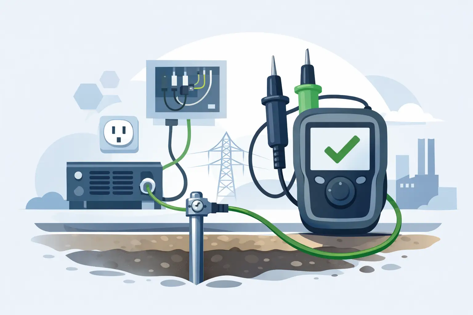
- Earth ground: Earth ground is the physical connection to the earth through buried electrodes, rods, or plates. Its resistance to earth is 25 ohms or less. It serves as the ultimate voltage reference and provides a path for lightning and surge currents to dissipate safely. It is physically connected to the earth and is mandatory for the grounding of electrical systems as per electrical codes.
Common Use Cases
Here are some use cases and applications of chassis, earth, and signal grounding.
Industrial control panels: Industrial control panels contain sensitive control circuits and high-power equipment. Also, most of the time, they operate in harsh industrial environments and elevated temperatures and hence have some grounding challenges. Here are the grounding requirements for panels.
- Chassis grounding must be used for all metal enclosures, motor frames, and equipment housings and these items must therefore be connected to the facility’s equipment grounding system.
- Signal grounding must be used for control circuits, PLCs, and instrumentation that require clean signal grounds through isolated ground bars.
- Earth grounding must be used to connect to the facility’s earth grounding system for lightning protection and meet electrical code compliance requirements.
Here are some pointers for efficient grounding implementation.
- Ensure separate ground bars for power circuits and control circuits within the same panel.
- Use star-point grounding configuration to minimize ground loops.
- Ensure all metallic components including hinged doors and removable panels are bonded.
- Ensure isolation for sensitive instrumentation
Medical devices: The main challenge here is overcoming the possibility of micro-shock hazards to ensure patient safety. Hence, there are stringent safety standards for medical device grounding. Here are some grounding requirements for medical devices and special considerations.
- Chassis grounding must be used for all accessible conductive surfaces with redundant paths
- Signal grounding must be used for patient-connected circuits that often use isolated signal grounds to prevent ground loops that could cause interference.
- Earth grounding must be used to connect the device to the facility’s isolated power system ground.
- The leakage current limits are much lower and stricter, up to 100 microamps maximum for patient-connected devices.
Here are some grounding implementation pointers.
- Operating rooms and critical care areas use isolated power systems with line isolation monitors to prevent noise.
- Patient monitors use isolated signal grounds to prevent interference between monitoring channels.
- Portable medical devices often use double-insulated construction.
- Medical IT power systems provide additional safety through isolation transformers.
Consumer electronics: The grounding requirements for consumer electronics depends on the type of appliance or device. For instance, Class I devices comprise computers, kitchen appliances such as microwaves & refrigerators, power tools, and workshop equipment. Class II devices comprise laptops, smartphones, and other small and portable devices.
Here are some grounding implementation pointers for Class I and Class II devices.
Class I devices
- Ensure three-prong power cords with equipment grounding conductor.
- Ensure the metal chassis is bonded to the grounding pin.
- Signal grounds are typically connected to chassis ground through a single point
Class II devices
- These devices can function with two-prong power cords or a battery.
- Ensure double insulation between hazardous voltages and accessible parts.
- Ensure signal grounds isolated from any connection to earth
- Extensive use of isolation transformers and optical isolators
Why is Chassis Grounding Important?
Chassis grounding is significant for the following reasons.
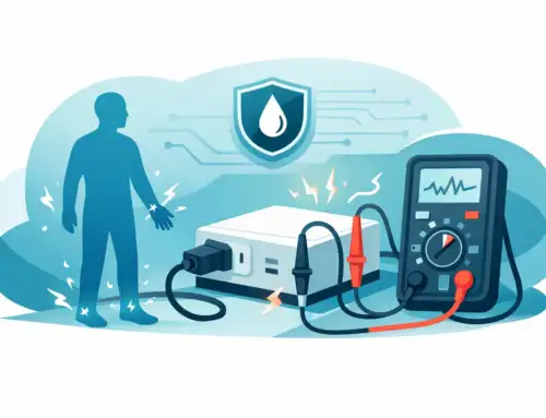
- Electrical Shock Protection: Chassis grounding protects users from electrical shock in case of insulation failure. It ensures that fault current flows through the ground path rather than through any human touching the equipment. This is especially critical in high-voltage applications or wet environments.
- Fault Current Management: Chassis grounding provides a low-impedance path for fault current to trip protective devices such as circuit breakers. The low-impedance ground path is crucial because it allows enough fault current to flow to quickly trip overcurrent protection devices. A high-impedance ground path might not carry sufficient current to activate breakers or fuses promptly.
- Voltage Stabilization: Chassis grounding prevents floating voltages on exposed conductive parts. Without proper grounding, conductive enclosures can “float” to unpredictable voltages due to capacitive coupling from internal circuits, creating shock hazards even during normal operation.
- Ground Loops: While grounding is essential for safety, improper implementation can create ground loops that introduce noise. Single-point grounding or star grounding configurations help mitigate this.
- Testing Requirements: Most standards require ground bond testing during production, typically using currents of 10-40A for a specified duration to verify the integrity of ground connections.
- Reduction in EMI: EMI/RFI need to be particularly managed in complex electronic systems with sensitive components. Here, proper chassis grounding provides a stable reference plane and helps contain electromagnetic emissions.
An Introduction to Chassis Grounding Safety Standards
Here is an overview of standards referencing chassis ground.
- IEC 61010: This standard provides the general safety requirements for electrical equipment. It requires protective earthing for accessible conductive parts and specifies ground bond resistance limits which are typically ≤0.1Ω for portable equipment.
- IEC 60601: This standard for medical electrical equipment is particularly stringent, often requiring redundant grounding paths and lower leakage current limits due to the critical nature of medical applications.
- IEC 62368: This standard replaced IEC 60950, and is the one that focuses on information and communication technology. It emphasizes hazard-based safety engineering, focusing on energy sources and their safeguarding rather than just prescriptive requirements.
- NEC Article 250: This standard covers industrial control panels, bonding, ground bond requirements, and test current thresholds. It outlines comprehensive grounding and bonding practices, including clear distinctions between equipment grounding conductors and grounding electrode conductors.
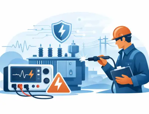
Grounding in Hipot and Leakage Current Testing Instruments
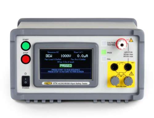
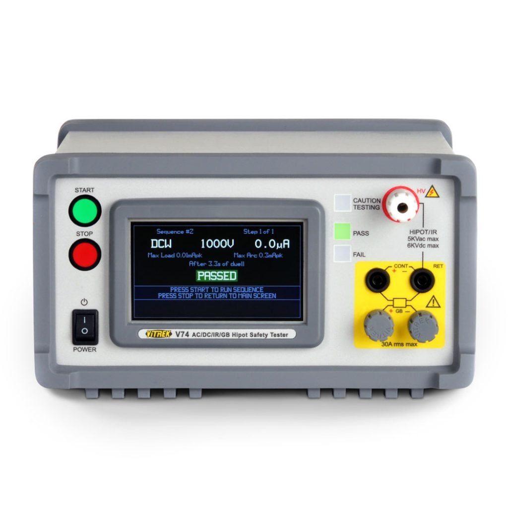
Vitrek’s 95X and V7X series hipot testers integrate ground bond testing alongside AC/DC hipot, insulation resistance, and leakage current testing. This ensures solid ground connections and testing ground bonds as part of comprehensive electrical safety testing. Here are the chassis grounding details in Vitrek’s Hipot and electrical safety testers

- Chassis ground as return path in hipot testing: In dielectric withstand (hipot) testing, high voltage is applied between live conductors and ground, with leakage current measured through the return path to ground. During these tests, hipot is applied to both conductors and leakage is measured in the return circuit through the ground connection. Vitrek’s V7X series testers can measure leakage current to 100 nano-amps accurately. Vitrek’s DC Hipot test can measure leakage current from 0 to 15,000 volts, ensuring no excess current is flowing to the chassis or other external environment. Here, the ground connection serves as both the measurement reference and safety protection.
- Role of grounding in leakage current measurement accuracy: A solid chassis ground connection minimizes electromagnetic interference that could affect the sensitive current measurement circuits, especially when measuring nano-amp level currents. Proper grounding technique prevents multiple return paths that could create measurement errors. Capacitive coupling between conductors and ground can mask true resistive leakage if not properly analyzed during testing.
- Test configurations: The testing is performed for line-to-chassis, neutral-to-chassis, and ground-to-isolated circuit configurations. The 964i Hi-Voltage Switch of Vitrek’s V7X series hipot testers can auto-index through complex tests at 0.025 seconds reconnect requiring consistent ground references across multiple test configurations.
How Vitrek Testers Support Proper Grounding Practices
Vitrek’s testers have advanced features that support appropriate grounding practices. Here are some features.
- The Vitrek 95X tester comes with a built-in ground bond test function such as 40A test.
- These testers have safety interlocks and automatic ground checks.
- Their precision leakage current detection feature helps identify ground insulation breakdown.
- These testers are compatible with high-voltage switching systems for multi-point testing.
- They use QT Insite or test automation to ensure ground compliance logging.
Understanding chassis grounding of test measurement equipment is essential to ensure safety and accurately measure leakage current limits. It is necessary for manufacturers to follow established standards and compliance related to grounding methods. Vitrek’s Advanced Hipot testers provide the precision and features necessary to perform these measurements effectively. Vitrek’s hipot testers serve as perfect tools to verify, test, and document grounding integrity effectively.


