A power analyzer vs oscilloscope decision is rarely about which instrument is more capable in general. It is about whether the test requires defensible power results, visibility into fast electrical events, or both. In power electronics development and production test, confusing those roles can create measurement uncertainty, extend debug cycles, and leave compliance-relevant performance questions unanswered.
An oscilloscope shows how voltage and current change over time. A power analyzer measures the electrical quantities derived from those waveforms with controlled accuracy over defined measurement intervals. Both may display voltage, current, frequency, phase, and harmonic content, but their measurement architectures and intended outcomes are different.
Power Analyzer vs Oscilloscope: The Core Difference
A precision power analyzer is designed to measure real power, apparent power, reactive power, energy, power factor, efficiency, and harmonic quantities. It samples voltage and current channels synchronously, applies calibrated gain and phase characteristics, and calculates results over a specified integration period. Its value is measurement integrity: repeatable numerical results that can support design verification, efficiency mapping, comparative testing, and documented performance claims.
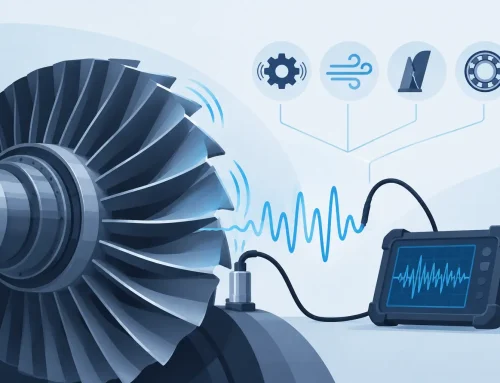
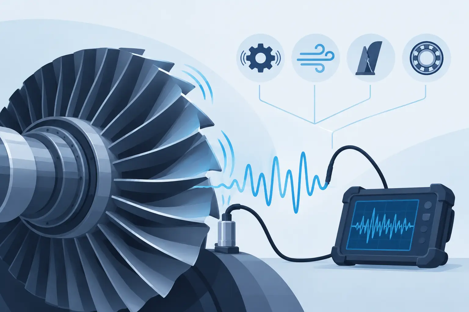
An oscilloscope is designed to capture waveform behavior. Its high bandwidth, fast sample rate, deep memory, and triggering capabilities make it especially useful for observing switching edges, transient overshoot, ringing, gate-drive timing, inrush current, and intermittent faults. It answers questions such as: What happened at this instant? Which transition caused the fault? Is the current probe saturating? Is a switching node exceeding its expected voltage limit?
The distinction matters because a clean-looking waveform does not prove accurate power measurement, and a stable power reading does not explain a transient failure. Engineers often need both perspectives during development, but not necessarily at the same stage of the test.
What a Power Analyzer Measures Better
Power analyzers are purpose-built for applications where small differences in watts, phase angle, or efficiency matter. This includes traction inverter characterization, motor and drive testing, appliance energy consumption, power supply evaluation, battery charge and discharge studies, and converter loss analysis.
For example, measuring inverter efficiency requires accurate input and output power measured at the same time. A 0.5% error in each power measurement can become much more significant when calculating the difference between two large values. If a drive receives 10 kW and delivers 9.7 kW, the loss is only 300 W. Uncertainty in the input and output channels directly affects confidence in the calculated efficiency and loss result.
Phase accuracy is equally important. On AC systems, real power depends on the relationship between voltage and current. A small timing error between channels can produce a meaningful power error, especially at low power factor or when measuring high-frequency, pulse-width-modulated waveforms. Precision power analyzers specify performance for this task, including channel synchronization, phase response, and measurement accuracy across operating conditions.
A power analyzer also provides integrated results over user-defined periods. That is valuable when the device under test has load variation, control-loop behavior, or operating cycles that make a single instantaneous capture unrepresentative. Energy measurement, for example, is inherently an accumulated quantity. It requires stable time-based integration, not merely a screen capture of a waveform.
Measurements that benefit from a power analyzer
A power analyzer is generally the primary instrument when the result must quantify electrical performance rather than simply reveal waveform shape. Typical measurements include input and output power, conversion efficiency, energy consumption, RMS voltage and current, power factor, harmonic power, frequency, torque and mechanical power when integrated with appropriate transducers, and loss distribution across operating points.
For regulated products and high-volume manufacturing, traceable calibration and repeatability are also central requirements. The measurement must remain meaningful across benches, operators, facilities, and production lots.
What an Oscilloscope Reveals Better
Oscilloscopes excel when the failure mechanism is fast, intermittent, or timing-dependent. In a switched-mode power supply, an oscilloscope can reveal drain-source voltage overshoot, transformer ringing, gate-drive crossover behavior, switching-node slew rate, and current spikes that occur in nanoseconds or microseconds. These events may contribute to electromagnetic interference, device stress, false triggering, or unexpected thermal loss.
The instrument’s trigger system is often the deciding factor. Engineers can trigger on a runt pulse, pulse width, logic condition, serial-bus event, or a voltage threshold that appears only during a fault. Segmented memory can capture many short events over a long test interval. Advanced probes can help maintain signal fidelity at high voltage, high frequency, or in circuits with demanding common-mode conditions.
Oscilloscopes can calculate power mathematically from voltage and current probes. This is useful for observing instantaneous power, identifying switching loss intervals, or correlating electrical behavior with a control event. However, that capability should not automatically be treated as equivalent to a dedicated power analyzer.
The final result depends on probe accuracy, channel skew, bandwidth settings, sample rate, deskew procedure, scaling, offset performance, and mathematical processing. Those variables can be managed carefully, and scope-based power analysis is often essential for switching-loss investigation. But for precision efficiency measurement or long-duration energy testing, it may not offer the same uncertainty performance or workflow as a power analyzer.
When You Need Both Instruments
The most effective power-electronics test setups frequently use a power analyzer and an oscilloscope in parallel. The analyzer establishes the system-level result. The oscilloscope identifies the waveform behavior behind that result.
Consider a motor drive that misses its efficiency target at a particular speed and torque point. The power analyzer can confirm the operating condition, quantify the efficiency shortfall, and show whether input power, output power, or harmonic performance has changed. The oscilloscope can then examine PWM timing, current ripple, dead time, gate behavior, and DC bus disturbances. One instrument identifies the magnitude of the problem; the other helps isolate its cause.
This division of labor is also useful during design verification. Use the oscilloscope to validate switching behavior, protection response, and transient margins. Use the power analyzer to produce repeatable performance data across voltage, load, speed, temperature, and frequency conditions. For automated test systems, the analyzer’s numerical outputs and control interfaces also support systematic data collection and reporting.
Selection Criteria Beyond the Data Sheet Headline
Bandwidth and sample rate attract attention, but they should not dominate every selection. Select the instrument based on the measurement objective, the signal environment, and the required uncertainty.
For a power analyzer, evaluate voltage and current ranges, basic accuracy, phase accuracy, channel count, bandwidth, crest-factor capability, harmonic analysis functions, synchronization, integration methods, and communication interfaces. Consider whether the system must measure multiple phases, DC and AC signals simultaneously, or mechanical inputs such as torque and speed. The current sensor is part of the measurement system, so its range, bandwidth, calibration, and phase performance require the same scrutiny as the analyzer itself.
For an oscilloscope, assess analog bandwidth, sample rate, memory depth, trigger capability, channel count, probe selection, isolation requirements, and the expected common-mode voltage. A high-bandwidth scope with an unsuitable probe can still produce misleading results. Differential measurement techniques, probe loading, grounding practices, and safety ratings are especially critical on high-voltage inverter and mains-connected systems.
Do not overlook test repeatability. If two engineers cannot reproduce a result because trigger settings, probe placement, or acquisition conditions differ, the measurement may be useful for debugging but weak for verification. Document connection points, sensor orientation, bandwidth limits, integration windows, scaling, and calibration status as part of the test method.
Safety and Measurement Integrity
Power conversion equipment can combine hazardous voltage, high fault current, fast edges, and substantial stored energy. Instrument selection must include the measurement category and voltage rating of the instrument, probes, current sensors, leads, and fixtures. A grounded oscilloscope probe connected incorrectly to a floating or high-side node can create an equipment-damaging short and expose personnel to risk.
Use appropriately rated isolated or differential probes where required, follow established lockout and discharge procedures, and validate the measurement setup before applying full operating power. In production and compliance-sensitive environments, calibration traceability and defined verification intervals should be managed as part of the quality system.
Vitrek power analyzers are used where precision electrical measurement, repeatable results, and integration into demanding test workflows are required. The correct configuration still depends on the voltage, current, frequency, phase count, and uncertainty requirements of the specific application.
Choose the Instrument That Answers the Test Question
Choose a power analyzer when the primary question is how much power, energy, efficiency, or harmonic content the system produces. Choose an oscilloscope when the question is what the waveform did during a switching event, fault, or transient. Use both when performance data and root-cause visibility must agree.
The strongest test plan does not ask one instrument to do every job. It defines the decision that must be made, the uncertainty that decision can tolerate, and the evidence required to support it.