Turbines, engines, and rotating machinery require precise vibration measurements to prevent catastrophic failures and costly downtime. A single measurement error can mean the difference between scheduled maintenance and emergency repairs. Vitrek’s MTI charge amplifiers deliver the signal conditioning that transforms raw sensor data into reliable measurements, even in the harshest industrial environments.
Sensor selection, directly impacts measurement quality, system complexity, and operation costs. This post explores the key differences between charge and ICP accelerometers, explains how signal conditioning affects measurement accuracy, and helps clarify which technology best suits your specific application requirements.
Understanding Piezoelectric Accelerometer Output Modes
Piezoelectric accelerometers convert mechanical vibration into electrical signals through the piezoelectric effect, where crystalline materials generate an electric charge proportional to applied mechanical stress. The charge output represents acceleration but requires proper conditioning before it can be used for measurement. Understanding the different output modes of piezoelectric accelerometers is crucial for selecting the right sensor for any job.. Each mode has distinct advantages and considerations for signal conditioning and system integration.
- Charge-mode accelerometers: These accelerometers output the raw piezoelectric signal as a high-impedance charge, measured in picocoulombs (pC). Its architecture separates the sensing element from signal conditioning electronics, allowing the accelerometer to operate in extreme environments while positioning amplification equipment in controlled locations. The charge signal requires external conditioning through dedicated charge amplifiers for impedance conversion and amplification.
- ICP/IEPE accelerometers: These accelerometers integrate a microelectronic preamplifier directly inside the sensor housing. This built-in amplifier converts the high-impedance charge to a low-impedance voltage output (typically 100 mV/g) and draws constant-current power from the measurement system at 2 to 4 mA. Integrated electronics simplify cabling and reduce system complexity but impose temperature and environmental limitations on the amplifier’s operating range.
Charge Mode vs. ICP Accelerometers: Electrical and System-Level Differences
Key parameters for each type of accelerometer:
| Parameter | Charge Mode Accelerometer | ICP (IEPE) Accelerometer |
|---|---|---|
| Output | High impedance charge (picocoulombs). | Low impedance voltage (millivolts). |
| Required Electronics | External charge amplifier with specialized high-impedance input. | Data acquisition system capable of providing IEPE power (2-4 mA typical). |
| Frequency response | Exceptionally broad, particularly at low frequencies with proper conditioning. | Limited by internal AC coupling, typically 0.5 Hz to 10 kHz (Some ICP designs may extend this slightly) |
| Temperature tolerance | Extended range: 260°C standard, up to 649°C (1200°F) with specialized designs. | Standard models: up to 125°C, with high-temperature variants reaching around 160°C to 200°C (325°F to 392°F), depending on the model. |
| Cable sensitivity | High susceptibility to triboelectric noise and capacitive loading due to the high-impedance output. | Low impedance output resists cable-induced interference and noise better than charge-mode accelerometers. |
| Noise performance | Variable, dependent on amplifier quality, cable characteristics, and grounding. | Typically stable, determined by internal electronics design, but can be subject to noise due to limited temperature tolerance and power constraints. |
| Typical use | Gas turbine testing, jet engine diagnostics, high-temperature vibration analysis, laboratory precision measurement. | General industrial monitoring, portable diagnostics, fixed installation vibration surveillance, cost-sensitive applications. |
Why Signal Conditioning Matters
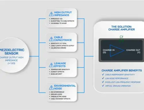
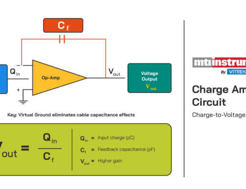
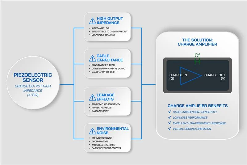
Raw charge signals cannot connect directly to data acquisition systems. The impedance mismatch causes signal loss, noise corruption, and measurement errors that compromise vibration analysis. Charge amplifiers address this issue by converting high-impedance charge into low-impedance voltage, effectively eliminating cable-induced noise and triboelectric effects while providing adjustable sensitivity through selectable gain settings (1, 4, 10 mV/pC).
Key performance parameters that define measurement quality:
- Input capacitance and leakage current determine low-frequency response accuracy. Excessive capacitance causes signal droop that limits the capability to measure slowly varying vibration components, critical for identifying certain failure modes.
- Charge-to-voltage conversion accuracy directly translates to measurement precision across your entire amplitude range. Even a 1% gain error can compound throughout vibration analysis and balancing calculations, leading to inaccuracies.
- Integration options for velocity output allow simultaneous acceleration and velocity measurements from a single sensor. This eliminates post-processing delays and simplifies multi-parameter analysis, providing more efficient data interpretation.
- Noise density and bandwidth define the smallest detectable vibration amplitudes and the highest frequency content that can be captured. A lower noise floor allows early detection of bearing defects, while adequate bandwidth ensures capture of gear mesh and blade pass frequencies.
- Thermal stability is crucial for maintaining calibration validity as test cell temperatures fluctuate. Gain drift due to temperature variations introduces uncertainty, which can compromise critical measurements.
MTI Charge Amplifiers for Precision Vibration Measurement
MTI offers various charge amplifier configurations for installation requirements from portable field measurements to permanent multi-channel test systems.
1. 41CA Dual Channel Portable Charge Amplifiers:
The 41CA delivers dual-channel capability with independent gain and filtering for each channel.
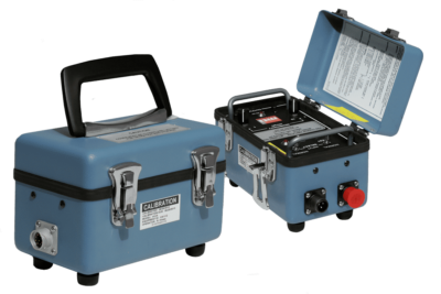
41CA: Dual Channel Rugged Charge Amplifier
2. 55CA Single Channel Charge Amplifiers:
These small, rugged amplifiers can withstand harsh environments, such as engine test cells where reliability cannot be compromised. The 55CA provides single-channel conditioning while the 41CA delivers dual-channel capability with independent gain and filtering for each channel.
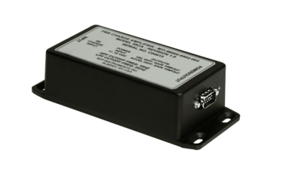
55CA: Single Channel Rugged Charge Amplifier
Features and Technical Capabilities:
- Selectable gains of 1, 4, or 10 mV/pC: These settings accommodate various accelerometer sensitivities without the need for hardware changes. The factory configuration matches your specific sensor specifications and testing requirements, ensuring optimal performance from the moment of installation.
- Differential Input/Output Architecture: This design feature delivers superior noise immunity through common-mode rejection. Galvanic separation prevents ground loops, which can corrupt signals when sensors and DAQ systems operate at different ground potentials– a common challenge in rotating machinery setups.
- Optional Velocity Output: This provides integrated velocity signals alongside acceleration data, both from a single sensor, eliminating the need for additional hardware and simplifiying multi-parameter analysis without complex post-processing.
- Low-Noise Electronics with Extended Temperature Stability: The amplifiers maintain measurement accuracy across thermal cycles. They offer a 20V peak-to-peak linear output voltage with less than 10mV DC offset, providing ample dynamic range for turbine vibration measurements.
Integration considerations:
- DAQ Compatibility: Front-end DAQ systems need appropriate input impedance to properly terminate the amplifier outputs. For typical sensor and cable combinations the input impedance remains below 1kΩ at 1kHz, with capacitance load handling up to 100,000 pF.
- Power Supply Flexibility: The amplifiers can operate on ±15VDC or up to +30VDC, making them suitable for field installations where standard bench power supplies are unavailable. This versatility is especially beneficial in commercial and military aviation applications.
- Shielded Cabling and Proper Grounding: These are essential for achieving the specified noise performance. Highpass filters (0, 10, 15, 20, 25 Hz) remove DC offsets, while lowpass filters (500 Hz, 2k Hz, 5k Hz, 10k Hz) prevent aliasing and ensure clean measurements.
3. CA1800 Rack-Mount Multiple Channel Charge Amplifier:
Laboratory and production balancing systems that require up to eight simultaneous channels benefit from this compact 19-inch rack-mountable solution. Independent gain settings per channel accommodate mixed accelerometer sensitivities in the same system.
Features and technical capabilities:
- Up to Eight Channels of Independent Amplification: This feature allows you to characterize complex machinery or conduct efficient production testing. All input connections are mounted on the rear panel, ensuring clean, permanent installations. Buffered acceleration signals are accessible on the front panel for easy monitoring and access.
- Configurable: The CA1800 houses up to eight 55CA modules, allowing for each channel to isolated and configured independently.
- Integrated Power Supply: The self-contained design includes an internal power supply (110-240 VAC), eliminating the need for separate power distribution in multi-channel installations.
- Complete Operation Guide: The included guide reduces setup time and operator training requirements. The intuitive front panel layout provides clear status indications and signal level monitoring, ensuring quick verification before critical test runs.
Integration considerations:
- Standard Rack-Mount Form Factor: The CA1800 integrates seamlessly into existing 19-inch equipment racks commonly found in test cells and laboratories. This simplifies installation planning and makes equipment upgrades more efficient.
Choosing Between Charge Mode and ICP Accelerometers
Sensor selection depends on your measurement environment, performance requirements, and system constraints. Neither charge nor ICP accelerometers dominate every application, and each has its strengths in different scenarios.
1. Charge Accelerometers
- High-Temperature Applications: Charge accelerometers are the clear choice for high-temperature environments. Turbines, compressors, and jet engines often operate at surface temperatures exceeding 125°C, which can destroy ICP electronics. In these cases, charge-mode accelerometers are the only viable option for accurate vibration measurement.
- Adjustable Gain Flexibility: In research and development (R&D) environments, where multiple test articles are characterized, adjustable gain settings in charge amplifiers allow for easy changes in accelerometer sensitivities. This eliminates the need to replace hardware, reducing both setup time and equipment costs.
- ICP Accelerometers:
- Cost-Sensitive Applications: ICP accelerometers are often preferred in cost-sensitive applications because they eliminate the need for external conditioning hardware. This simplification reduces both component count and system complexity, making ICP sensors ideal for general-purpose vibration monitoring in environments where temperature constraints aren’t a limiting factor.
- Portable and Fixed Installations: ICP accelerometers excel in portable and fixed installations where operating temperatures stay within specified limits. The data acquisition (DAQ) system requires only constant-current sources (typically 2-4 mA) and voltage measurement capability, eliminating the need for external charge amplifiers.
Application Example: Turbine Balancing and Vibration Analysis
MTI’s charge amplifiers provide the essential signal conditioning for precise turbine balancing and vibration analysis, directly influencing balancing accuracy.
- Signal Chain Architecture: A piezoelectric charge accelerometer mounted on the turbine casing generates vibration signals, which are then converted into conditioned voltage by the MTI 55CA Charge Amplifier. This conditioned signal is captured by PBS-4100+, PBS eXpress or DAQ systems for FFT analysis and balancing calculations.
- Stable Amplitude Response: The charge mode accelerometer and amplifier system maintains calibration throughout thermal cycles, ensuring consistent amplitude measurements as the turbine casings heat up from ambient to operating conditions. This stability is crucial for accurate balancing calculations.
- Accurate Phase Response: Balancing algorithms rely on the precise timing of vibration peaks during the rotation cycle to accurately position correction masses. The charge amplifier ensures that phase relationships are maintained, providing the precise timing required for effective balancing.
- Low-Noise Signal Integrity: Clean signals with minimal noise are crucial for sensitive FFT analysis and order tracking, enabling the identification of issues such as bearing defects and blade pass frequencies. Early detection of these issues enables predictive maintenance, reducing downtime and preventing catastrophic failures.
Select MTI Charge Amplifiers for Demanding Measurement Applications
MTI charge amplifiers are ideal for extreme environments, offering low-noise conversion, adjustable gain, and thermal stability for precise vibration measurement. The 55CA and 41CA support field deployments, while the CA1800 is perfect for multi-channel lab installations. For detailed specifications or assistance, visit our website or contact Vitrek’s technical team.