Capacitive vs. Eddy Current Sensors: A Comparison for Non-Contact Measurement
Capacitive vs. Eddy Current Sensors: A Comparison for Non-Contact Measurement
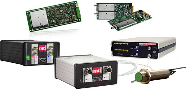
This application note from MTI Instruments compares two widely used types of non-contact sensors: eddy current sensors and capacitive sensors. It covers their basic operating principles, provides a quick comparison, and offers guidance for selecting the right sensor for your application.
Capacitive Sensors: Operating Principles and Applications
Capacitive sensors use electric fields to measure the distance between the sensor face and the target surface. These sensors are particularly effective for measuring conductive and grounded targets, although capacitive proximity sensors can also work with ungrounded materials. The sensing mechanism is designed to ignore nearby surfaces, reducing errors caused by adjacent materials.
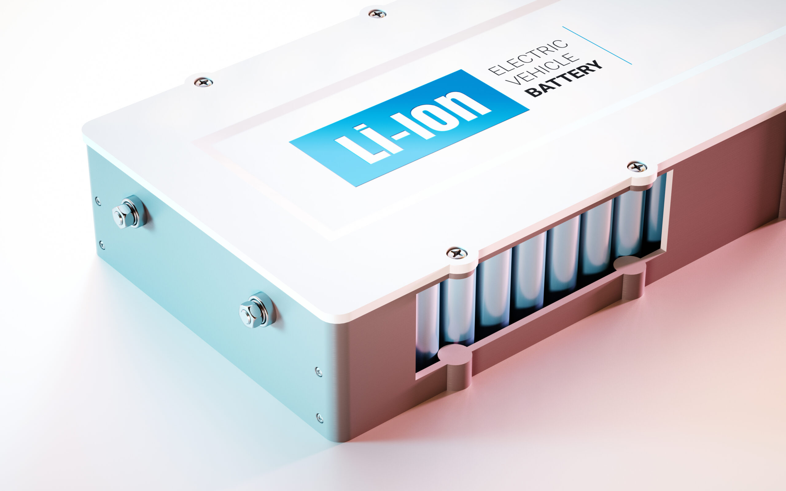
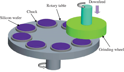
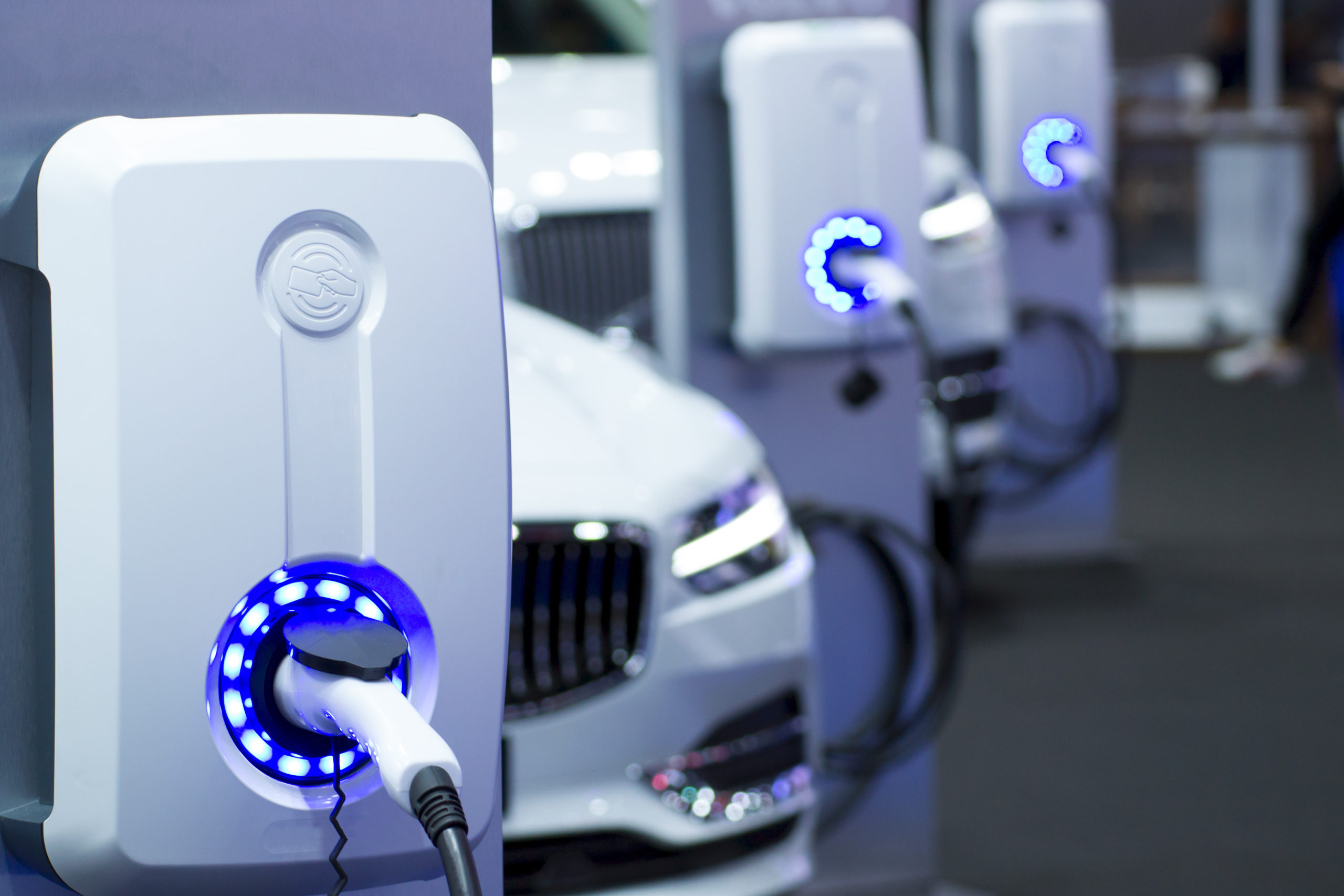
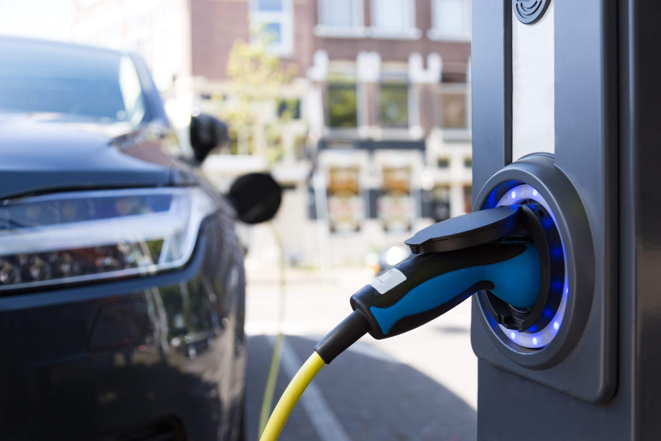
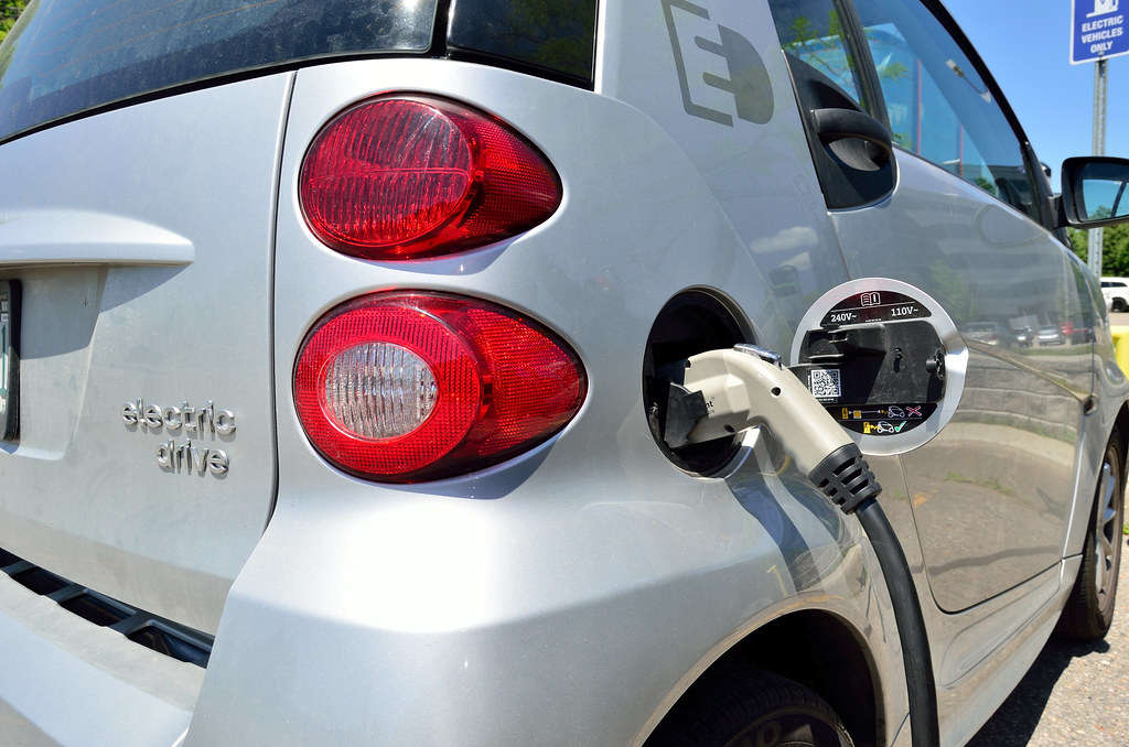
Capacitive sensors are not affected by external factors like temperature, vacuum, air pressure, or magnetic fields. However, the presence of moisture, oil, or dust in the gap between the sensor and the target can lead to inaccurate readings. Capacitive probes are ideal for applications where high precision is needed for thin films, such as measuring the thickness of conductive materials in electric vehicle (EV) battery production.
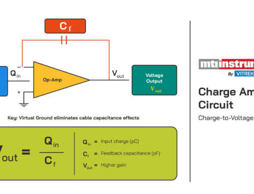
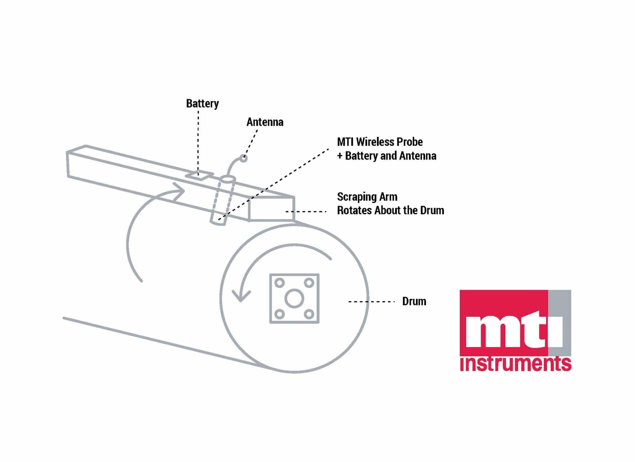
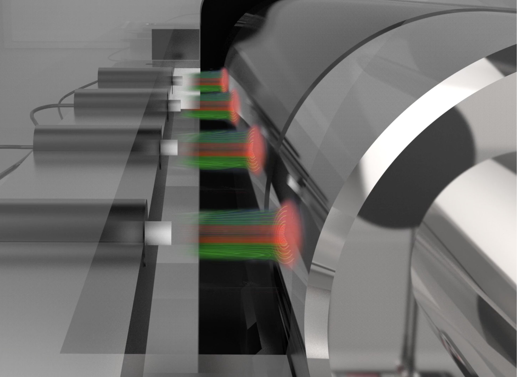
Unlike eddy current probes, capacitive sensors are not influenced by magnetic fields and are best suited for applications requiring high sensitivity to surface features. In applications like the one shown in Figure 3, where the goal is to measure the step height of a thin conductive film, capacitive probes provide the necessary precision.
Advantages of Capacitive Sensors:
- High sensitivity to surface measurements.
- Immune to non-conductive contamination.
- Precise in measuring thin conductive layers.

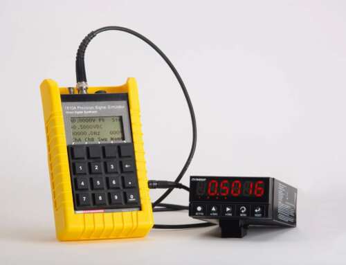
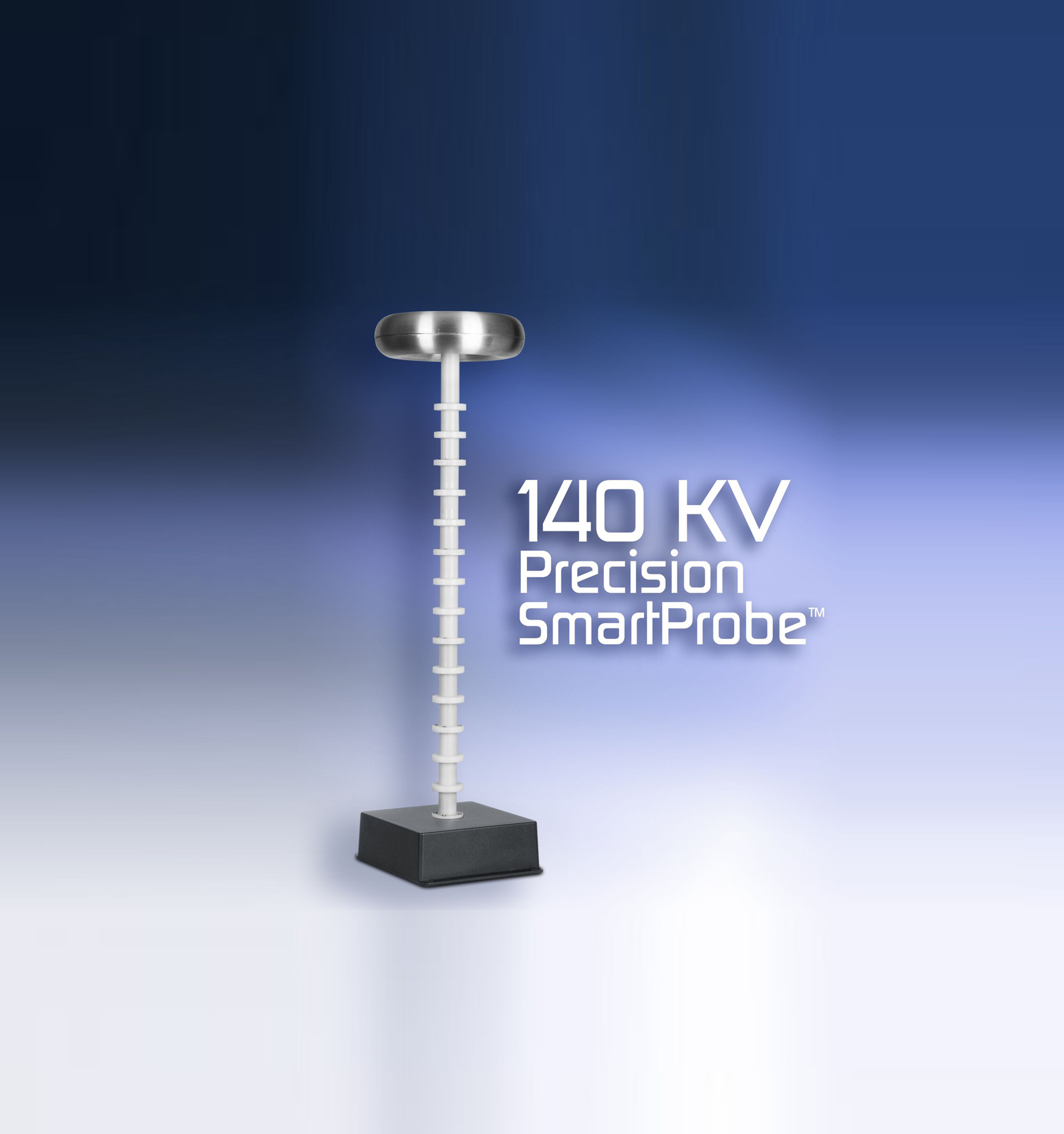
Figure 1: Typical capacitive probe with stainless steel body

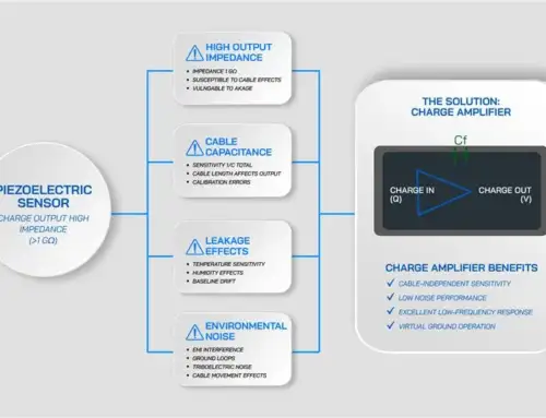
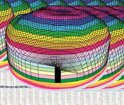
Figure 2: Only the target area under the field is measured

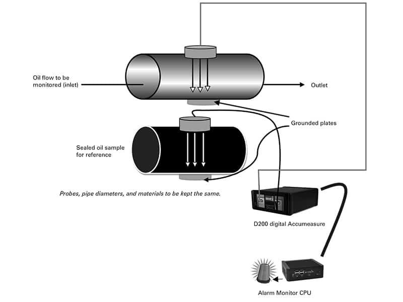
Figure 3: Step height of a thin conductive film on a roller
Eddy Current Sensors: Operating Principles and Applications
Eddy current sensors operate by inducing a magnetic field in the conductive target using an alternating AC current. This generates a back magnetic field proportional to the distance between the sensor and the target. One of the key benefits of eddy current probes is their immunity to contamination from non-magnetic materials, such as oil, dust, or water, which can interfere with capacitive measurements.
However, eddy current sensors have limitations, such as the larger sensing footprint compared to capacitive sensors. These sensors also require recalibration based on the target material. For example, aluminum will require a different calibration factor than steel. Additionally, eddy current proximity sensors may struggle with applications involving rotating targets or thin materials, as the magnetic field may penetrate the surface.

Figure 4: Typical Eddy current probe with plastic face and threaded body

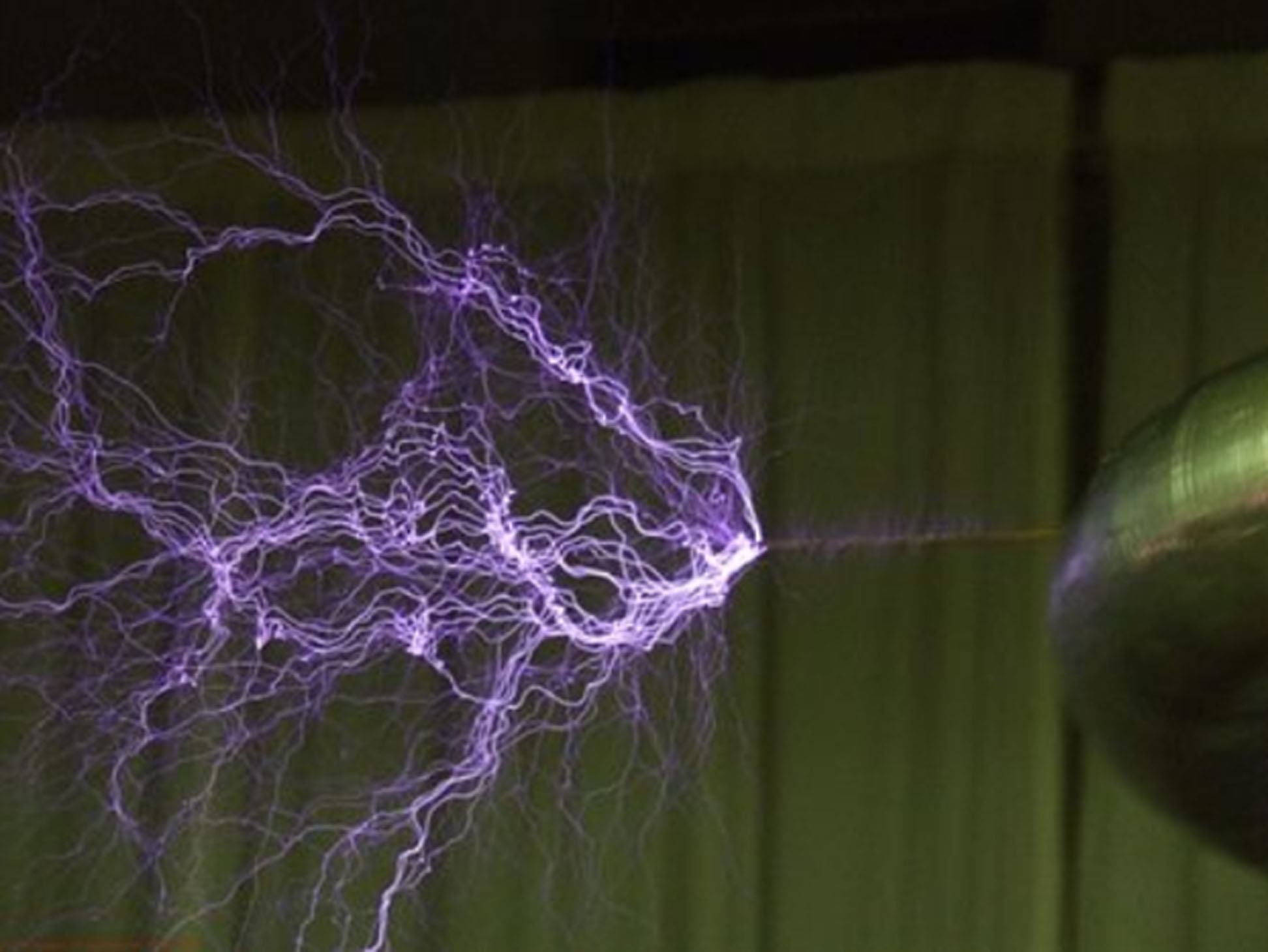
Figure 5: Typical magnetic fields around an Eddy current probe
Advantages of Eddy Current Sensors:
- Not affected by non-conductive contaminants.
- Works well in harsh environments (wet, dusty, etc.).
- Suitable for measuring distances in conductive materials.
Quick Comparison Table
| Factor | Capacitive | Eddy Current |
|---|---|---|
| Dirty Environments (water, oil, grease) | No | Best |
| Small Targets (1x probe diameter) | Good | Poor |
| Large Range (2–3x probe diameter) | Good | Best |
| Thin Materials (< 1mm) | Best | Poor |
| Material Composition (steel, copper, aluminum) | Best | Poor |
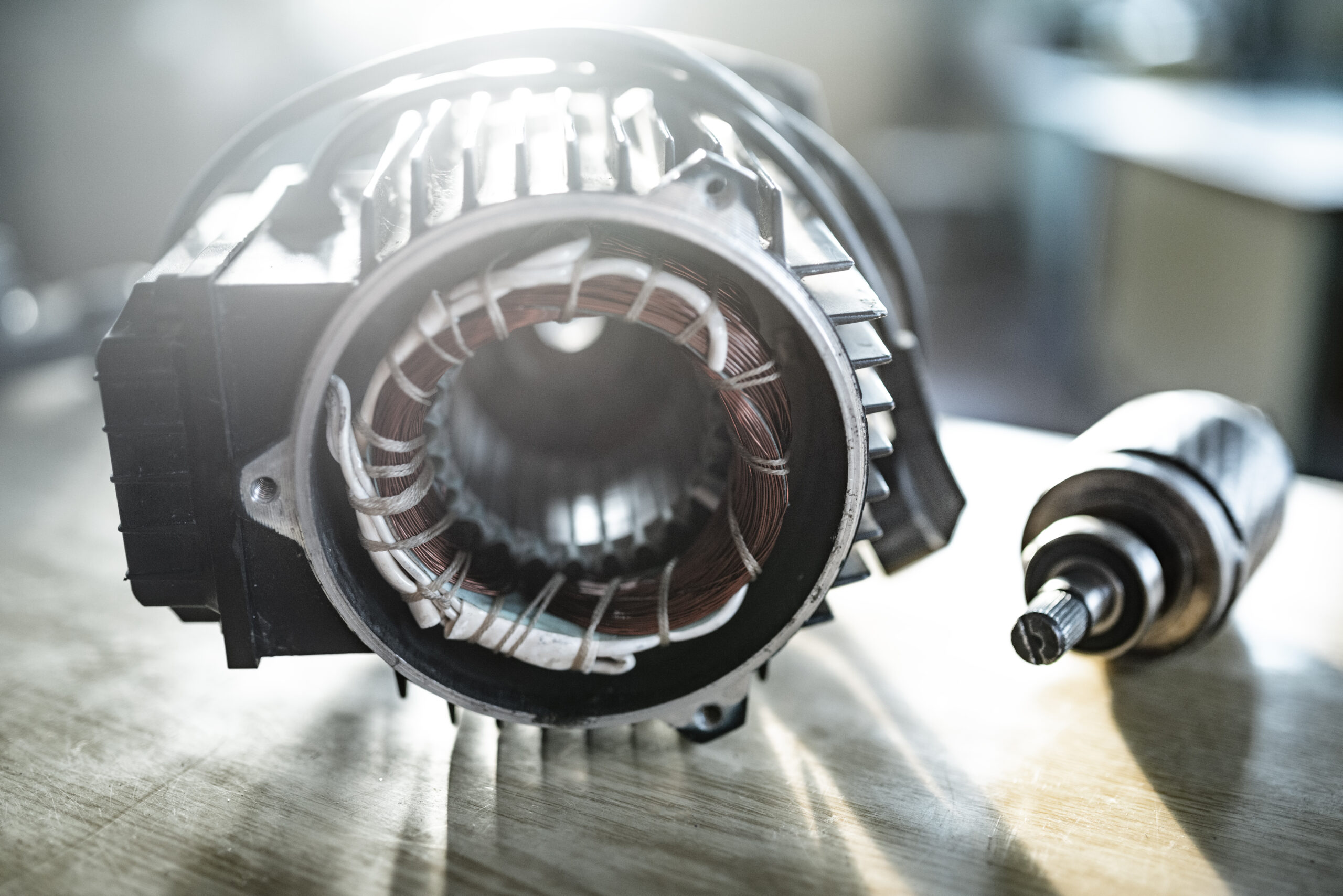
| Laminated Surfaces such as Motor stators | Multiple Probes | Best | Poor |
| Magnetic Field in Sensing Environment | Probe Mounting Ease | Best | OK |
| Resolution (1 x 10⁵ of range) | Best | OK |
| Bandwidth (> 5kHz) | Good | Best |
| Cost | Good | Less Expensive |
Choosing the Right Sensor for Your Application
While capacitive proximity sensors are typically the better choice for applications requiring high sensitivity to thin, flat conductive surfaces, eddy current sensors may be required in challenging environments where contaminants are present. For example, if the measurement area is exposed to oil, water, or dust, an eddy current probe is often the more reliable option.
Before choosing the right sensor, it’s crucial to consider factors like the type of material, target surface characteristics, environmental conditions, and the required level of precision.
MTI Instruments’ Hybrid Probes: Combining the Best of Both Worlds
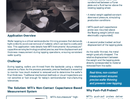
For applications where both types of sensors are needed, MTI Instruments offers a hybrid probe that combines the capabilities of capacitive probes and eddy current probes. This versatile solution is designed to measure the thickness of non-conductive materials on top of grounded metal substrates. It combines the benefits of both technologies, providing accurate measurements in a wide range of industrial settings.
Are you looking for advanced metrology solutions? MTI Instruments provides systems for measuring thickness, total thickness variation (TTV), bow, and warp as part of in-process monitoring or quality control during production. Explore our complete range of eddy current sensor applications to see how we can support your precision measurement needs.


