Testing Charge Amplifier Gain and Frequency Response with a Signal Generator
Description
[Application Note 40518]
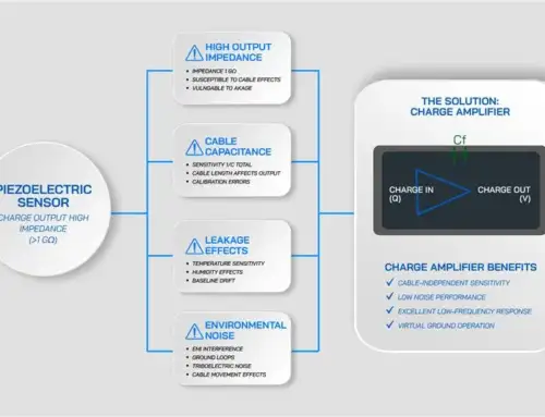
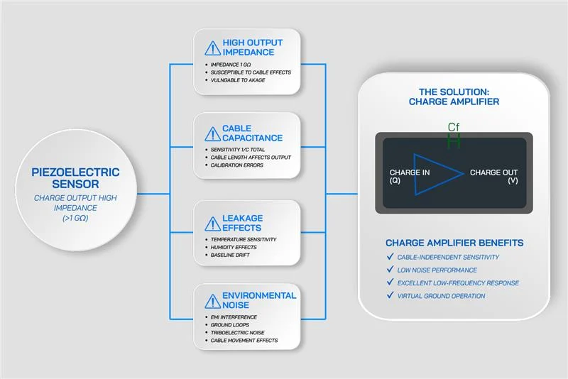
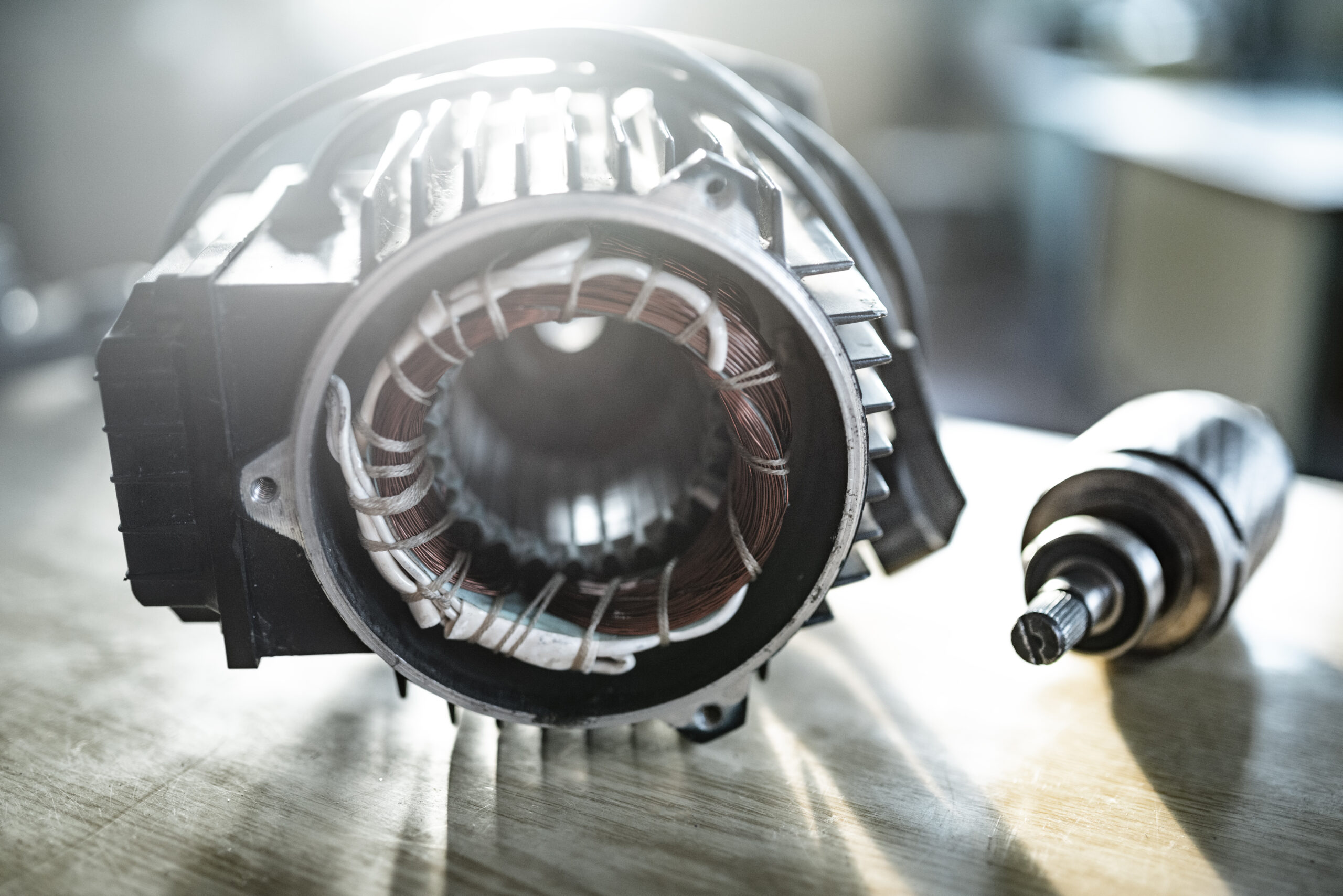
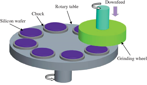
Piezoelectric transducers produce small electrical charges in response to pressure. Their sensitivity, ruggedness, and stability at high temperatures make them an essential building block of many accelerometers and pressure sensors. Applications include turbine vibration measurement (accelerometers) and combustion dynamics monitoring (pressure sensors).
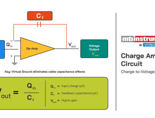
Typically, the high-impedance charge output produced by a piezoelectric transducer must be conditioned and amplified before transmission across system cabling to the data acquisition and measurement instrumentation. This conversion is accomplished with a device called a charge amplifier.
Problem
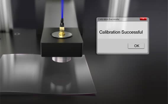
Over time, a charge amplifier’s signal response can drift. Damage to the charge amplifier or associated cabling is also common. Periodic calibration, consequently, is required to ensure accurate measurement of the physical phenomenon exciting a piezoelectric transducer. Many charge amplifiers offer adjustable bandwidth and gain settings that should also be confirmed.
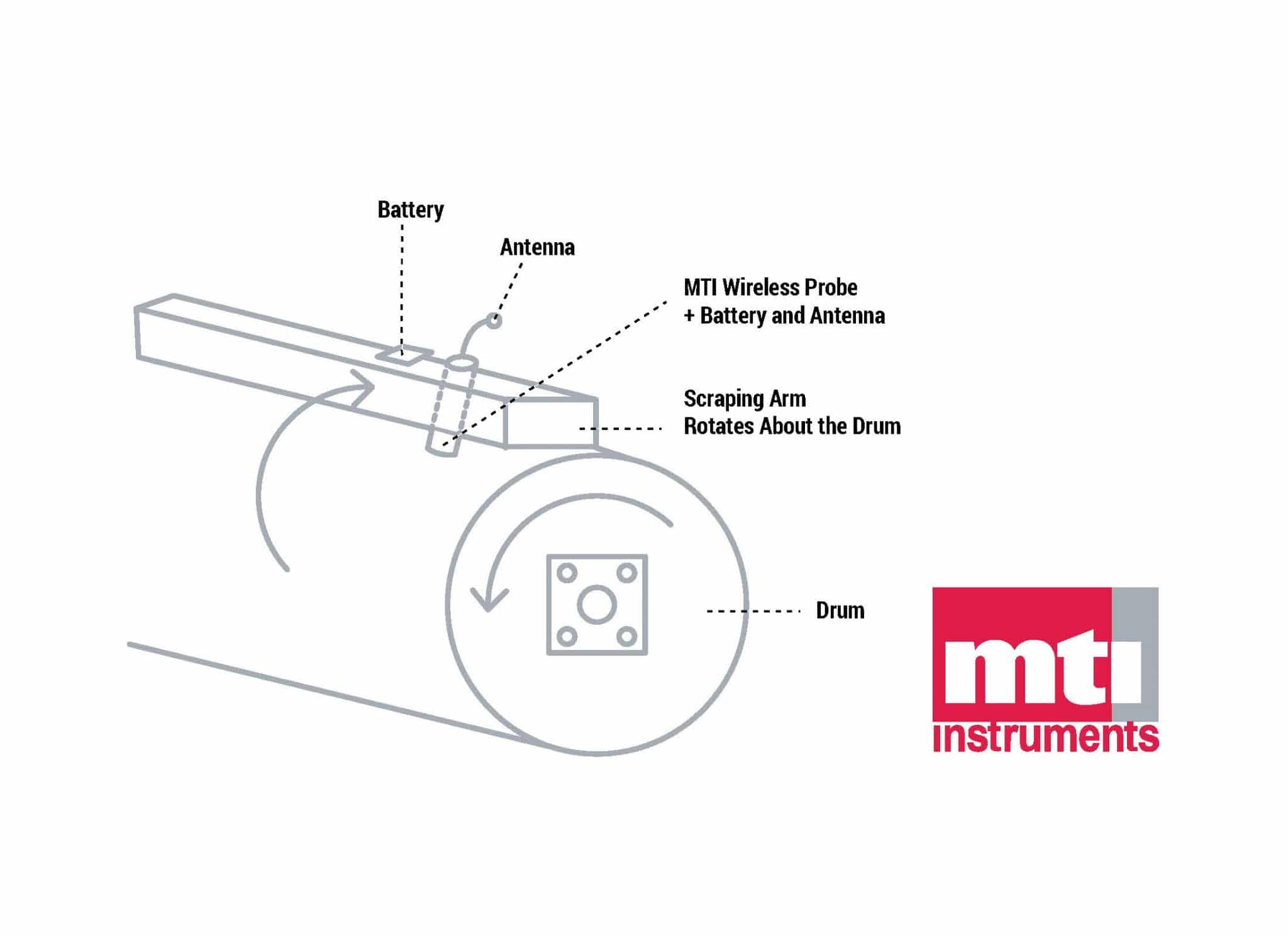
Unfortunately, testing charge amplifier gain and frequency response – as well as system cabling – can be a challenging task. That’s because most signal generators are not equipped with a charge output, and those that are may not have the precision and frequency range necessary to fully test the charge amplifier. Additionally, these types of sensors are typically installed in remote, hostile environments where portable testing equipment is a requirement.
Solution
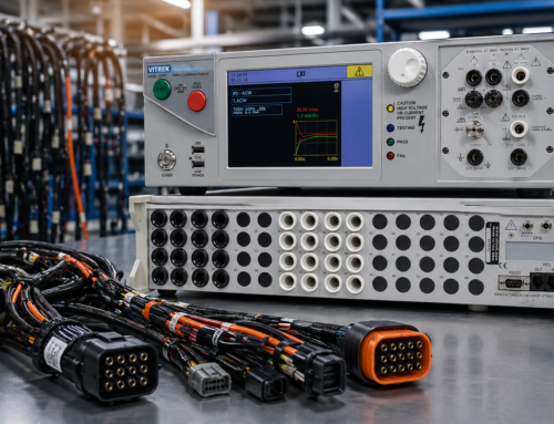
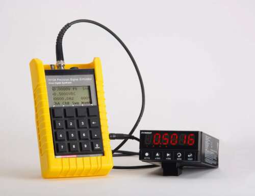
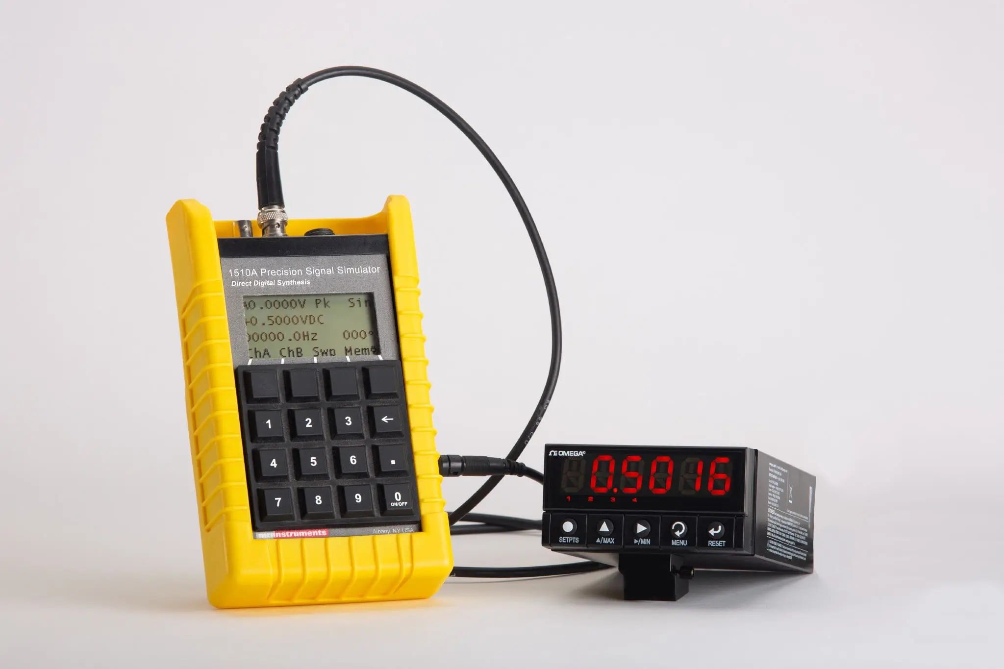
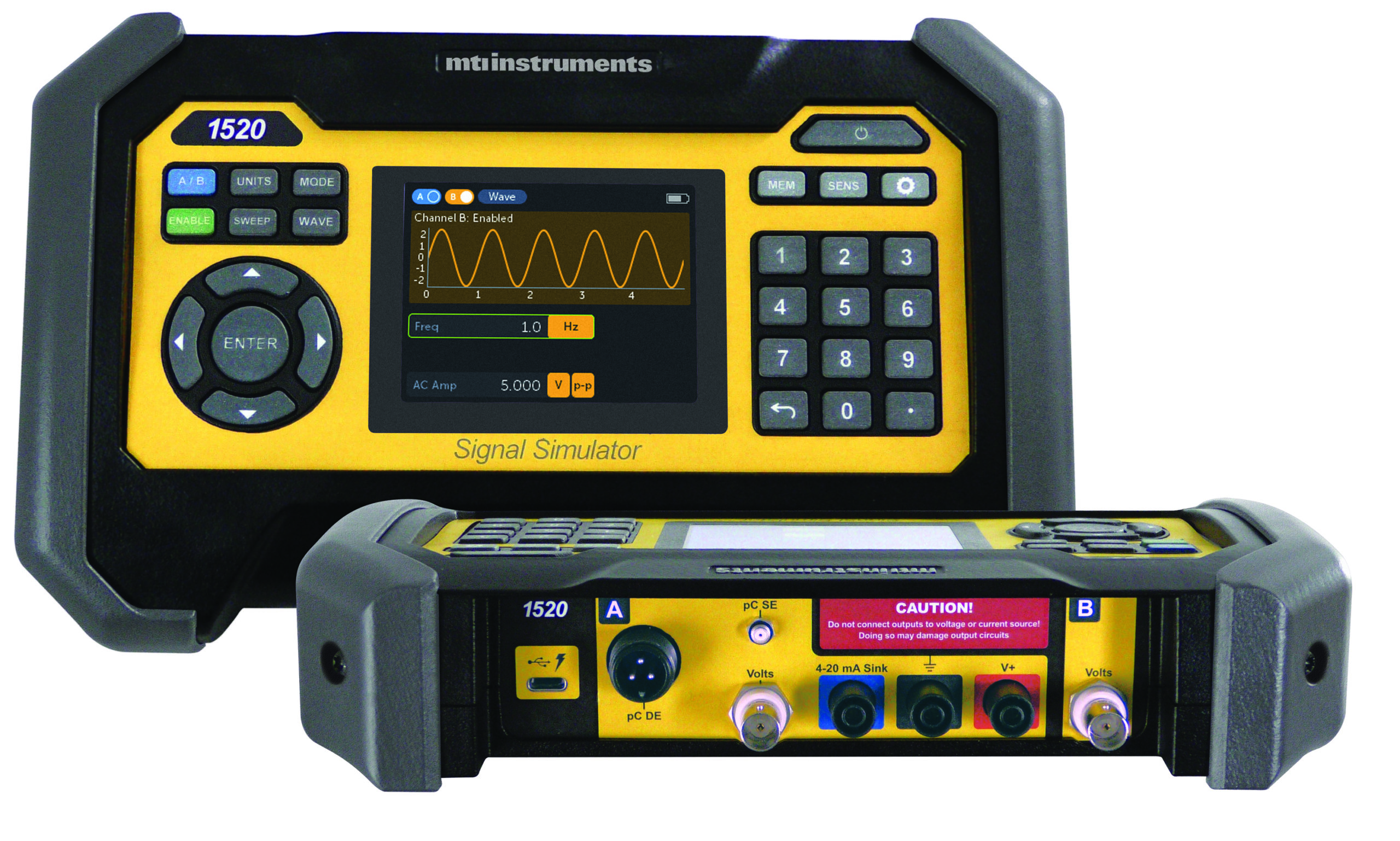
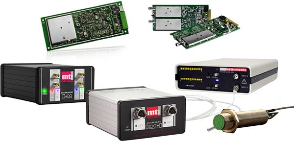
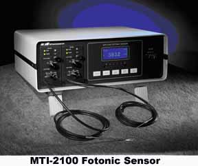
The 1510A Signal Generator from MTI Instruments can simulate most types of piezoelectric transducers for the test and calibration of charge amplifier electronics and associated cabling. Test results using two commercially available products – the Endevco (Meggitt) Model 2777A and the MTI Instruments 55CA – demonstrate its ability to verify frequency response of a typical charge amplifier.

MTI’s 1510A Signal Generator can be used to test the gain and frequency response of a typical charge amplifier. Tests on two
charge amplifiers, the Endevco (Meggitt) Model 2777A and the MTI Instruments 55CA, show both charge amplifiers functioning
as expected.
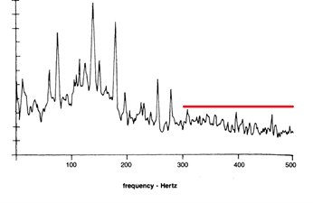
In both instances, the 1510A was used to generate 100 picocoulombs (pC) RMS input signals at various frequencies. An AC voltmeter recorded the RMS voltage outputs. Results show both charge amplifiers functioning as expected.

MTI Instruments 55CA
Specifically, the 2777A datasheet specifies a high-pass -3dB frequency of 8.59 Hz and a low-pass -3dB frequency of 17.5 kHz. The expected gain is 10 mV/pC in the passband. Results matched the expected voltage output: near 70% at 8.59 Hz and 17.5 kHz, and near 100% in the passband.


