Measuring Piezoelectric Properties with Fiber Optics
Description

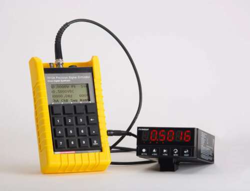
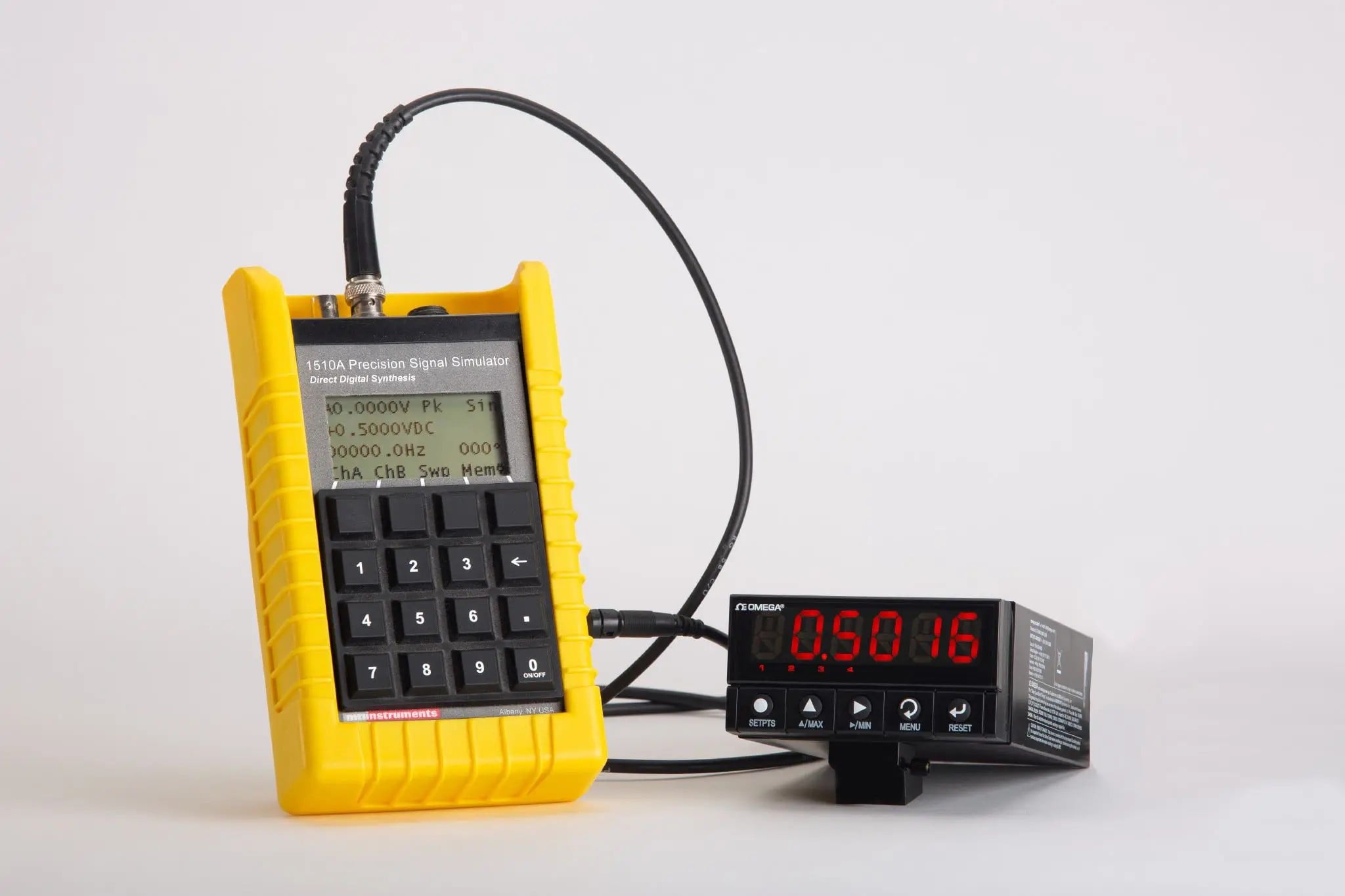
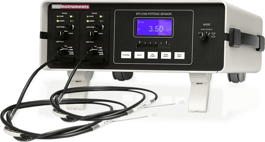
Figure 4: Fiber Optic MTI 2100 Fotonic Sensor
Introduction
Researchers from the University of Arizona used the MTI-2000 Fotonic Sensor to measure the indirect piezoelectric properties (d33) and strain of bulk ferroelectric and thin film samples. The team then correlated these results with data acquired from direct piezoelectric effect measurement. By comparing data sets, the researchers concluded that the MTI-2000 provides a useful optical technique for measuring the d33 values of ceramic thin films such as BaTiOy ZnO and PZT.
The MTI-2000 Fotonic Sensor and 2032RX High Resolution Module are manufactured by MTI Instruments of Lockport, IL. The base unit, the MTI-2000, houses the electronics, communications interfaces, and two bays for removable fiber optic probe modules. Because the probe uses a fiber optic based optical lever to determine the displacement charge, the researchers calibrated the equipment for each sample so that sample-to-sample changes in reflectivity would be eliminated.
Piezoelectric Properties Experiment
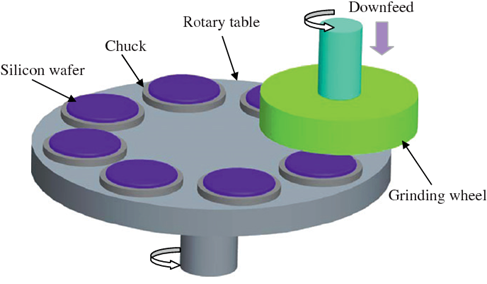
Calibrating the MTI-2000 Fotonic Sensor involves placing the sample under the probe. By adjusting the distance between the fibers in the probe and the sample under test, the researchers found the distance at which the receiving fiber became completely illuminated by reflected light from the neighboring transmitting fiber. This defined the optical peak, the point where the photocell receives the maximum subtended power from a power source.
The MTI-2000 then autocalibrated itself with respect to power source output. This developed a calibration curve for received light power vs. displacement. The front slope of the calibration curve is very steep and has a value of 54.10 Å/mV. It exhibits linear behavior to within ±1% in the middle region so that very small changes in displacement appear as large linear changes in received light.
After calibrating the equipment, the researchers used the MTI 2032RX to increase by a factor of ten the light output and the probe resolution. This produced a front slope resolution of 5.410 Å/mV over a ±1% linear range of approximately 2.25 µm. The resolution limit of the 2032Rx probe is 2.5 Å without external filtering over a frequency range from dc to 150 kHz. Over the same frequency range, external filtering can improve the resolution to 1 Å or less.
By using the MTI-2000 Fotonic Sensor’s analog output, the researchers monitored the voltage output of the probe’s photocell on the screen of a digital oscilloscope. An HP 33120A function generator generated  250 mHz unipolar (+) square wave pulses and a Tektronix 320 digital oscilloscope provided signal acquisition.
When voltage was applied to a sample, the change in displacement was calculated by multiplying the magnitude of the step change in voltage by the probe’s front slope factor (5.410 Å/mV). With the application of a unipolar (+) pulse, the measured displacement was equal to the change in sample thickness. To calculate the piezoelectric coefficient, thickness change was divided by the applied voltage.
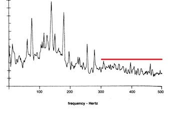
To measure the effect of frequencies on a sample’s piezoelectric properties (d33), the researchers put the MTI-2000 into wide band mode (no low pass filtering) and setup the digital oscilloscope to trigger on the function generator’s bipolar sinusoidal pulse. This allowed the oscilloscope to detect a definitive trigger voltage instead of relying on a seemingly random, noisy signal. Digital averaging removed the background noise from the MTI-2000’s signal and left only the displacement pulse.
Results and Conclusions
In the experiment, the MTI-2000 and 2032RX were used to characterize the piezoelectric properties (d33) of two bulk PZT samples. These samples, labeled 1A and 2B were purchased from Channel Industries, a California-based company that manufacturers piezoelectric materials. Each sample had a proprietary composition and was 38 mm in diameter and 7 mm in thickness. Using a Berlincourt dynamic tester, Channel Industries determined that the d33 for 1A was 554 pm/V and the d33 for 1B was 565 pm/V.
For Sample 2B, the average measured indirect d33 was 570 ±19 pm/V over the applied field range of 1 to 25 V/cm. This matches the Berlincourt measurement. Depending on the applied field, this d33 value corresponds to measured strains from 5 to 85 Å. For verification, the researchers also used a direct piezoelectric effect tester and determined the value was 560 ±17 pC/N.
For Sample 1A, the average indirect d33 was 520 ±8 pm/V, which was well below the 554 pm/V obtained with the Berlincourt tester. This disparity can be explained by the researchers’ electrode configuration. During the 2B and Berlincourt tests, silver electrodes were used to completely covered the samples’ top and bottom faces. During the 1A test, the top electrode was polished and used a mask overlay to deposit 1, 2, 3, and 7 mm Pt electrodes on the sample’s surface.
Regarding the effect of electrode diameter, the results mirror those seen in PZT films, where the measured indirect d33 of a sample depends on the top electrode diameter.
Testing a polyvinylidene fluoride (PVDF) thin film with the MTI-2000 Fotonic Sensor yielded an average measured value of 22 ±170.7 pm/V, which was well within the expected range of 15 to 30 pm/V. The researchers’ direct piezoelectric tests indicated that the d33 was 19±2 pC/N, which compares well with the MTI-2000’s results.
The researchers also showed frequency dependencies of the d33 for sample 1A under an applied field of 7 V/cm for a frequency range of 10 Hz to 60 kHz. This gradual decrease in d33 with an increase in frequency has been reported previously and indicates that the MTI-2000 works properly within this frequency range as proven by the University of Arizona project.


