Interfacing MTI’s Digital Accumeasure to Measurement Computing’s DASYLab with Modbus
Description

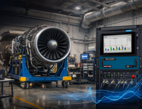
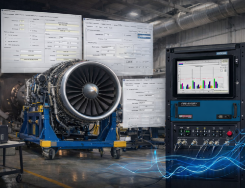
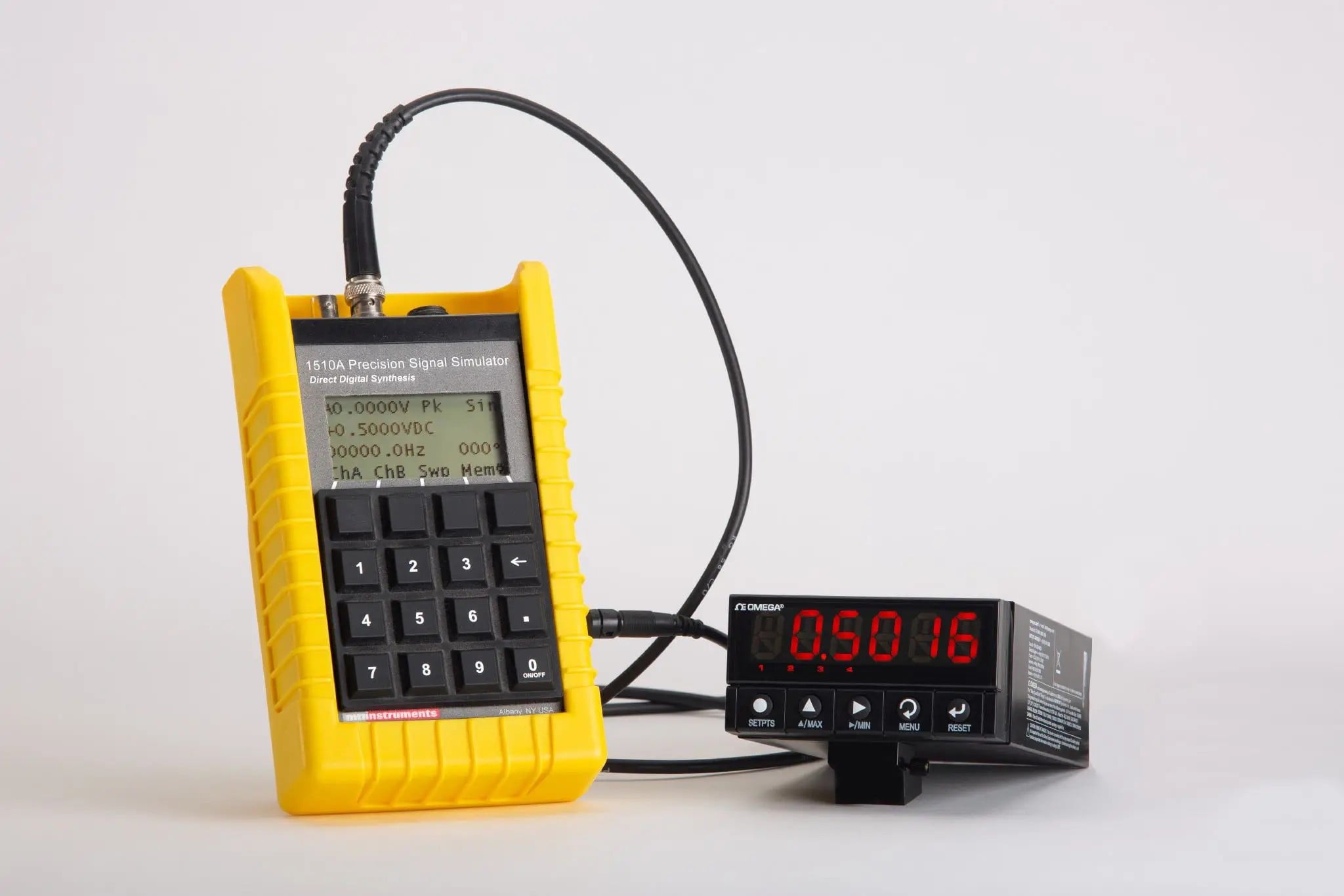
Laptop running MC DASYLab1 © and MTI Digital Capacitance sensor over Modbus TCP/IP
Measurement Computing’s DASYLab data acquisition software is easy to use and allows measuring with multiple system sensors (analog and digital). You can plot the results of multiple sensors versus time or encoder position and store the data with DASYLab.¬†This application note describes how to interface MTI’s Digital Capacitance Sensor over Ethernet TCP/IP. The DASYLab Modbus setup is not difficult to implement but a little tricky the first time you try it. The Modbus interface is very useful and important ¬†as MTI’s Digital Accumeasure2 has 24 bit digital output and the DASYLab Modbus interface allows you to directly import digital displacement values rather than lower resolution analog values. Converting measurement ¬†values back to an analog output (in the Digital Accumeasure ) would actually adds noise and linearity errors to what is already a ¬†highly accurate displacement measurement. We are able to connect DASYLab to the sensor via a Modbus interface. MTI’s Modbus output has 18 registers that can be read. You may only be interested in just a single displacement sensor but you need to read Accumeasure register 32 and the Accumeasure sensor channel corresponding to the input you wish to display in order to have the registers refresh and update correctly. Ordinarily the Digital Accumeasure is set up with a fixed IP address at 192.168.168.247 port 502.
In DASYLab we start by choosing a Modbus analog input module and configuring it to read all the registers shown in Fig 14 as seen below.
Set the input module properties as follows:
- Input is TCP/IP
- Set the address to 192.168.168.247 (port 502 should automatically fill in)
- Turn on inputs 0-7 (by clicking on the input boxes)
Configure each input as follows:
- Device 0
- Register starts at zero checked
- Big Endian checked
- Data type is LONG (signed integer)
- Check swopped word order
For each channel it must be assigned a read register . So for each channel 0-6 you need to fill in the correct register address and the data attributes.
- 0-32
- 1-38
- 2-40
- 3-42
- 4-44
- 5-46
- 6-68
The configuration should look like Fig1.

Fig 14 – Digital Accumeasure Register Map from the manual.

Fig 1 Modbus Input module configuration

Fig 2 is what we would see if we were interested in all the Digital Accumeasure outputs being read, but in this case we just want to read channel 1 input displacement; however we need to enable all 7 inputs to ensure the modbus registers are updated.

Fig 3 is a display of all of the Digital Accumeasure outputs. In this application example we are only interested in reading channel 1  which corresponds to the digital Accumeasure channel 1 output displacement. In this display its shown in tenths of nanometers.

Fig 3 . Minimize the 6 channel meter (meter 00) and add a scaling box and another digital meter (01) . It should appear as above. Set the scaling function module to divide by 10,000 to convert nanometers to um. Label meter 01 as um (micro meters) and you are now reading the digital output from the Digital Accumeasure. You can also wire in a plotter to see the AC wave forms or dynamic signal ¬†plotted against time or even an linear or rotary encoder (reference MTI’s Digital Accumeasure manual to learn how to input a synchronized quadrature encoder).
Notes:
- © 1992-2013 by National Instruments Ireland Resources Limited
- Reference MTI’s Digital Accumeasure user manual for instrument setup and additional Modbus information


