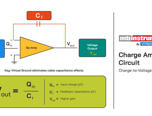
Connecting Encoders to MTI’s Digital Accumeasure
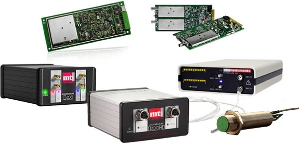
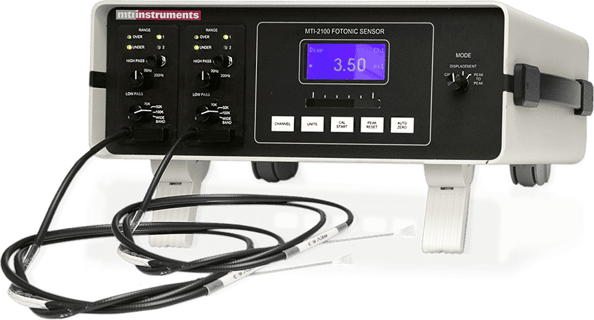
MTI’s Digital Accumeasure D has the ability to accept one or two digital quadrature encoders. The encoders can be linear slide-type or rotary. Digital encoders allow for tracking the position of capacitive probes such that you can synchronize a probe’s position with the probe’s displacement data.
Two common examples are:
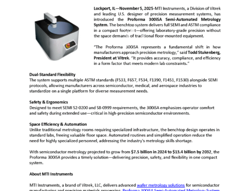
- Rotary shaft runout: shaft (radial) displacement vs. angular encoder position
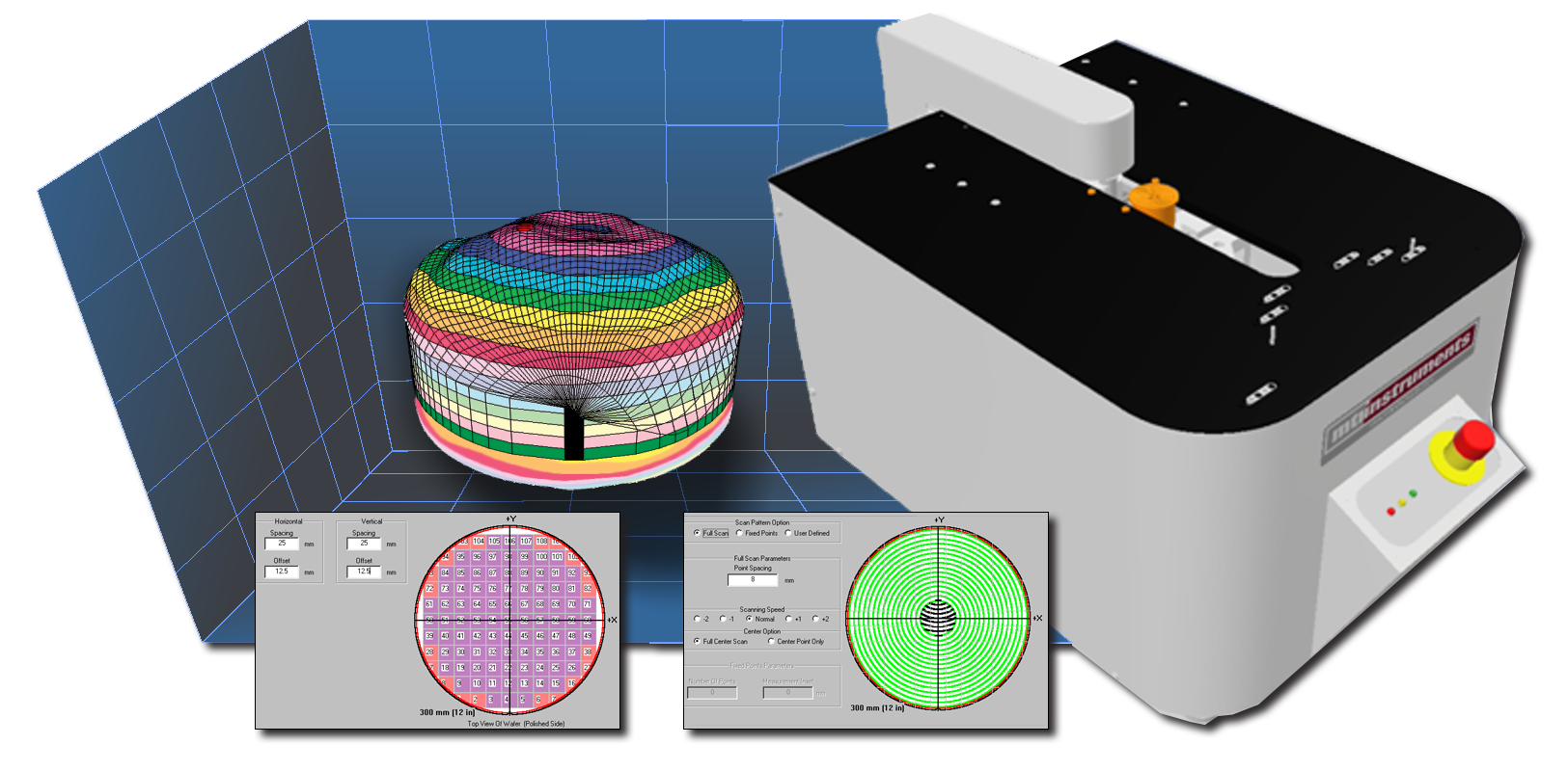
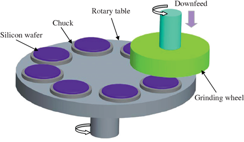
- X/Y position of probes measuring wafer thickness (map wafer thickness)
Accumeasure software (basic and measurement) allows the display of instantaneous encoder counts as well as probe displacement data; however, it doesn’t do much more than that. For example, to create a shaft runout plot, you would need to create an application program (possibly in LabView) that reads the encoder position and synchronized probe displacement data, and then plots the probe displacement data vs. the encoder position on an X/Y plot.
To generate the shaft rotary position (0° to 60° degrees), a rotary encoder is coupled to the rotating shaft. A 1/Rev signal from the rotary encoder is wired to the Q1I. The Q1I signal resets the Digital Accumeasure rotary counter such that the counters count from 0° to 360° then resets. Without the Q1I signal, the Digital Accumeasure counter would continue to count until overflow is reached.
What is a quadrature output?
The Digital Accumeasure accepts quadrature encoder signals, which are commonly called A quad B. Quadrature output refers to the use of two output channels (A and B) separated by 90° of phase shift. The fact that the signals are 90° out-of-phase allows a controller to determine the direction of rotation, (i.e., if channel A leads B, then the encoder is spinning one direction; if B leads A, then it is spinning in the other direction).
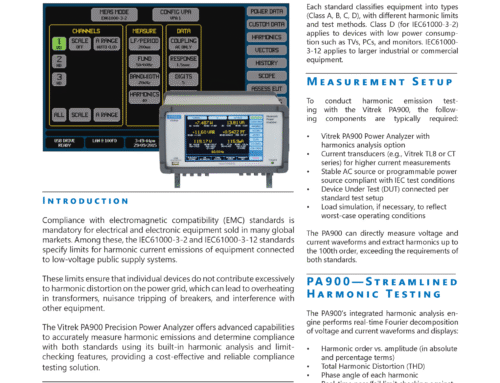
Refer to the channel timing charts for a graphical view (Fig. 1) of this concept. Remember that each channel provides the rated pulses per revolution (PPR) for each encoder. For example, with a 100 PPR encoder, there are 100 pulses per revolution from channel A and 100 pulses from channel B. This is a total of 200 pulses if your controller can count both channels (X2 logic).
Some controllers can count the rising edge and the falling edge of each pulse (on both channels), thereby increasing the effective resolution by a factor of four (X4 logic) and counting 400 edges per revolution on a 100 PPR quadrature encoder. This doesn’t mean that there are 400 pulses coming from a 100 PPR quadrature encoder. The Digital Accumeasure provides X4 logic so that a quadrature encoder rated at 100 PPR will produce 400 counts .

Fig. 1: Channel timing for quadrature outputs
Which encoder outputs do I need?
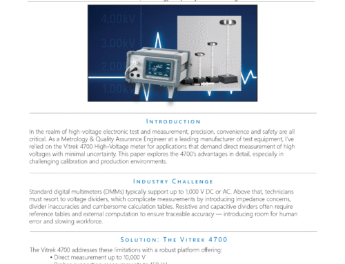
Encoders come with different types of outputs. The easiest to use are TTL or totem pole outputs (Fig 2). Differential outputs can also be used (Fig. 3). With differential outputs, use only one side of the output. It’s fine to use a 5V encoder since the Digital Accumeasure will accept TTL voltage levels (logic 1 = 5V and logic 0 = 0V).
The switching threshold of the encoder inputs is 2V. Make sure you do not have open collector outputs. If you do, you will need to add pull-up resistors (Fig. 4) running from the open collector outputs to the +24VDC supply. Typically, 10K pull-ups would be fine.

Fig. 2: Output pin of encoder to Digital Accumeasure quadrature input

Fig. 3: With differential or line-driver outputs, use only the A phase or B phase output and leave the A/ or B/ (inverted) phase output disconnected.

Fig. 4: Open collector outputs to the +24VDC supply
Using the Z phase , 1/Revolution or N phase signal
Encoders also come with a 1/Revolution output pulse (Fig. 5) that activates once per encoder revolution. When wired to the Digital Accumeasure, this signal will reset the encoder count back to zero as you rotate the encoder past the zero-phase position. The 1/Rev output will be the same as the quadrature outputs: totem pole, TTL, line driver, or open collector .
In the rotary shaft runout example, this would reset the counter at the 0 (zero) phase position. With a linear X/Y encoder, it could be used to reset the encoders when the X/Y stage reached a home position.

Fig. 5: Encoders also come with a 1/Revolution output pulse.
Fig. 6 depicts a complete hookup using an Autonics E4056-360-3-T-24. The encoder is quadrature output, rotary, 24VDC, 360 pulses per revolution, totem pole output with a 1/Rev pulse. Because the Digital Accumeasure is quadrature input, it will actually count 4X 360 PPR or 1440 pulses per revolution and the counters will reset every time the shaft passes through the 0° position. (Click for a larger view.)

Fig. 6: Complete hookup
Additional Notes: Encoder and Trigger Inputs
Accumeasure™ D series products can accept up to two inputs from A quad B type encoders or one input from an A quad B encoder plus an edge trigger. The data from these inputs is sampled at a very high rate, by dedicated hardware, and the status (data) is provided simultaneously with the displacement/thickness readings. As such, the encoders/trigger inputs can be used to provide highly precise positional information that is correlated to the displacement/thickness data from the probes. These inputs accept signals from 5 to 24V peak.
The timing of the encoder inputs are described below:

Fig. 7: Encoder Channel Timing
The encoder inputs are pulled down to ground by 10K ohm resistors. MTI recommends line drive encoders or push-pull type encoder outputs. Open collector or open emitter encoder outputs will require a pull-up or pull-down resistor to operate correctly. Please see the encoder manufacturer’s data sheet. QI is normally tied to the encoder 1/ revolution or Z signal.¬† Additionally, the Digital Accumeasure encoder counters will count four pulses for every one quadrature pulse as the counters advance on the quadrature edge transition.
Note 1 : As the encoder rotates backwards through a count of zero, the counter will move to a saturated, very high count-state since it cannot determine the number of encoder counts per revolution. This can be confusing and should be avoided.
Note 2: If the averaging function is enabled, the encoder counts will also be averaged by the averaging algorithm. This will appear as counter counts that continue to advance (count) even after the encoder stops moving. The counting will stop as the averaging function settles to zero. This could be a period of several seconds.
In Mixed Trigger mode, encoder input Q2I is treated as a general-purpose input pin. The input state is sampled at 20 kHz (synchronous to displacement inputs) and reported as a 0 or 1 in the position channel 2 data stream.
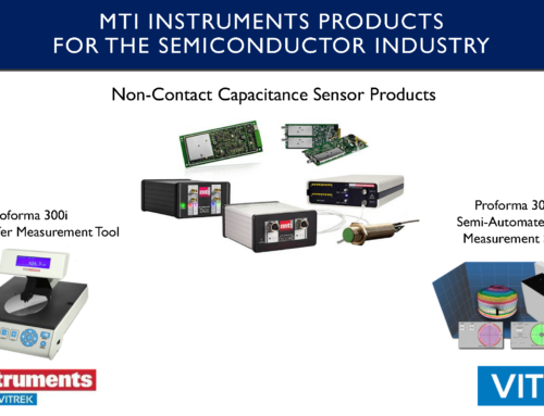
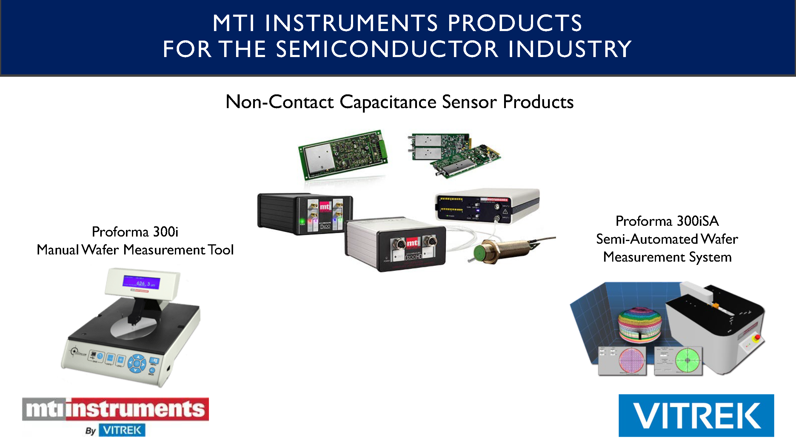
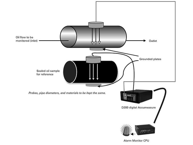
Are you looking for process control metrology products?¬† MTI’s systems can measure thickness, total thickness variation, bow and warp as part of in-process monitoring or as a quality station in production.


