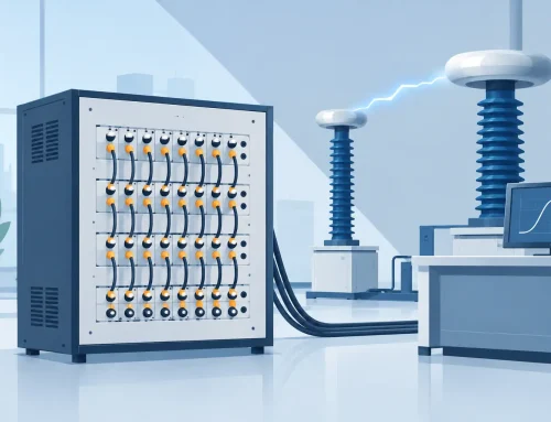
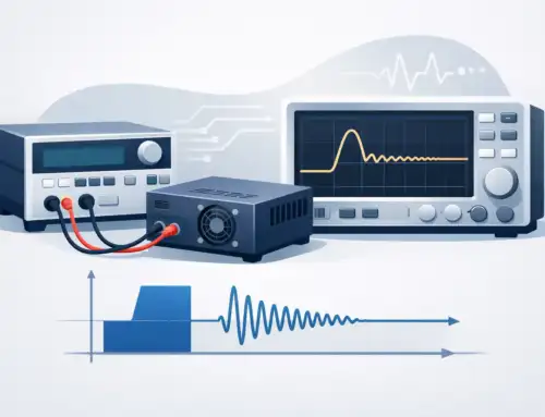
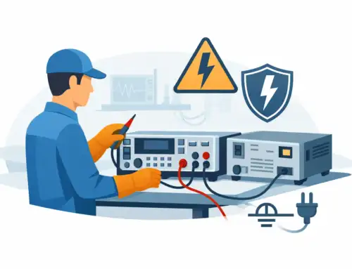
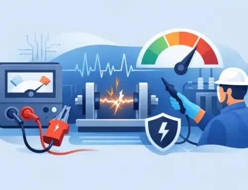
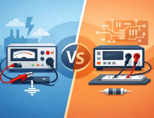
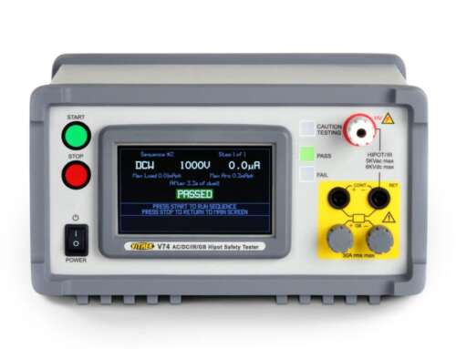
A voltage divider is often drawn as two resistors and a simple equation. In a production test rack, an EV battery measurement fixture, or a high-voltage laboratory system, voltage dividers are more consequential than that schematic suggests. They establish the relationship between an applied potential and the lower-level signal delivered to a digitizer, power analyzer, control circuit, or protective input. If that relationship shifts under voltage, frequency, temperature, or load, the reported measurement shifts with it.
For engineers responsible for safety, validation, or metrology, the relevant question is not merely whether a divider produces the expected nominal ratio. The question is whether it maintains a known, traceable ratio across the operating conditions that matter to the test.
What a Voltage Divider Does
A basic resistive divider places two resistors in series across an input voltage. The output is measured at their junction. If the input voltage is applied across R1 and R2, and the output is taken across R2, the ideal relationship is:
`Vout = Vin x R2 / (R1 + R2)`
This arrangement allows a measurement system with a limited input range to observe a much higher voltage. A 1,000:1 divider, for example, converts a 10 kV input to 10 V at its output. That lower voltage may then be measured by a precision digitizer or data acquisition channel without exposing the instrument input to the full potential.
The same principle appears in far less dramatic applications. Dividers establish reference voltages, scale battery-pack signals for control electronics, sense power-rail voltage, and support feedback loops in power conversion equipment. The application determines whether a general-purpose resistor network is adequate or whether the divider must be treated as a calibrated measurement subsystem.
Why the Ideal Ratio Is Not Enough
The divider equation assumes ideal resistors, zero input current at the measuring instrument, no parasitic capacitance, and a stable source. Real test systems do not meet those assumptions by default.
Resistor tolerance is the first consideration. A pair of 1% resistors may create a ratio that is acceptable for threshold detection but unsuitable for a precision measurement. More importantly, individual tolerance does not fully describe ratio accuracy. The temperature coefficients of the two resistors, their voltage coefficients, long-term stability, and tracking behavior all affect the ratio over time.
Input loading is another common source of error. The instrument connected to the divider output effectively becomes part of the lower leg of the network. If a divider has a high output resistance and the instrument input impedance is not sufficiently high, the measured output falls below the calculated value. An oscilloscope probe, digitizer channel, relay matrix, or protection circuit can each change the effective load.
For a simple example, consider a divider with a 9 megohm upper resistor and a 1 megohm lower resistor. Ideally, it produces one-tenth of the input voltage. Connecting a 10 megohm instrument input in parallel with the 1 megohm lower resistor changes the effective lower resistance to about 909 kilohms. The divider ratio no longer equals 10:1. That error may be material even before temperature or frequency effects are considered.
Resistance, Leakage, and High-Voltage Behavior
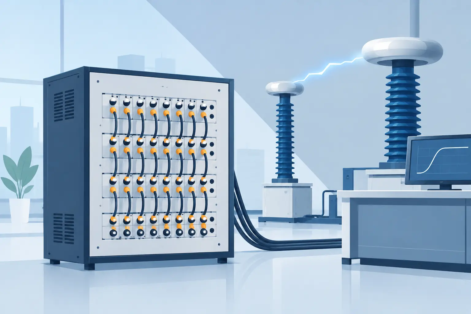
High-voltage measurement increases the importance of physical construction. At elevated potentials, the PCB surface, insulation materials, connector system, and surrounding environment can introduce leakage paths that are comparable to the current flowing through a high-resistance divider.
Humidity, contamination, flux residue, and degraded insulation can create errors that do not appear during a quick bench check. Guarding techniques, appropriate creepage and clearance distances, clean insulating surfaces, and carefully selected resistor bodies help control these effects. The required approach depends on the voltage level, expected environment, applicable safety standard, and uncertainty target.
Resistor voltage coefficient also deserves attention. Some resistor technologies change resistance as the voltage across the element rises. In a high-ratio divider, the upper leg may carry most of the applied voltage, so even a small voltage-dependent resistance change can affect the ratio. Distributing voltage across a properly designed series string can improve voltage handling and reduce stress on individual elements, but it also introduces more nodes where parasitic capacitance and leakage must be controlled.
Power dissipation is equally practical. Divider current is set by the total resistance. Higher resistance reduces dissipation and source loading, yet makes the network more sensitive to leakage and input loading. Lower resistance improves immunity to those effects but increases heat and may exceed the source capability. There is no universally correct resistance value. The appropriate design balances thermal behavior, bandwidth, loading, safety margin, and the intended measurement uncertainty.
Frequency Response Changes the Divider
A resistive divider may behave predictably at DC and still produce unacceptable error on a fast transient. Every physical implementation includes capacitance between resistor elements, from the high-voltage node to ground, and at the output connection. At higher frequencies, those capacitances alter the impedance of each leg and therefore alter the division ratio.
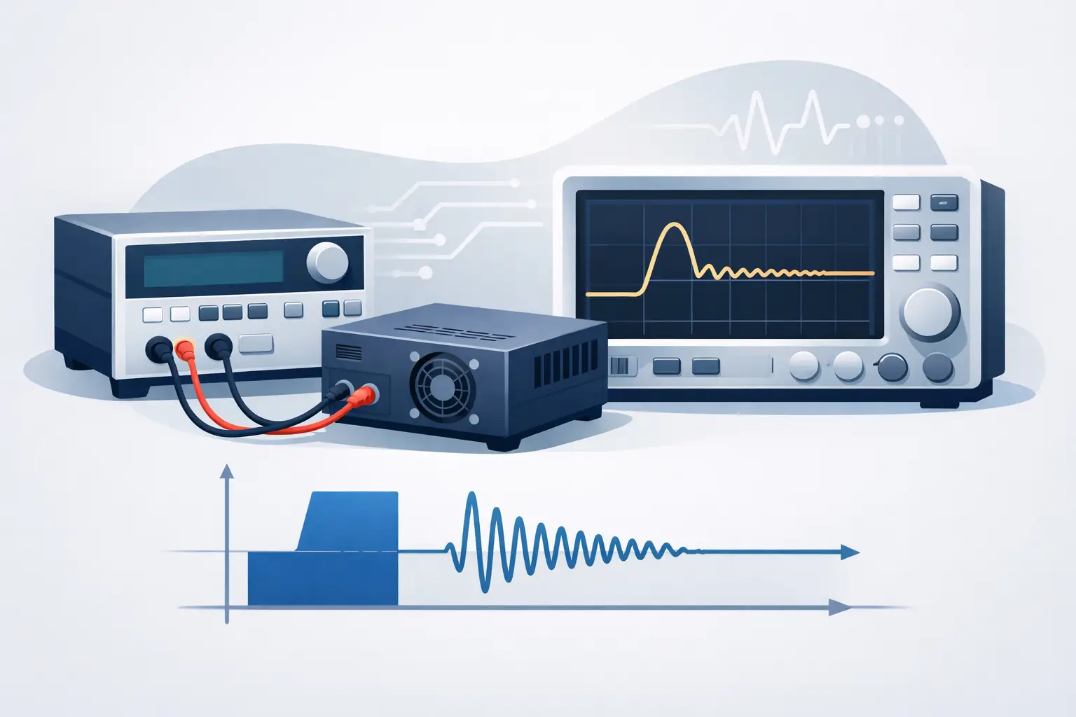
This is why a divider intended for switching waveforms, inverter output, partial-discharge-related events, or impulse testing must be evaluated as a frequency-dependent network. A DC calibration alone cannot establish performance for a waveform with fast edges.
Capacitive dividers use capacitors rather than resistors to set the ratio. Their division ratio is determined by capacitance values and can be advantageous for AC or impulse measurements because they dissipate little power. However, they do not measure DC, and their accuracy depends on capacitor stability, dielectric properties, layout, connections, and the input capacitance of the instrument.
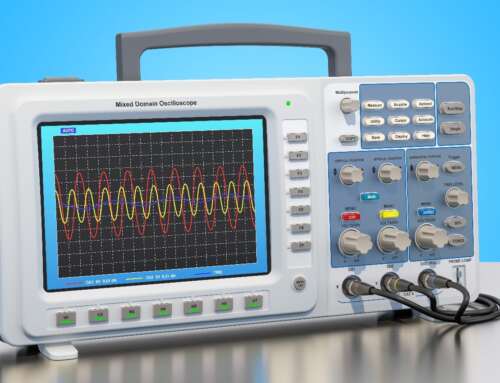
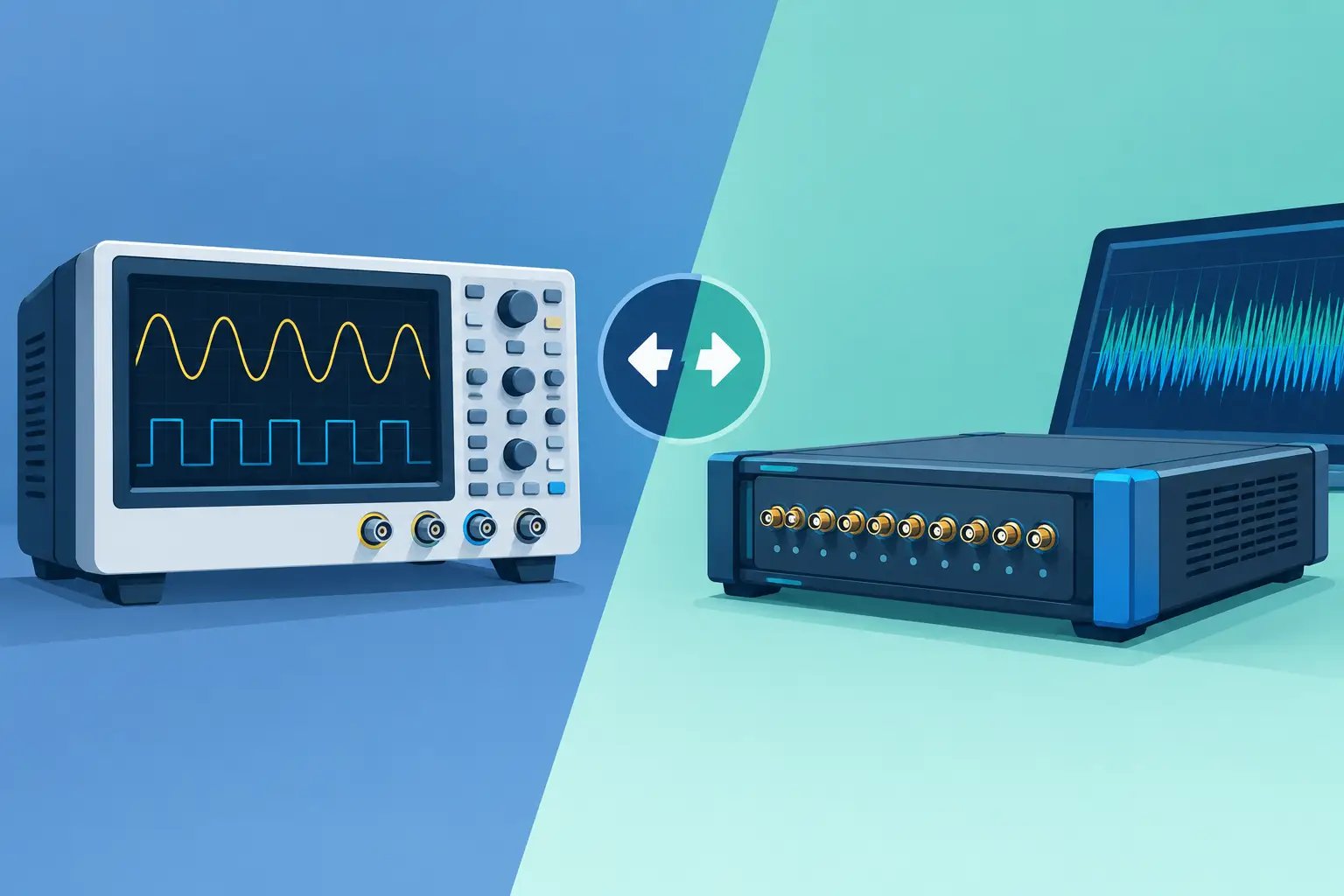
Compensated dividers combine resistance and capacitance to maintain a consistent ratio over a specified bandwidth. The familiar 10:1 oscilloscope probe is a practical example: its resistive ratio is paired with adjustable capacitance to match the oscilloscope input. Industrial measurement systems apply the same principle on a larger scale, often with tighter requirements for amplitude accuracy, settling time, and isolation.
Selecting a Divider for the Measurement Task
The divider should be specified from the measurement requirement backward, not selected only from the maximum voltage. Start with the highest continuous voltage, anticipated transients, source impedance, required bandwidth, and allowable uncertainty. Then assess how the divider will interact with the instrument that follows it.
For low-frequency or DC measurement, ratio accuracy, temperature coefficient, voltage coefficient, insulation resistance, and settling time are usually central. For power electronics and switching measurements, frequency response, common-mode behavior, pulse response, and shielding become equally important. For compliance-oriented testing, operator safety, rated insulation, interlock strategy, and documented calibration status may carry as much weight as nominal ratio.
A useful specification review addresses at least these four areas:
- Voltage capability: continuous rating, transient withstand, insulation coordination, and safe physical integration.
- Ratio performance: initial ratio error, temperature stability, voltage dependence, and long-term drift.
- Dynamic response: bandwidth, rise-time behavior, overshoot, settling, and sensitivity to cable and instrument capacitance.
- System integration: output impedance, instrument input characteristics, grounding arrangement, connectors, shielding, and calibration method.
These factors are interconnected. A high input impedance may minimize loading but can increase sensitivity to environmental leakage. A short, low-capacitance cable may support bandwidth but may not provide the needed physical separation in a high-voltage fixture. The best choice depends on which errors have the greatest effect on the final test decision.
Calibration Must Reflect the Installed System
A divider can be accurate on its own and inaccurate after installation. The measurement chain includes the voltage source, divider, cabling, switching, acquisition input, software scaling, and grounding configuration. Calibration or verification should therefore be performed as close as practical to the actual test configuration.
For ratio measurements, compare the scaled output to a known reference input over the relevant voltage range. Where waveform performance matters, verify the response using representative frequencies or pulse conditions. Record the instrument range, cable configuration, divider orientation if applicable, environmental conditions, and the uncertainty of the reference standard. Those details support repeatability and make later troubleshooting more efficient.
Periodic calibration is not simply an administrative requirement. It provides evidence that resistor drift, insulation degradation, connector contamination, or handling damage has not changed the measurement relationship. In regulated manufacturing and mission-critical development, that evidence can be as valuable as the reading itself.
Grounding and Safety Are Part of Measurement Integrity
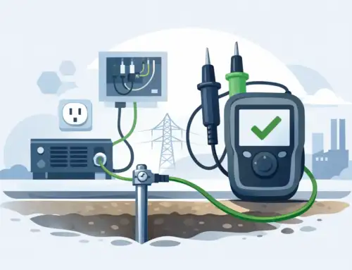
A voltage divider connected to high energy or high common-mode voltage requires a defined grounding strategy. Ground loops can introduce noise and measurement offsets. An incorrectly grounded instrument can create a hazardous condition or bypass intended isolation. Before connecting a divider to a grounded measurement input, confirm the allowable common-mode voltage, terminal-to-ground ratings, source reference, and fault-energy characteristics.
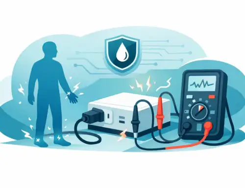
Where personnel may access fixtures, use appropriately rated enclosures, barriers, interlocks, discharge paths, and procedures. A divider can retain charge in distributed capacitance after the source is removed, particularly in high-voltage systems. Safe discharge and verification practices should be designed into the test process rather than left to operator judgment.
For demanding voltage measurement, treat the divider as an engineered interface between the device under test and the instrument. When its ratio, loading, bandwidth, insulation, and calibration are aligned with the application, the data downstream has a defensible foundation.