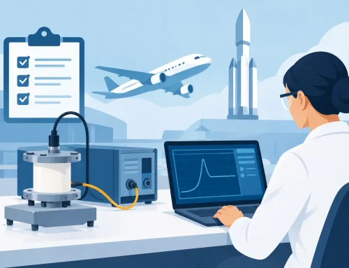
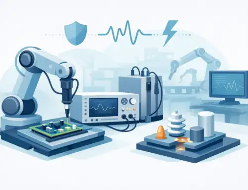
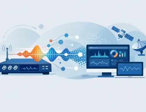
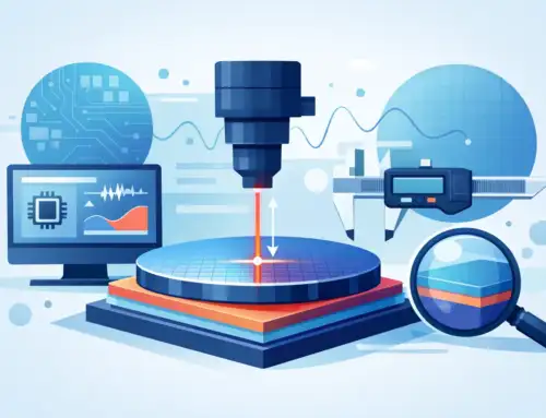
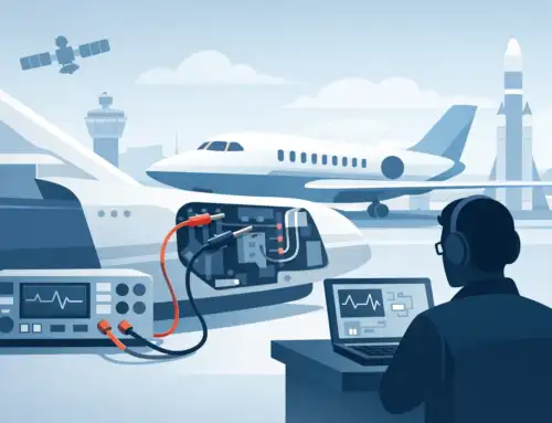
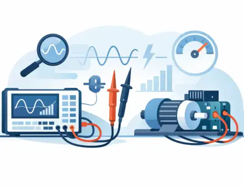
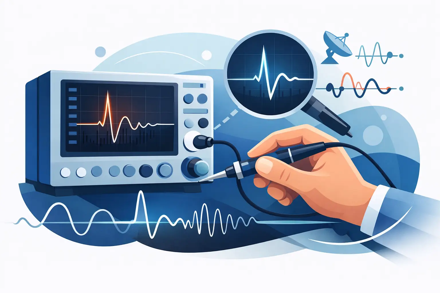
A missed transient during a flight-test event cannot be recreated by rerunning the data file. Aerospace data recorders exist to capture the electrical, physical, and RF evidence behind an event as it occurs – whether that event is a control-system anomaly, a power disturbance, an engine vibration condition, or an intermittent communications issue. Their value is not simply storing data. It is preserving signal integrity, timing context, and traceability so engineers can make defensible technical decisions.
For aerospace and defense programs, the recorder is often part of a larger measurement chain that includes sensors, signal conditioning, digitizers, telemetry equipment, time sources, and analysis software. A weakness at any point in that chain can undermine the usefulness of the final record. Selecting the right platform therefore requires more than comparing channel count and sample rate.
What Aerospace Data Recorders Must Capture
The term aerospace data recorder can refer to several different systems. Flight data and cockpit voice recorders are designed primarily for accident investigation and operational monitoring. Flight-test and development recorders, by contrast, are measurement systems used to capture engineering data during development, qualification, production test, maintenance, and diagnostics.
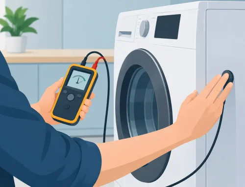
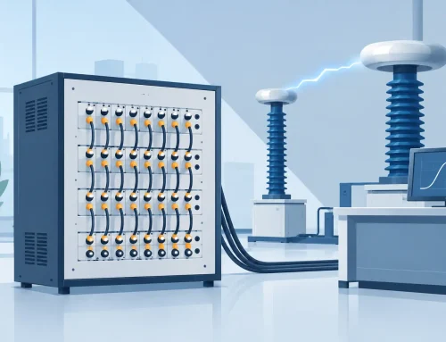
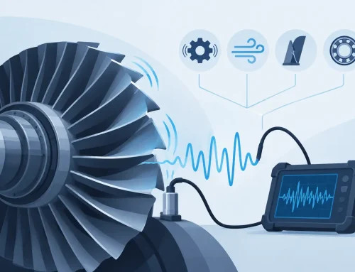
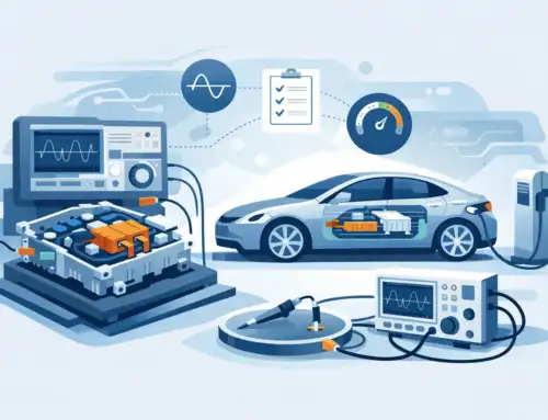
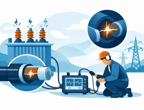
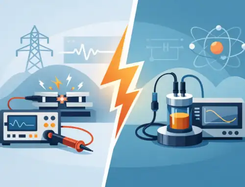
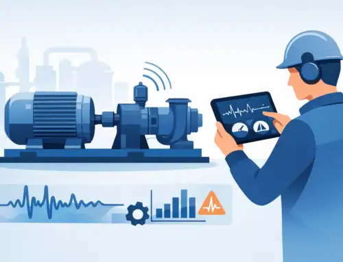
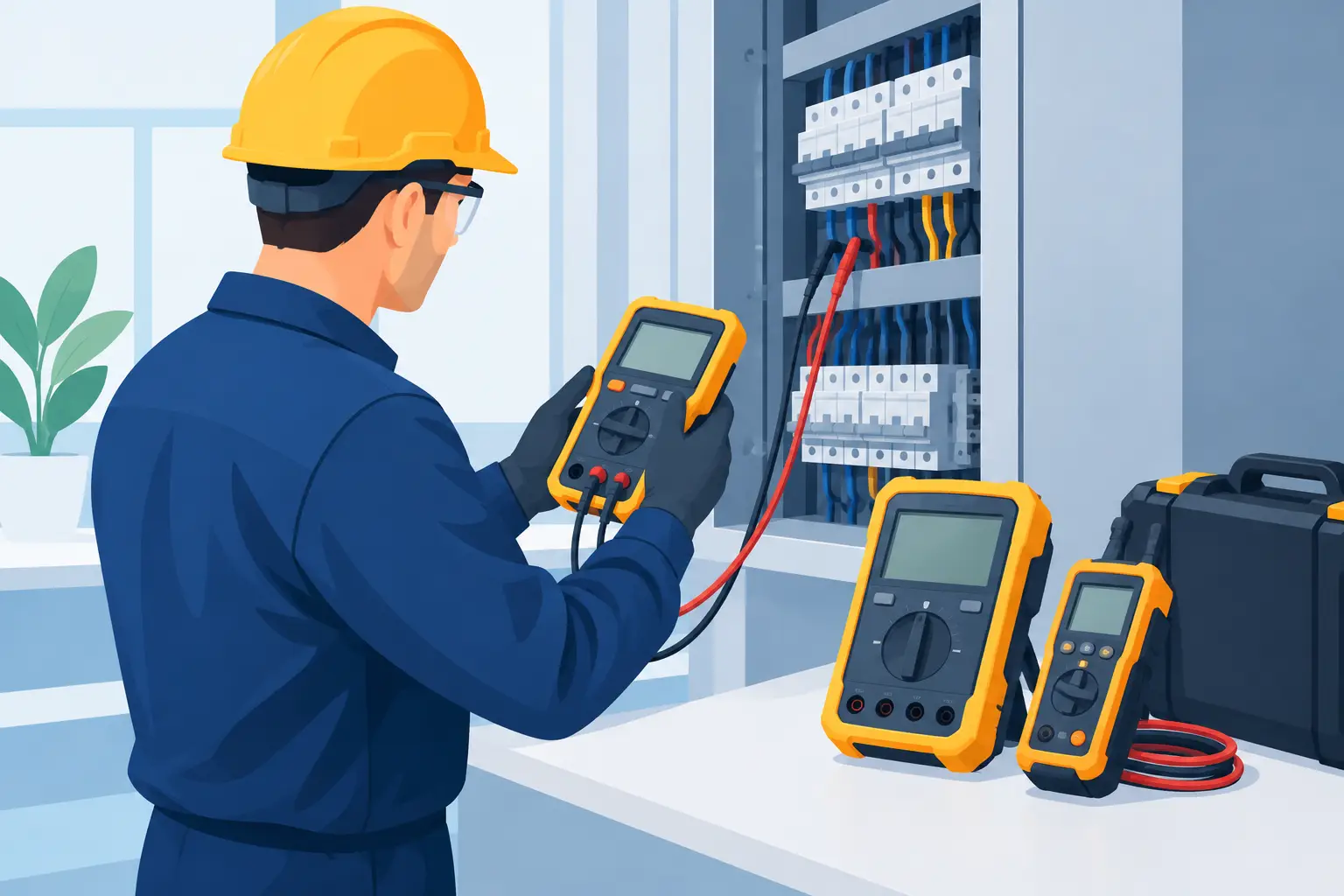
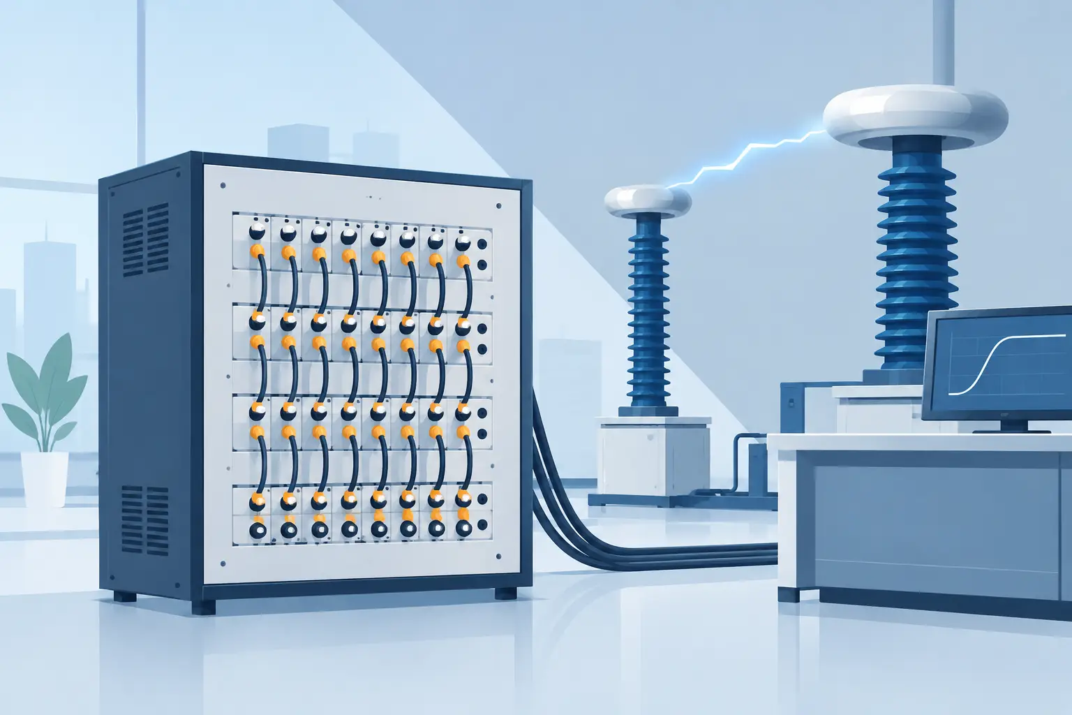
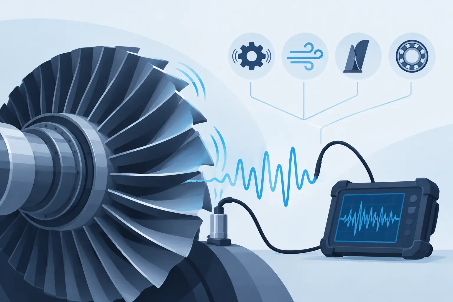
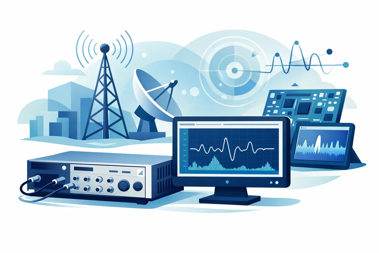
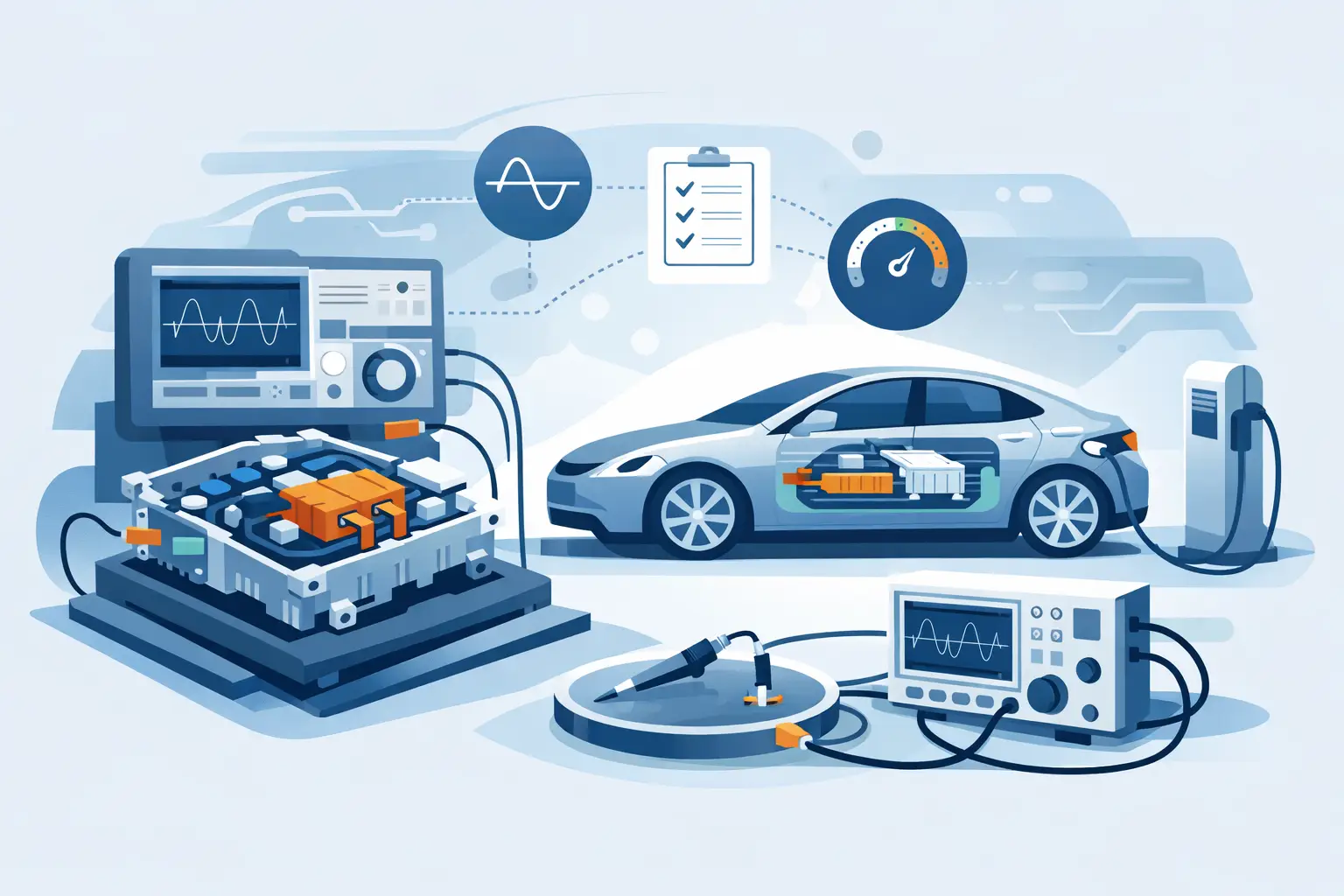
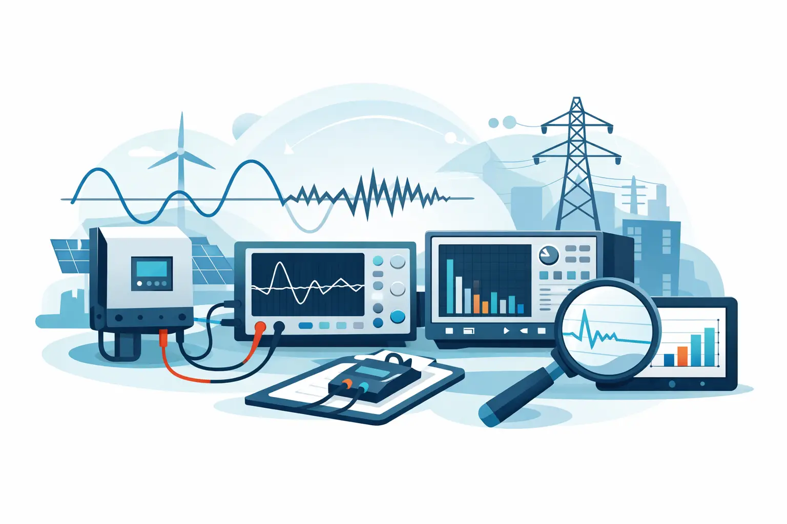
An engineering recorder may acquire analog voltage, strain-gage, accelerometer, thermocouple, current, pressure, discrete, bus, RF, or IF signals. In ground test, it may record high-voltage switching behavior, transient current, vibration, or control-loop response. In airborne test, the same system may need to operate under tighter size, weight, power, thermal, and environmental constraints.
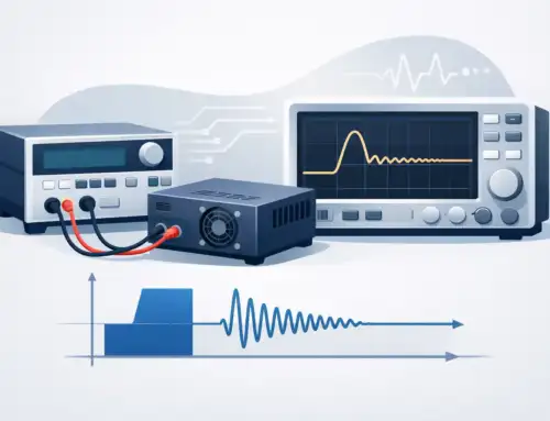
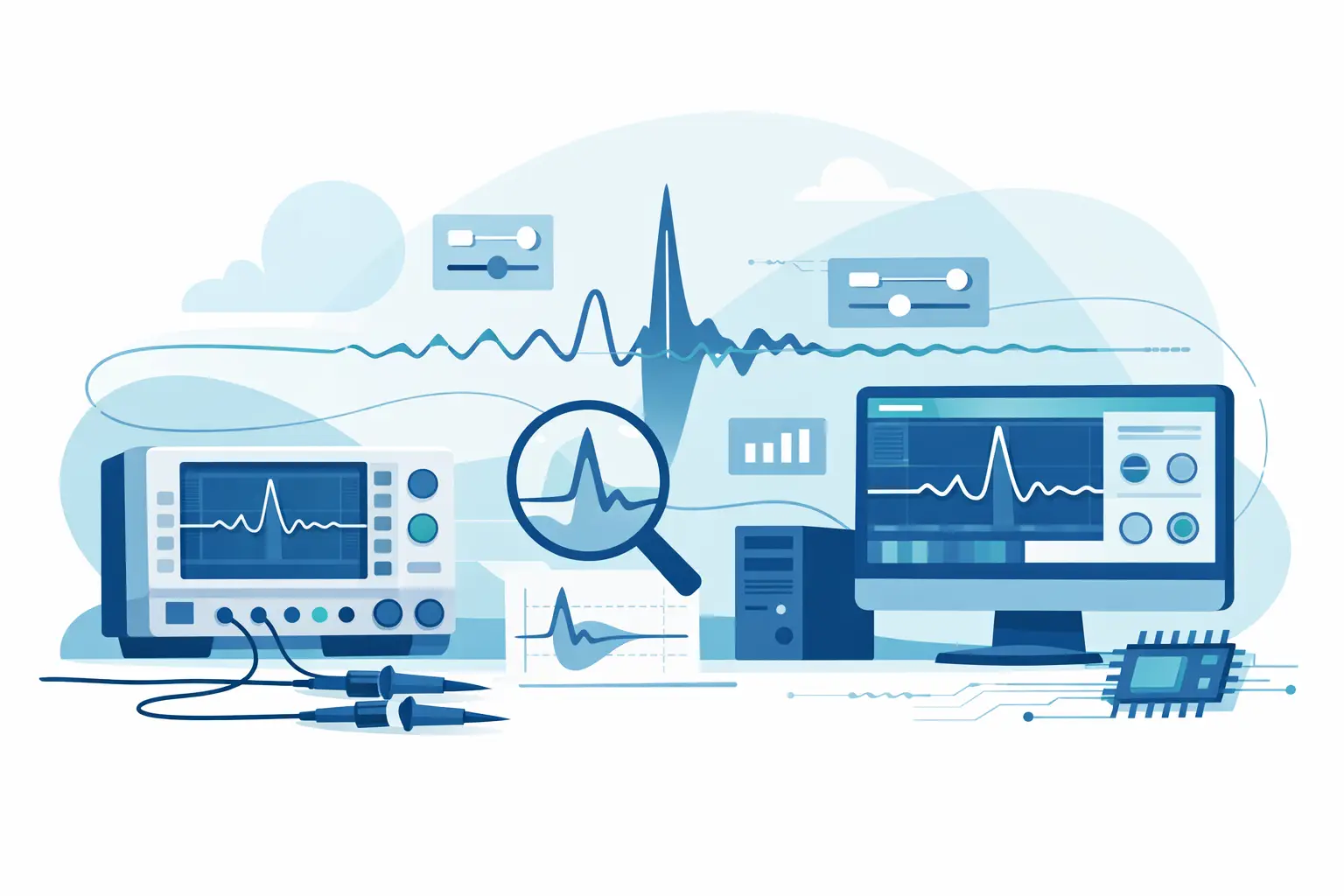
The difference matters because the acquisition requirements are not uniform. A slow thermal trend may only require modest sampling and long-duration recording. A switching transient, radar pulse, vibration signature, or intermittent fault can demand substantially higher bandwidth, pretrigger capture, and deterministic triggering. Overspecifying every channel increases cost, storage requirements, and review time. Underspecifying the critical channel can leave a test team without the evidence needed to explain a failure.
Signal Fidelity Comes Before Storage Capacity
Large storage capacity is useful only when the recorder captures a valid representation of the signal. The first engineering question is therefore not how long the system can record, but what frequency content, amplitude range, and event characteristics must be preserved.
Sample Rate, Bandwidth, and Resolution
The sample rate must support the highest frequency content of interest, with appropriate margin for the application and the anti-alias filtering strategy. Sampling at twice the frequency of interest satisfies the theoretical minimum for an ideal band-limited signal, but practical test systems often require higher rates to characterize waveform shape, transient timing, and harmonic content.
Analog bandwidth should be evaluated separately from sample rate. A high sample rate does not compensate for insufficient front-end bandwidth, poor filtering, or an unsuitable input configuration. Likewise, vertical resolution should be selected based on the smallest meaningful signal change after considering sensor range, gain, noise, and expected common-mode interference. A 16-bit digitizer does not automatically deliver 16 bits of useful information if the input range is poorly matched or the test environment is electrically noisy.
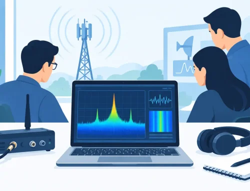
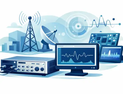
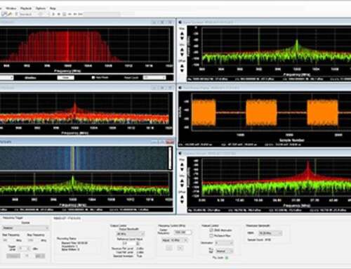
For high-speed electrical or RF/IF acquisition, engineers should examine effective number of bits, noise floor, spurious performance, input impedance, coupling options, and the stability of the sampling clock. These parameters influence whether weak signatures remain visible when stronger signals are present.
Triggering and Pretrigger Data
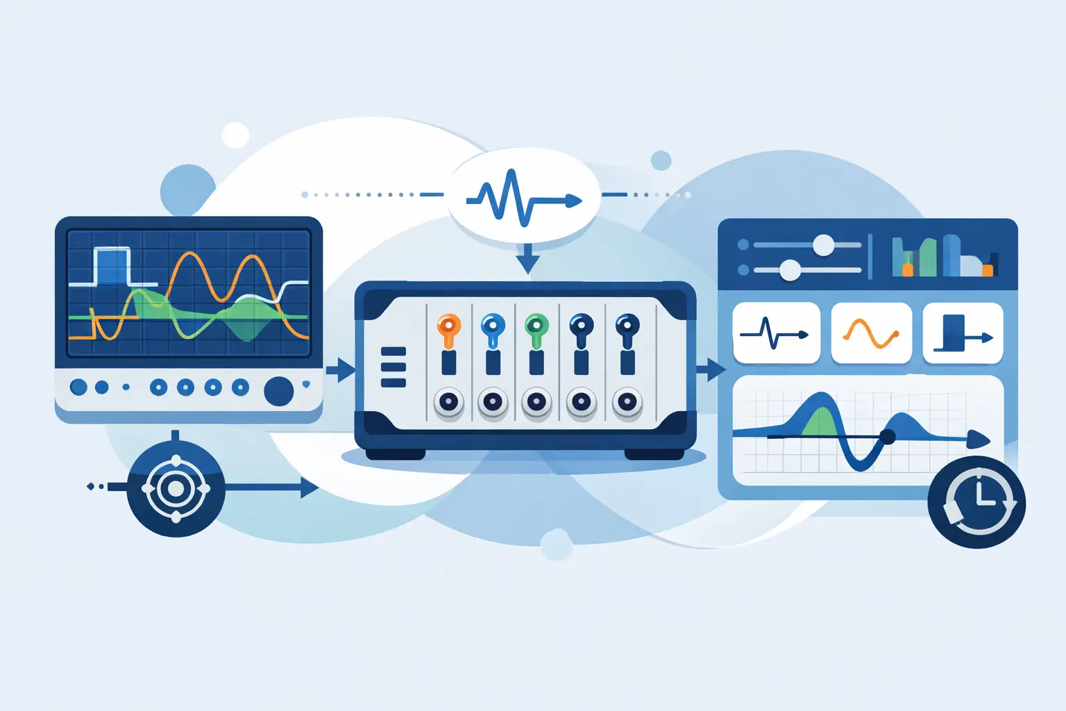
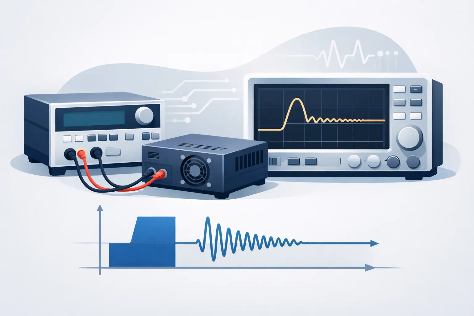
Many aerospace anomalies occur before the test team knows an event has happened. Triggering is therefore a central recorder capability, not a convenience feature. A usable system should support trigger conditions that match the test article: voltage thresholds, external discrete events, edge transitions, software commands, window conditions, or synchronized triggers from another instrument.
Pretrigger memory is equally significant. It captures the conditions leading up to the event, which may reveal a gradual drift, a preceding command, or a noise burst that initiated the failure. Posttrigger duration must then be long enough to characterize recovery, downstream effects, or a repeated sequence. The correct balance depends on event duration and the expected fault mechanism.
Time Alignment Is Part of Measurement Integrity
A waveform without reliable time context is difficult to correlate with telemetry, video, avionics buses, environmental chambers, or other test assets. Multi-channel systems need known channel-to-channel skew, stable clocks, and a documented method for synchronizing distributed instruments.
For a single chassis, simultaneous sampling may be necessary when phase relationships matter, such as three-phase power analysis, structural vibration, or actuator response. Multiplexed acquisition can be acceptable for slowly changing signals, but it can introduce time offsets that are unacceptable for transient or control-system analysis.
Across multiple recorders, teams may use a shared reference clock, GPS-derived timing, IRIG-B, or IEEE 1588 Precision Time Protocol, depending on the architecture and required uncertainty. The practical question is not which timing method is most familiar. It is whether the method provides sufficient accuracy, stability, and auditability for the engineering decision being made.
Timing should also be verified during setup. A synchronized status indicator is not the same as a measured time-alignment result. Where correlation is critical, inject a known event into relevant channels and confirm the recorded offset under actual system conditions.
Selecting Aerospace Data Recorders for the Test Environment
A recorder should be evaluated as a system component rather than as an isolated instrument. Electrical interfaces, physical installation, environmental exposure, data handling, and calibration requirements all affect whether it will support the program successfully.
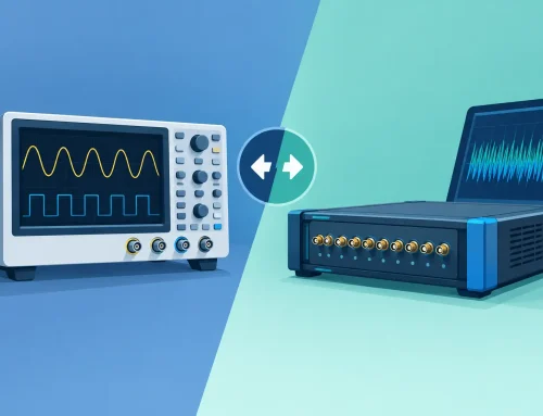
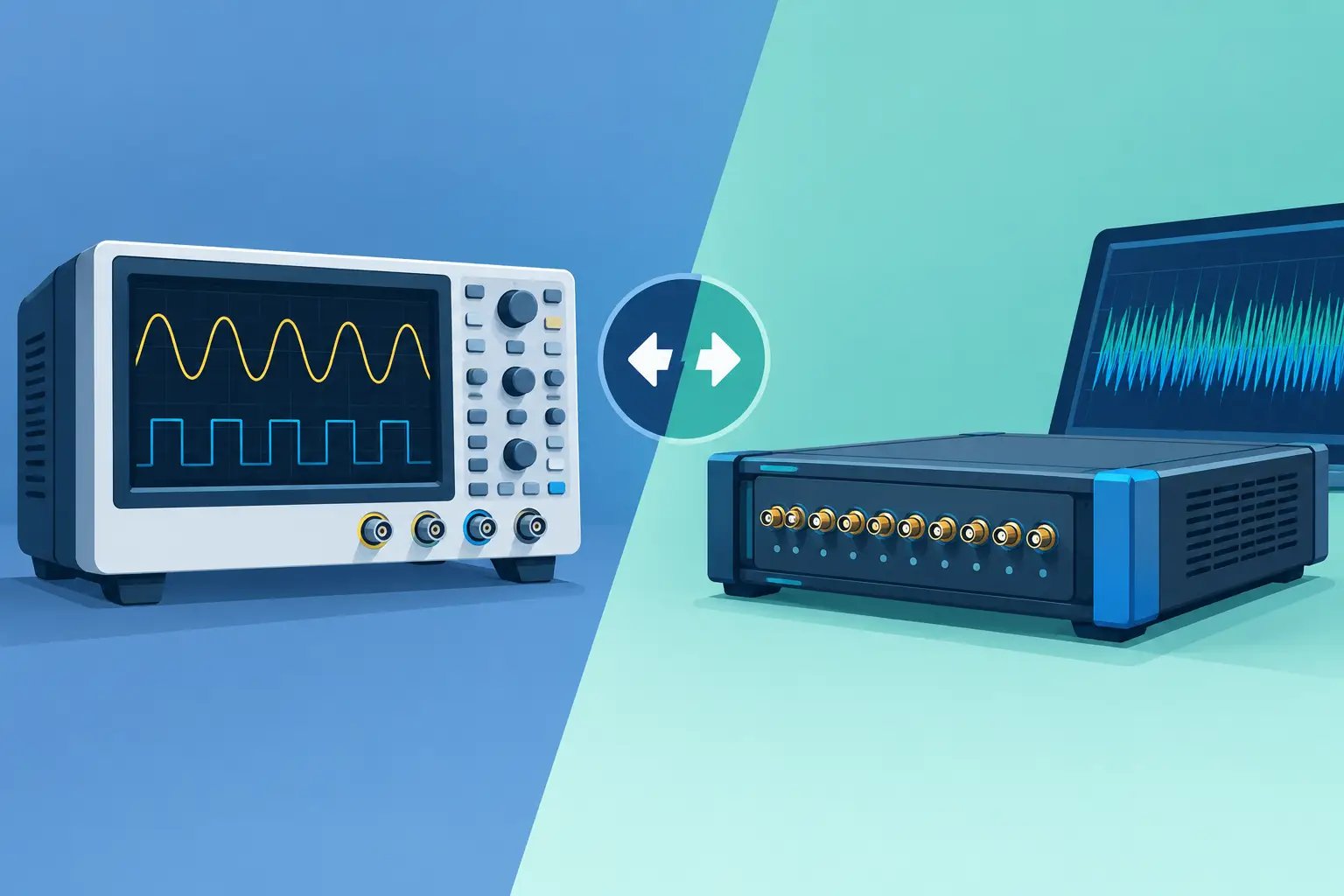
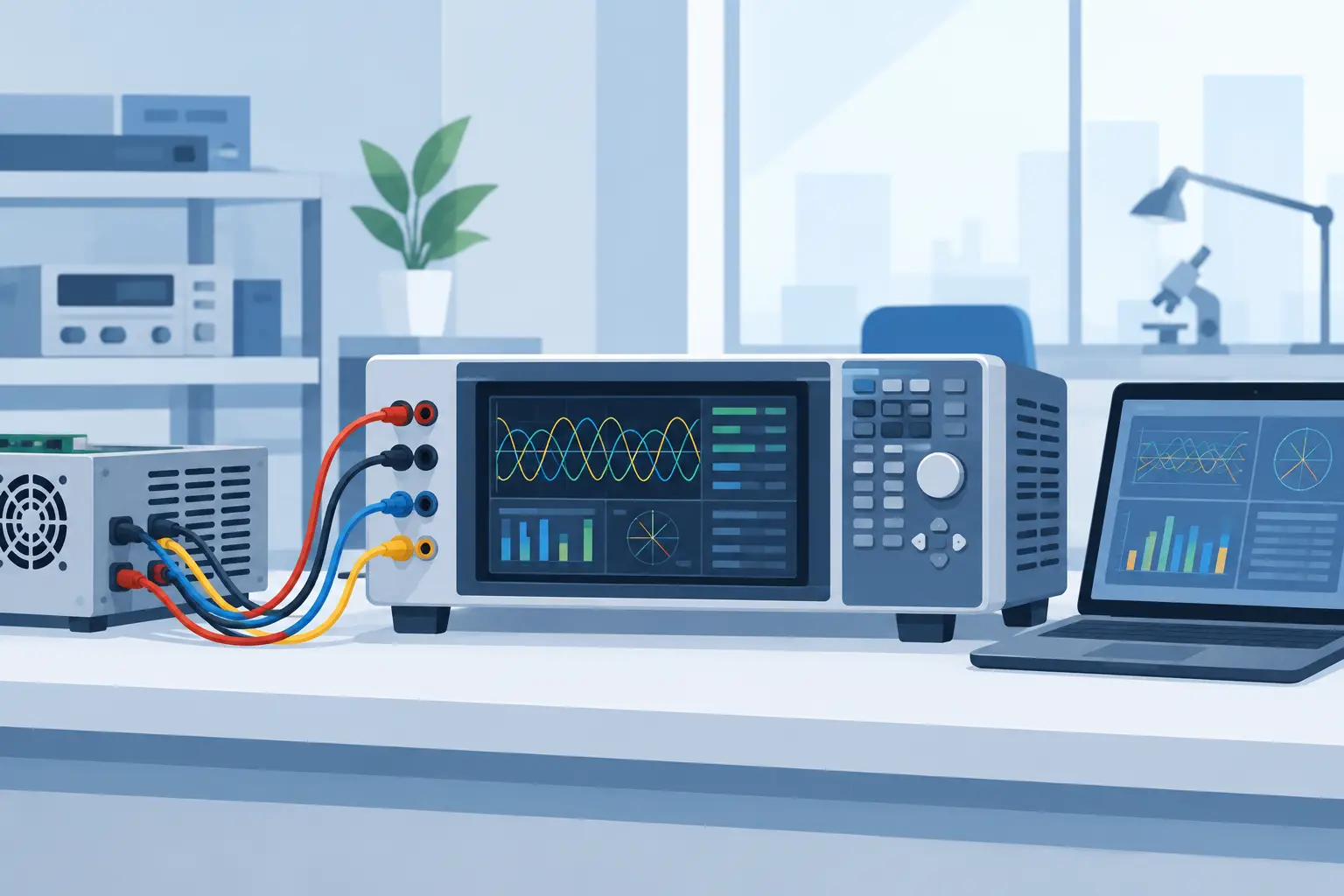
For laboratory and ground-test applications, a modular high-speed digitizer or RF/IF recording platform may provide the flexibility needed to scale channels, tailor memory depth, and integrate with automated test software. Systems such as those supported by the GaGe product family can be appropriate where high-speed waveform capture, configurable triggering, and software development support are central requirements.
For airborne or field deployment, the trade-offs change. Rugged packaging, connector retention, vibration tolerance, cooling approach, power conditioning, and storage reliability may take priority over bench convenience. If the recorder will be installed on an aircraft or subjected to military environments, the program should identify applicable environmental and design requirements early. Depending on the platform and procurement rules, this can include DO-160 environmental categories, MIL-STD-810 methods, electromagnetic compatibility requirements, or program-specific qualification plans.
Compliance language requires precision. A component used in a test rack does not necessarily need the same qualification evidence as hardware intended for permanent airborne installation. Conversely, labeling a system as rugged without reviewing the relevant environmental profile provides little value. Temperature range, altitude, vibration spectrum, shock level, humidity, conducted susceptibility, radiated emissions, and power interruption behavior should be evaluated against the actual mission or test environment.
Data Throughput and Retrieval Need an Engineering Plan
High-speed recording systems generate data volumes that can exceed assumptions made during test planning. A recorder may capture successfully while the downstream workflow fails: storage fills unexpectedly, transfer windows are too short, file formats become difficult to parse, or the analysis team cannot locate the relevant event among hours of data.
Estimate sustained data rate before procurement by accounting for channels, sampling rate, bit depth, metadata, and recording duration. Then evaluate memory depth, storage write speed, file segmentation, retention needs, and transfer interfaces. Triggered recording can reduce data volume dramatically when events are rare, while continuous recording may be essential for long-duration endurance or operational profiles. It depends on whether the failure is event-driven, cumulative, or only visible in its full temporal context.
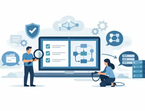
Data format and software access deserve equal attention. Engineering teams benefit from documented file structures, export options, application programming interfaces, and SDK support that allow data to move into established analysis environments. Proprietary software can be useful for acquisition control and rapid review, but the organization should retain a practical path to archive, retrieve, and independently analyze its measurements years later.
Calibration, Configuration Control, and Test Defensibility
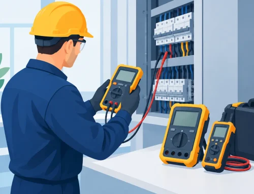
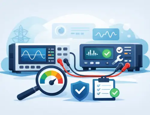
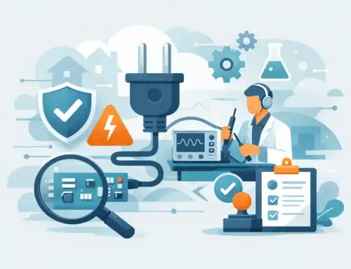
A recorder’s published specifications are meaningful only when its performance is maintained and its configuration is known. Calibration traceability, interval planning, verification procedures, and instrument health checks should be incorporated into the test process. For critical measurements, teams may also verify the complete chain from sensor through cable, conditioner, recorder input, and analysis scaling.
Configuration control is particularly important when multiple test articles, aircraft, or laboratories are involved. Record the installed hardware revision, firmware version, channel setup, input range, trigger logic, time source, calibration status, and sensor scaling with each acquisition. This information turns a waveform into usable engineering evidence rather than an isolated screen capture.
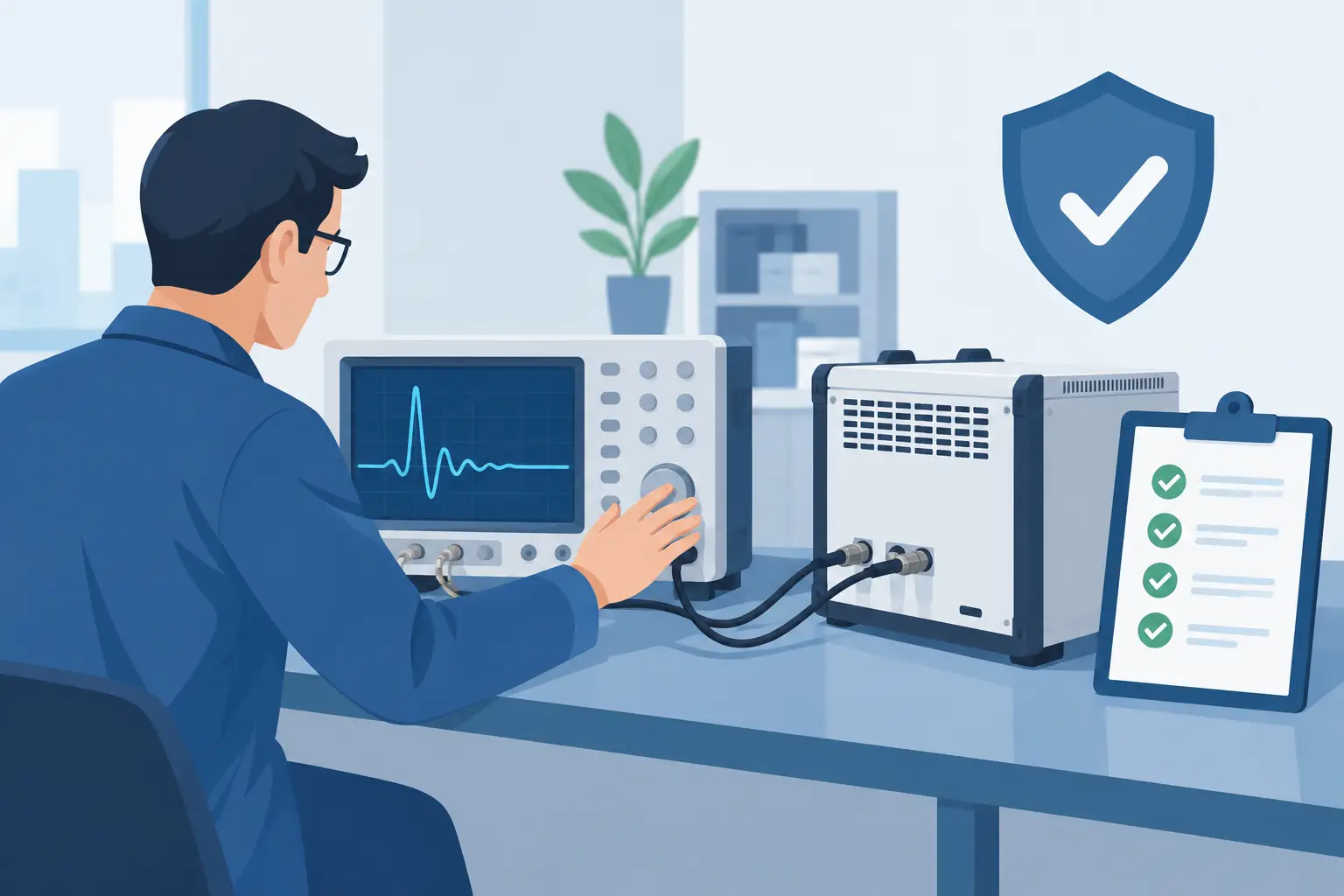
A short setup review before test can prevent expensive ambiguity later: confirm channel labeling, validate polarity, apply known input signals, test triggers, verify time alignment, and confirm that the planned record length includes pretrigger and posttrigger intervals. Those checks take less time than reconstructing an uncertain test after the hardware has been removed or the aircraft has returned to service.
The best recorder is the one whose limits are understood before the test begins. Match bandwidth, timing, environmental suitability, and data workflow to the failure modes you need to observe, then verify the complete measurement path under representative conditions. That discipline gives aerospace teams records they can trust when the test result matters most.