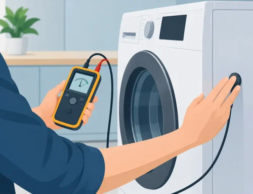
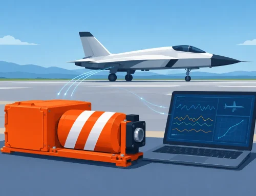
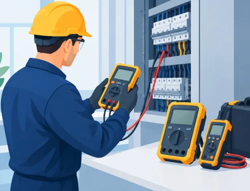
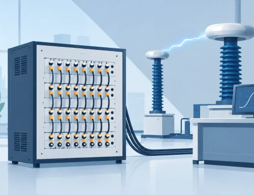
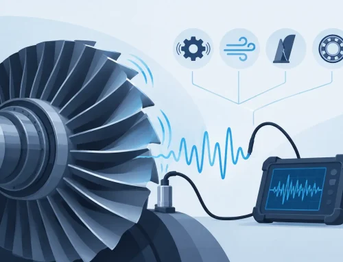
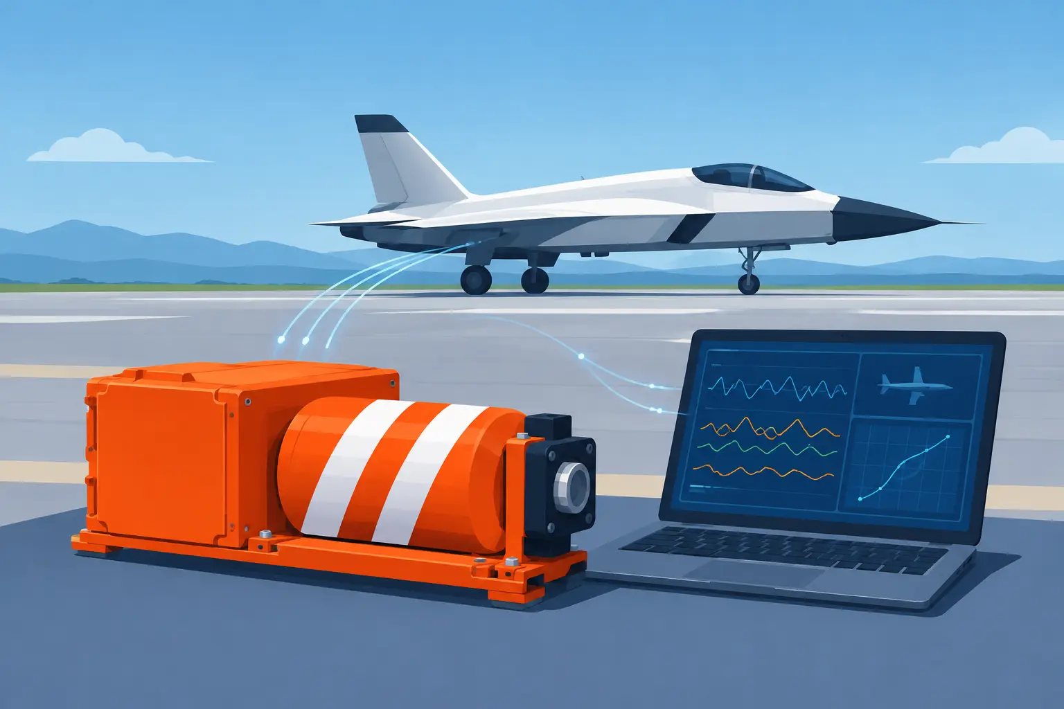
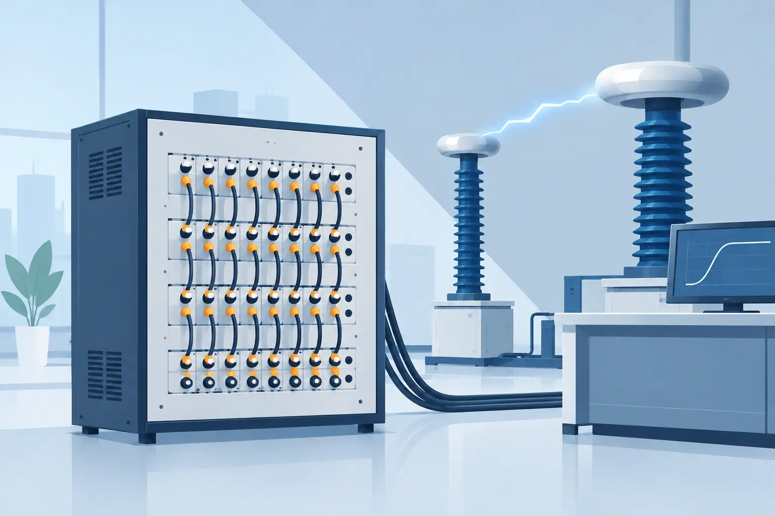
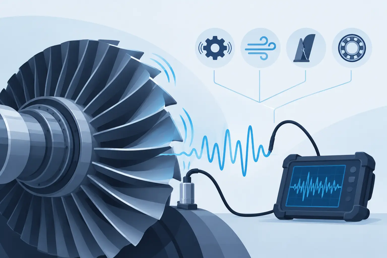
A transient appears once during a high-voltage switching test. A radar IF event must be recorded for later analysis. A multi-channel vibration test needs every sample aligned across a long acquisition window. In each case, the question of an oscilloscope versus high speed digitizer is not about which instrument is more capable in general. It is about whether the test requires immediate waveform visibility, sustained acquisition, deterministic integration, or data capture that can be analyzed long after the event has passed.
An oscilloscope and a high-speed digitizer can share fundamental building blocks: analog front ends, analog-to-digital converters, sample clocks, trigger circuits, and acquisition memory. Their practical roles, however, are different. Selecting the right platform affects test coverage, measurement confidence, automation effort, data-management requirements, and the ability to reproduce a result during engineering review or compliance investigation.
Oscilloscope Versus High Speed Digitizer: The Core Difference
An oscilloscope is primarily a self-contained measurement instrument. It combines acquisition hardware with an integrated display, front-panel controls, trigger setup, waveform processing, and measurement functions. An engineer can connect a probe, set vertical scale and time base, establish a trigger condition, and assess a signal within minutes. This direct interaction makes an oscilloscope highly effective for bench troubleshooting, circuit bring-up, design validation, and signal-integrity investigation.
A high-speed digitizer is designed first as a data-acquisition engine. It converts analog signals into digital samples and transfers or stores those samples for processing in a host computer or embedded test system. Rather than relying on a front panel and integrated display, digitizers use software, drivers, and software development kits to support custom workflows. Their value becomes especially clear when acquisition must be tightly synchronized, sustained over long records, automated across many test sequences, or incorporated into a rack-mounted system.
Neither approach is inherently superior. A scope reduces the time from signal connection to visual insight. A digitizer provides greater architectural control when waveform data is one component of a larger measurement system.
Start With the Measurement Objective
The instrument choice should follow the required measurement outcome, not simply sample-rate specifications. For a technician isolating ringing on a gate-drive signal or checking the rise time of a control pulse, an oscilloscope is usually the efficient choice. Its display, automated measurements, cursors, and triggering controls allow rapid iteration at the bench.
For an aerospace environmental test, a defense RF recording application, or a manufacturing diagnostic station, the requirement may be different. The team may need to acquire a defined record on several channels, associate it with serial numbers and operating conditions, store it automatically, and execute the same sequence hundreds of times. In that situation, a digitizer can be the more appropriate foundation because it is built to operate under software control within a repeatable system architecture.
The key question is simple: does the user need to observe a waveform now, or capture trustworthy data for processing, storage, correlation, and repeatable decisions? Many laboratories require both. The scope supports development and debug, while the digitizer supports deployed test and long-term data collection.
Compare the Specifications That Actually Matter
Sample rate and analog bandwidth are necessary starting points, but they do not resolve the decision on their own. A high sample rate cannot compensate for inadequate analog bandwidth, poor trigger behavior, insufficient memory depth, or an acquisition architecture that does not fit the test sequence.
Bandwidth, sample rate, and signal fidelity
Bandwidth defines the range of signal frequencies the analog input can pass within its specified response. It is central to preserving fast edges, RF content, and transient behavior. Sample rate determines the spacing of captured samples. For periodic signals, the Nyquist criterion establishes a theoretical lower boundary, but practical engineering work commonly requires oversampling to characterize waveform shape, timing, overshoot, and spectral content with confidence.
Both scopes and digitizers are available at high bandwidths and sample rates. The better choice depends on whether that performance must be accessed through an interactive instrument or integrated into a controlled acquisition platform. Engineers should also review effective number of bits, input noise, full-scale input ranges, impedance options, and the behavior of the front end under real signal conditions. A fast measurement that clips, adds excessive noise, or obscures small signal changes is not a useful measurement.
Memory depth and record duration
Record length is often the deciding factor. Acquisition time is determined by memory depth divided by sample rate. At high sample rates, a short memory fills quickly. This can be acceptable when inspecting a brief switching transition, but it can limit analysis when the event of interest is separated from its trigger by milliseconds, seconds, or longer.
High-speed digitizers are frequently selected for applications that require long, contiguous records or controlled multi-record acquisition. Examples include capturing startup behavior in power systems, recording IF signals, monitoring intermittent faults, and collecting vibration data through a complete test cycle. The required record should include pre-trigger context, the event itself, and sufficient post-trigger time to identify the system response.
Engineers should verify whether the published memory specification applies per channel, is shared between enabled channels, or changes with acquisition mode. They should also determine whether data can be streamed continuously at the needed rate and for the required duration. Sustained streaming is a system-level requirement involving the digitizer, interface, host computer, storage subsystem, and software architecture.
Triggering and event capture
A scope typically provides an accessible set of trigger modes for everyday debugging: edge, pulse width, runt, logic, serial pattern, and protocol-aware triggers in applicable models. This makes it exceptionally useful when an engineer is still learning what causes an intermittent event.
Digitizer triggering can be equally important, particularly when the acquisition must be initiated by an external system, synchronized with other instruments, or aligned with a physical test event. External triggers, clock references, pre-trigger capture, timestamping, and deterministic trigger latency may matter more than an extensive front-panel trigger menu. In automated systems, trigger reliability is part of measurement integrity. A missed event can invalidate an entire test run.
Channel count and synchronization
Multi-channel work deserves careful review. Comparing channel count alone is not enough. The relevant questions are whether channels sample simultaneously, share a coherent clock, maintain phase alignment, and can be synchronized with additional instruments.
A multi-channel oscilloscope can be very effective for observing related signals during development. A digitizer architecture may be preferred when a test system requires synchronized modules, external clock distribution, or coherent capture across a larger channel count. These requirements are common in phased measurement, vibration and modal analysis, power-conversion diagnostics, RF/IF recording, and hardware-in-the-loop test environments.
Integration Changes the Economics
The purchase price of an instrument is only one component of the cost of measurement. For a one-time investigation or a lab bench shared by many engineers, the integrated interface of an oscilloscope can save meaningful time. The user can obtain results without writing acquisition code, creating a data schema, or designing a custom display.
For repetitive production, qualification, or research acquisition, manual interaction can become the expensive path. A digitizer supports automated configuration, programmed triggering, pass/fail analysis, metadata capture, and file handling. It can also operate as part of a test executive that coordinates power sources, electronic loads, safety testers, environmental chambers, motion systems, and other instruments.
This advantage comes with responsibility. A digitizer-based system requires engineering effort for software validation, driver management, error handling, data storage, calibration planning, and cybersecurity controls where applicable. The most effective deployments define these requirements early rather than treating the digitizer as a plug-in replacement for a scope.
A Practical Selection Framework
Choose an oscilloscope when the primary need is interactive visibility and rapid troubleshooting. It is especially well suited to circuit debug, prototype evaluation, timing verification, and applications where engineers benefit from changing settings while watching the waveform response.
Choose a high-speed digitizer when acquisition must be automated, synchronized, sustained, or deeply integrated with a host application. It is often the right choice for long-record transients, multi-channel recording, custom analysis, remote operation, and test systems that must execute the same procedure with traceable consistency.
Before specifying either instrument, document the highest frequency of interest, minimum feature rise time, required sample rate, voltage range, input coupling, resolution, channel count, trigger source, pre- and post-trigger time, record length, repetition rate, and data-retention requirements. Add the environmental and operational constraints: rack space, calibration interval, support for required standards, software environment, and expected service life. These details identify limitations that a headline specification can hide.
Measurement Confidence Depends on the Complete Chain
The acquisition instrument is only one part of the measurement chain. Probes, cables, attenuators, current sensors, isolation methods, grounding practices, clock sources, and calibration status can influence results as much as the converter itself. This is particularly true in high-voltage, high-energy, and fast-switching environments, where poor interconnection practices can introduce noise, ground loops, distorted edges, or unsafe test conditions.
For regulated and mission-critical programs, establish documented settings and verification procedures for the complete setup. Calibration traceability, repeatable connection methods, controlled software versions, and retained raw data all help turn a waveform into defensible engineering evidence. Suppliers such as Vitrek support this system-level view by combining specialized acquisition hardware with the application expertise needed for demanding test environments.
The best choice is the instrument that preserves the event you need, at the fidelity you can defend, within a workflow your team can repeat. When the requirement is clear, the oscilloscope and the high-speed digitizer stop competing for the same job and become complementary tools in a disciplined measurement strategy.