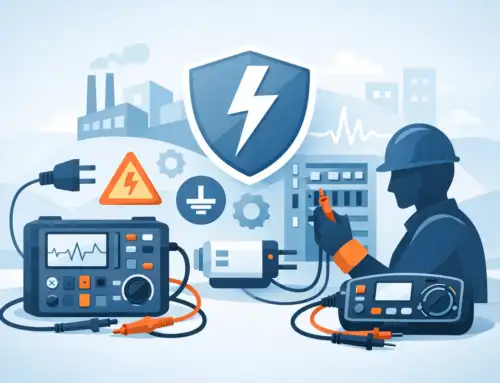
A product can pass dielectric withstand and insulation resistance testing yet still present an unacceptable accessible-current condition under normal operation or a single fault. To test appliance touch current correctly, engineers must measure current through a specified body-simulation network, at the required accessible locations, while the appliance operates in the conditions defined by the applicable standard. A meter connected directly between a conductive surface and ground does not provide an equivalent result.
Touch-current testing is therefore a measurement discipline as much as a safety test. The test method, measuring device, supply configuration, polarity, switching sequence, and documented test state all affect the result. For appliance manufacturers, test labs, and quality teams, controlling those variables is necessary to make defensible compliance decisions and to identify real design issues before production release.
What appliance touch current measures
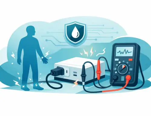
Touch current is the current that could flow through a person contacting an accessible conductive part of equipment. It may arise from intentional capacitive coupling in EMI filters, parasitic capacitance between energized circuits and accessible metal, insulation leakage, wiring errors, moisture contamination, or a component fault.
The term is often used broadly, but the governing safety standard matters. Depending on the product category and intended use, the applicable requirements may distinguish among touch current, leakage current, protective conductor current, patient leakage current, or other related measurements. Household and similar appliances are commonly evaluated to IEC 60335-1 and related product-particular standards, while information technology, laboratory, medical, and industrial equipment may follow different requirements and use different measurement networks or limits.
That distinction cannot be treated as a documentation detail. A result is meaningful only when it is measured with the network, frequency response, operating mode, and limit specified by the standard governing the product.
Why the measurement network matters
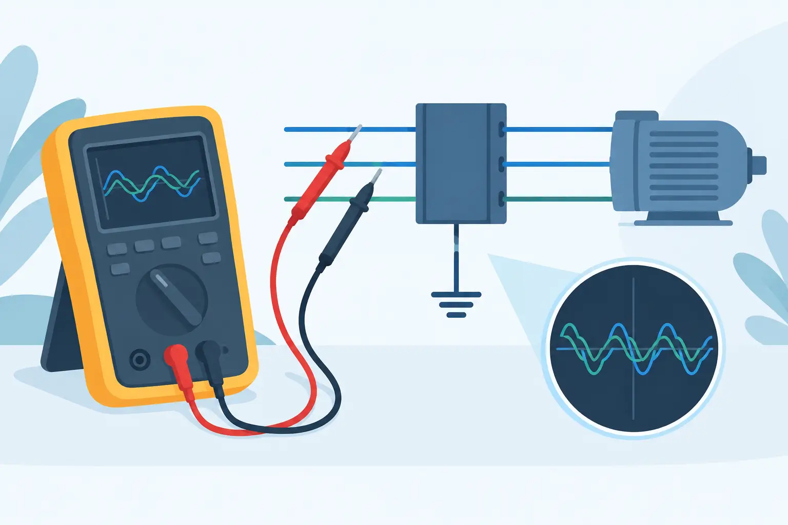
The human body is not a fixed resistor. Its impedance changes with frequency, contact conditions, and the current path through the body. Safety standards account for this behavior through a defined measuring device, often called a measuring network or body network. The network weights the current in a way that better represents physiological relevance than a direct current measurement alone.
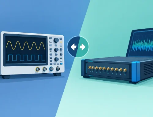
A conventional ammeter may show a different value because it has a different input impedance and frequency response. This is particularly significant in appliances containing switching power supplies, variable-speed drives, induction heating circuits, or EMI suppression capacitors. Those designs can generate non-sinusoidal or high-frequency components that a general-purpose meter may not capture or interpret correctly.
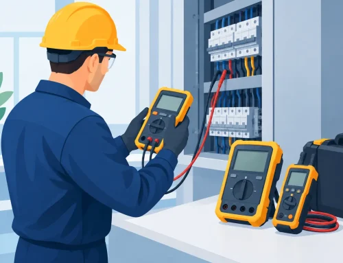
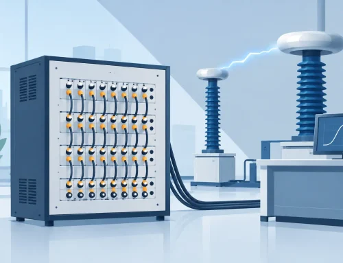
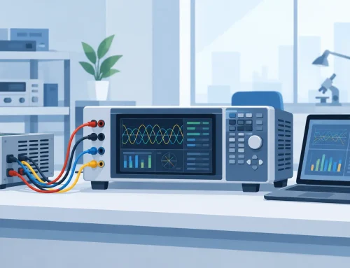
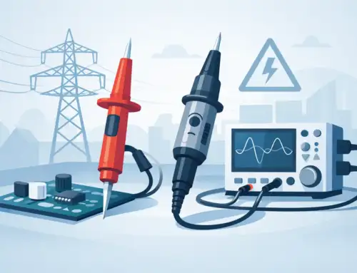
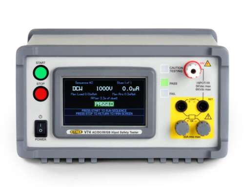
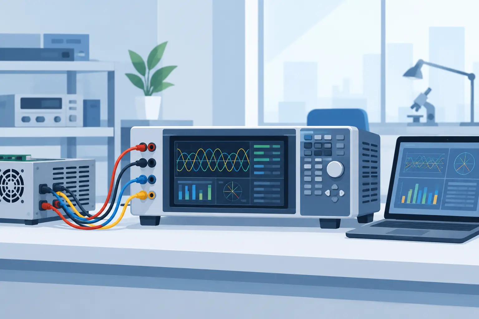
A purpose-built electrical safety tester with the appropriate measurement function improves repeatability by integrating the required network, controlled switching, programmable dwell times, and data capture. The objective is not merely to obtain a low reading. It is to obtain a reading that is traceable to the defined test method.
Touch current is not the same as protective conductor current
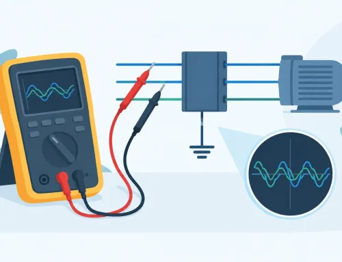
A Class I appliance uses a protective earth conductor as part of its shock-protection strategy. Protective conductor current measures current flowing in that conductor. Touch current evaluates the potential current through an accessible part and a person-simulating network.
The values may be related, especially where EMI capacitors are connected from line conductors to earth, but they are not interchangeable tests. A grounded enclosure may show acceptable touch current in one configuration while protective conductor current still requires evaluation against its own limit. Conversely, a fault or interrupted ground condition can change the touch-current exposure at accessible conductive parts.
Establish the applicable standard before setting the test
The most common source of poor touch-current data is not instrument accuracy. It is an incomplete test specification. Before configuring the tester, identify the product standard, edition, national deviations, product classification, rated supply range, accessible parts, and required normal and fault conditions.
The test plan should define whether the appliance is tested at rated voltage, the upper end of its voltage range, or another specified value. It should also define the power-switch position, functional modes, removable accessories, external connections, and any required reversal of supply polarity. A heating appliance, for example, may need evaluation during active heating, while a motor-driven appliance may need testing at startup, at steady state, and in each speed or control mode specified by the test plan.
For line-powered products, an isolation transformer or suitably controlled source may be necessary for a safe, valid laboratory configuration. However, the source arrangement must not defeat the reference conditions required by the standard. The test system should be designed and reviewed by qualified personnel who understand both the product standard and the facility’s electrical safety procedures.
A controlled method to test appliance touch current
The test begins with a defined unit condition. Confirm the appliance configuration, installation state, environmental conditioning if applicable, and connection of all required accessories. Inspect the unit for damage that could create an atypical exposure or invalidate the test.
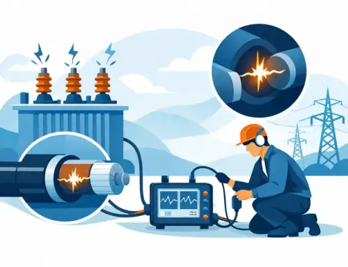
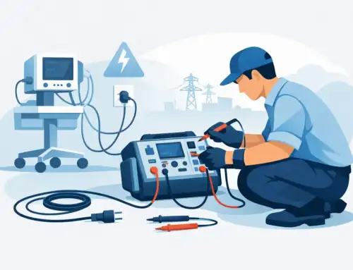
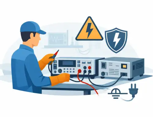
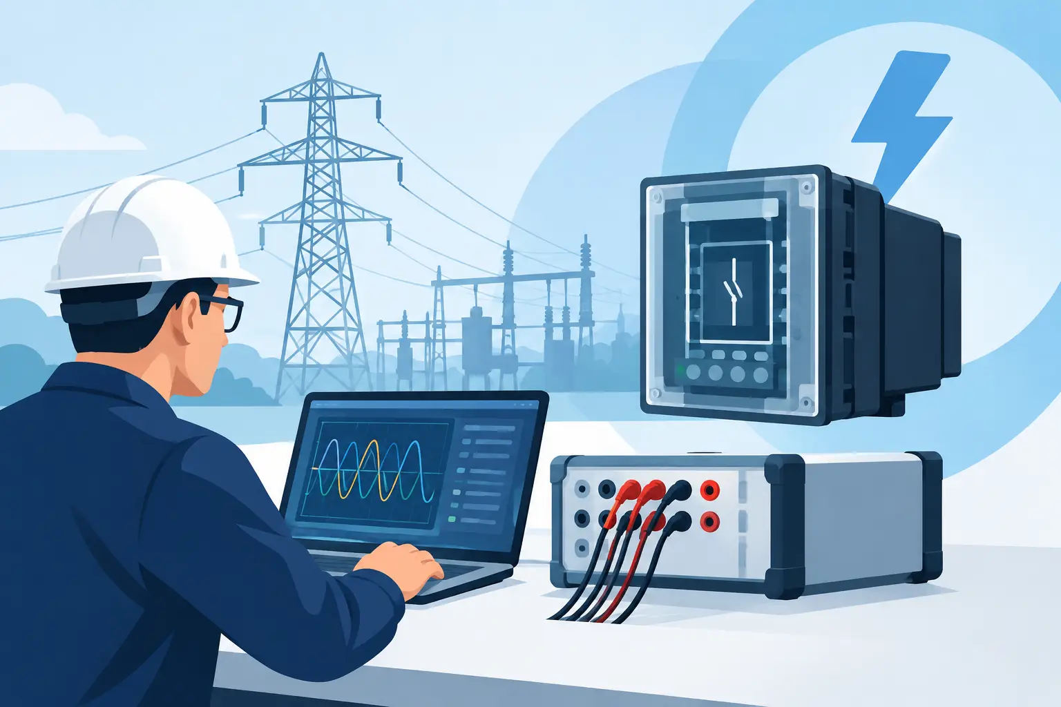
Next, connect the appliance to the required supply arrangement and connect the safety tester’s measurement lead to the accessible conductive part under evaluation. Depending on the appliance design, this may include an enclosure, control shaft, metal trim, fasteners, connector shells, handles, or parts made accessible after opening a user-serviceable cover. Insulating surfaces generally are not evaluated as conductive touch points, but contamination, coatings, and assembly details can affect accessibility judgments.
Apply the required operating condition and allow the product to reach the state specified by the standard or test plan. Measure through the designated network for the required dwell time. Repeat the measurement for required supply-polarity positions, switch states, operating modes, and fault conditions. Automated test sequences are valuable here because they reduce the risk that an operator omits a polarity reversal or records results from the wrong product mode.
The final step is review, not just pass/fail disposition. Compare the measured value with the applicable limit, but also assess the result against the product’s prior data. A unit that passes with a sudden increase from its normal baseline may indicate variation in an EMI filter, wiring routing, insulation system, moisture condition, or assembly process. Trend data often reveals a developing manufacturing issue sooner than a limit failure does.
Conditions that commonly change results
Touch-current readings can vary for legitimate reasons, but unexplained variation should never be normalized. Supply voltage is one factor. Capacitive current generally rises with voltage and frequency, so testing only at a nominal low-line condition may fail to characterize the highest expected result.
Product state is another. Heater cycling, motor speed control, compressor startup, relays, and switched-mode power conversion can each change the leakage path and waveform. For appliances with multiple modes, selecting one convenient steady-state condition may produce data that is repeatable but incomplete.
Fixture design also matters. Test leads should be short, secure, and routed consistently. Poor connections can introduce noise or intermittent readings, especially when evaluating low current levels. For high-volume production, a dedicated fixture with clearly identified probe points, guarded access, and interlocked test initiation supports both operator safety and measurement consistency.
Environmental conditions deserve attention when the product or standard calls for them. Humidity, contamination, condensation, and thermal stress can alter insulation behavior. A touch-current result obtained on a dry, room-temperature sample may not represent the condition after an environmental sequence or extended operating cycle.
Selecting instrumentation for repeatable results
The appropriate test platform depends on product volume, test complexity, required standards, and the need for integration. A development laboratory may prioritize flexible programming, waveform visibility, and the ability to investigate transient behavior. A production line may prioritize cycle time, fixture interfaces, barcode tracking, access control, and automatic result storage.
In both cases, verify that the instrument supports the required measurement network and relevant standard methods. Review its voltage and current ranges, bandwidth, measurement uncertainty, switching capability, calibration interval, and data-export options. Calibration traceability alone does not guarantee a valid test, but it is foundational to confidence in reported values.
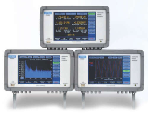
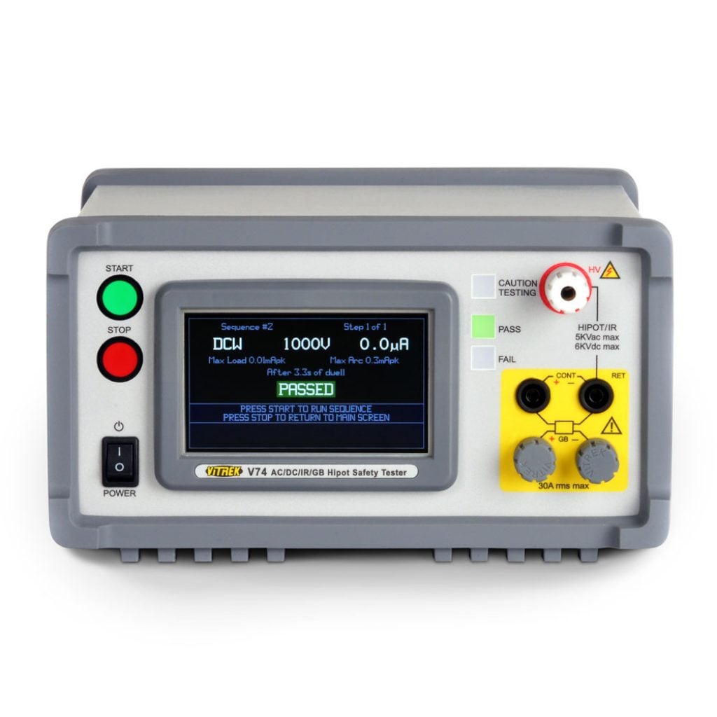
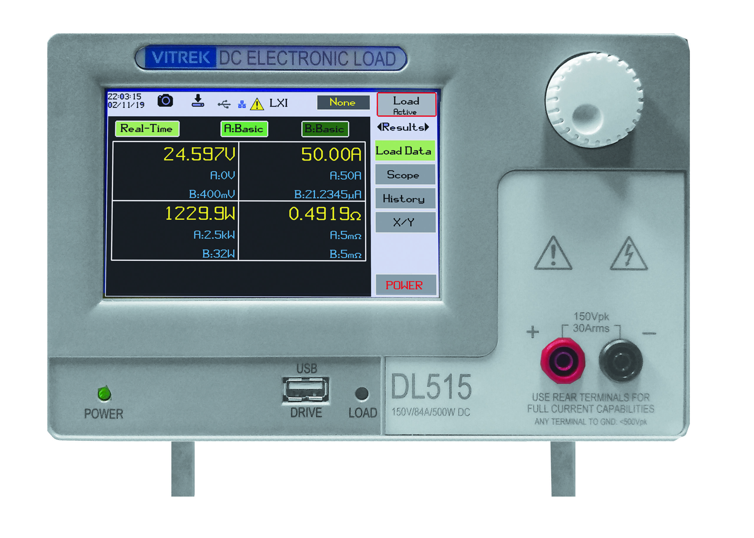
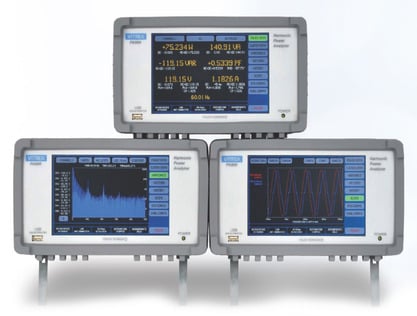
Vitrek electrical safety test systems are designed for controlled, repeatable hipot, insulation resistance, ground bond, and leakage-related safety testing in engineering and production environments. For complex appliance programs, the ability to combine programmed sequences with documented results can reduce operator dependence and improve audit readiness.
Document the result so it can be defended
A useful test record identifies more than the measured current. It should capture the product identification, serial number or sample number, applicable standard and clause, instrument identification and calibration status, measurement network, supply voltage and frequency, polarity, operating mode, accessible point tested, dwell time, ambient conditions when relevant, result, limit, and operator or system record.
This level of documentation supports certification work, production investigations, corrective actions, and field-return analysis. It also allows engineering teams to compare results after component substitutions or design changes. If a safety-critical measurement cannot be reconstructed from the record, its long-term value is limited.
Touch-current compliance is not achieved by connecting a lead and reading a number. It is achieved by applying the correct standard method to the actual appliance condition, using instrumentation that preserves measurement integrity, and treating unexpected trends as engineering evidence before they become product risk.