A thickness reading can look stable while still being wrong. On a moving web, a hot sheet, a curved composite panel, or a polished semiconductor surface, errors from alignment, vibration, surface reflectivity, and changing standoff can exceed the tolerance that matters. Selecting the best noncontact thickness sensors therefore starts with the measurement geometry and uncertainty budget, not a resolution figure taken from a data sheet.
For industrial metrology, the right system must measure the relevant surfaces without damaging the part, maintain traceable performance over time, and deliver data quickly enough to support the process. The best technology depends on the material, surface condition, thickness range, line speed, required accuracy, and environmental constraints.
What the Best Noncontact Thickness Sensors Measure
Noncontact thickness measurement is usually derived in one of two ways. The first method measures the distance to both sides of a part and subtracts the two gaps from a calibrated mechanical separation. The second measures through or across a material using a technology whose response is related to thickness.
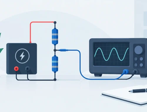
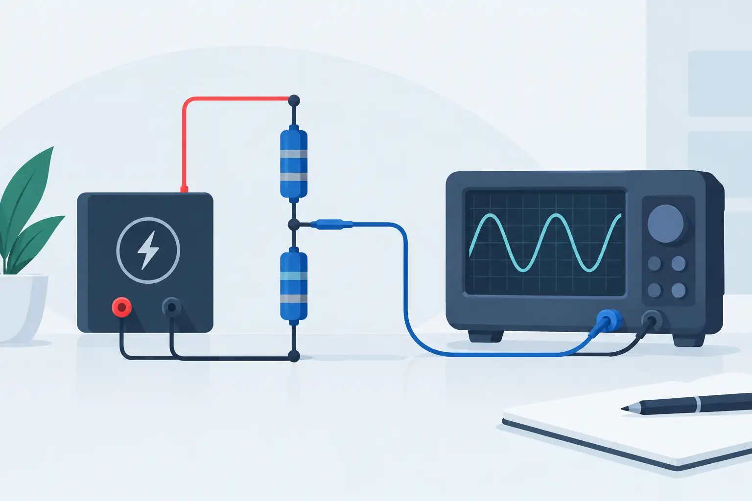
The first approach is common when both surfaces are accessible. Two opposed displacement sensors are mounted on a rigid frame, one above and one below the target. If the frame opening is known and both gap measurements are synchronized, thickness is calculated as:
`Thickness = calibrated frame separation – upper gap – lower gap`
That simple equation is only as reliable as the frame stability, sensor calibration, target alignment, and timing. A system with excellent single-sensor resolution may still produce poor thickness results if the measurement frame moves, the web flutters, or the two sensors sample at different moments.
The second approach is often used for continuous materials, multilayer products, or applications where only one side is accessible. Radiometric gauges, optical systems for transparent materials, and other application-specific methods can provide valuable process feedback. They also introduce their own material-dependent calibration requirements.
Sensor Technologies and Their Trade-Offs
Laser Triangulation Systems
Laser triangulation is a practical choice for many industrial thickness stations. With opposed sensors, it can measure sheet metal, rubber, composites, machined components, battery materials, and other opaque targets at useful working distances. These systems can support high sample rates and scanning arrangements for profiles across a web or panel.
Its limitations are strongly tied to the target surface. Specular metal, dark materials, translucent materials, sharp edges, and changing surface texture can affect optical return and measurement linearity. A target that changes angle as it moves through the station can also introduce error. Proper sensor selection, optical configuration, filtering, and fixture design are as important as nominal resolution.
Chromatic Confocal Sensors
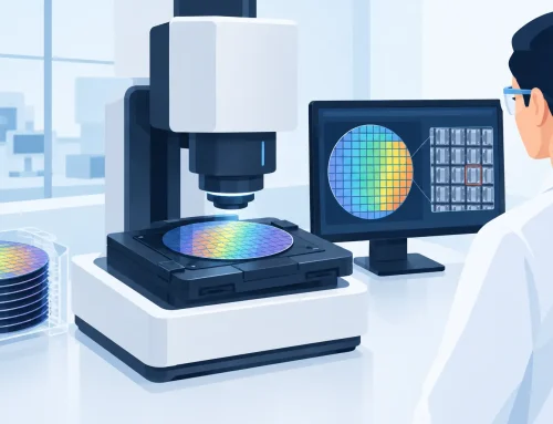
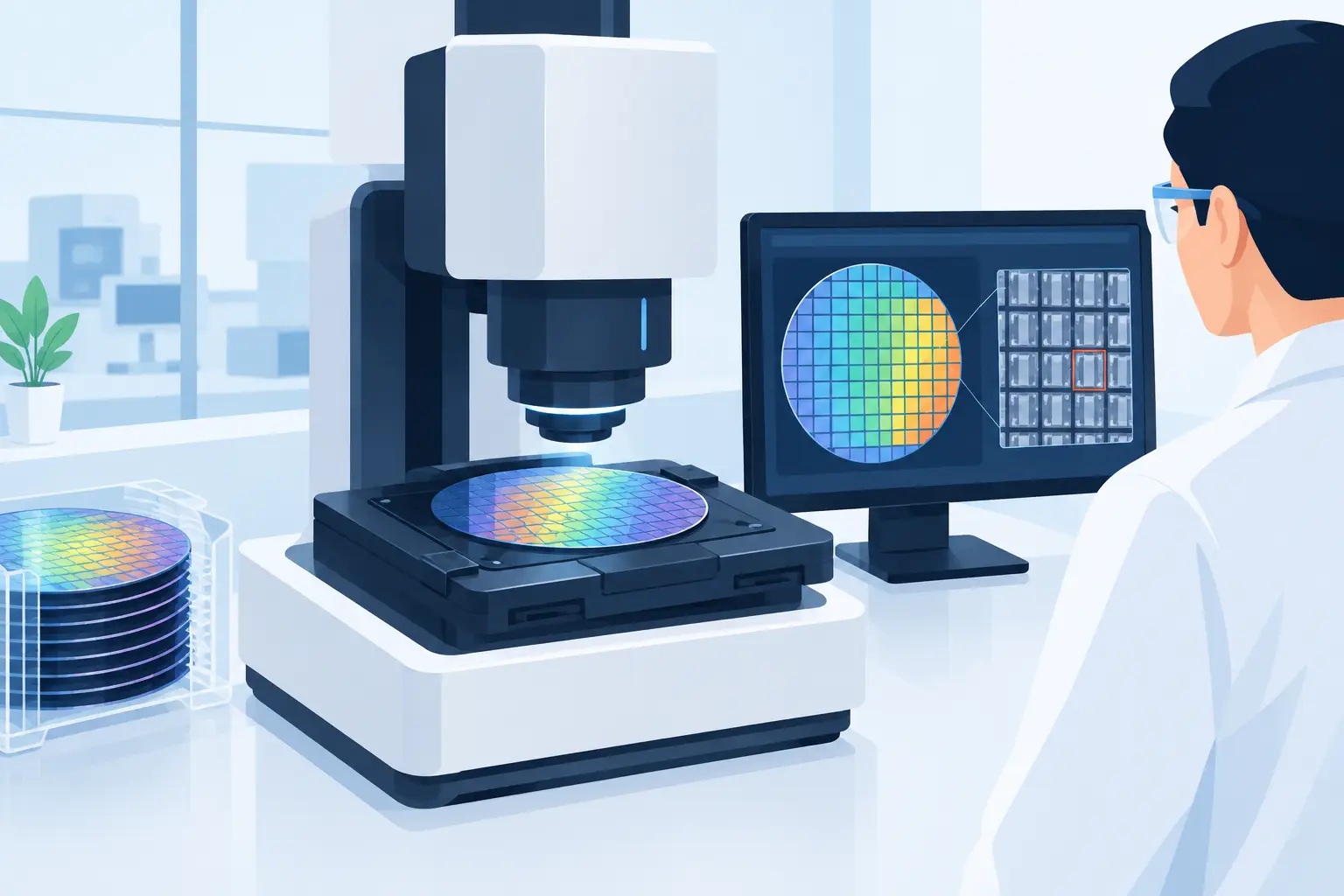
Chromatic confocal technology is well suited to applications requiring high axial resolution on smooth, reflective, transparent, or delicate surfaces. It is commonly considered for thin glass, films, coatings, semiconductor substrates, precision machined surfaces, and medical components.
Because the sensing principle uses wavelength focus rather than triangulation geometry, chromatic confocal sensors can perform well on challenging reflective surfaces and can measure certain transparent layers. The trade-off is typically a smaller measurement range, more demanding optical setup, and sensitivity to material optical properties in transparent applications. Engineers should confirm whether the required result is total part thickness, a particular layer thickness, or a distance to the first optical interface.
Capacitive Displacement Sensors
Capacitive sensors are highly effective for conductive targets when short standoff, exceptional repeatability, and very fine displacement resolution are required. In an opposed arrangement, they can provide precise thickness measurement of metal foils, conductive films, and other electrically conductive components.
Capacitive measurement requires disciplined mechanical and electrical design. The sensing area, target grounding, sensor-to-target alignment, nearby conductive structures, and target material all influence results. It is not a universal replacement for optical sensing, but it can be the preferred option when an optical surface is unreliable and the measurement conditions suit the technology.
Radiometric Thickness Gauges
X-ray, beta, and related radiometric gauges are frequently used for continuous production processes involving sheet, film, paper, coatings, and metal strip. They can measure through the material without requiring access to two separate surfaces, making them useful where an opposed sensor frame is impractical.
These gauges are generally selected for process measurement rather than micron-level dimensional inspection of individual components. Their output depends on material composition and calibration, and they may require radiation safety programs, regulatory controls, shielding, and specialized operating procedures. Those requirements can be justified on high-volume lines, but they should be evaluated early in the project.
Match the Measurement Method to the Application
The most useful first question is not, “Which sensor is most accurate?” It is, “What uncertainty is acceptable at the actual measurement point?” A 25-micron tolerance on a moving coated web requires a different architecture than a submicron thickness study of a polished wafer.
For a moving web, determine whether the material remains flat and stable through the measurement gap. Tension variation, flutter, curl, vibration, and lateral movement can create apparent thickness changes. A rigid C-frame or O-frame, guided material path, synchronized acquisition, and appropriate signal processing can matter more than choosing between two similarly specified sensors.
For discrete parts, fixturing often determines success. A curved part may require multiple measurement locations and normal-to-surface sensor alignment. Soft materials may deform under contact gauges, which makes noncontact sensing especially valuable, but the part must still be supported without introducing strain or sag.
For transparent materials, define the interfaces that must be measured. A sensor may detect the top surface, bottom surface, internal layer boundaries, or reflections from more than one interface. The correct optical method depends on refractive index, surface finish, coating stack, and whether the material is stationary or moving.
Selection Criteria That Affect Real Measurement Performance
Resolution is not the same as accuracy, and neither number alone establishes thickness-system capability. Evaluate the full measurement chain, including the sensor, controller, mechanics, motion, data acquisition, calibration standard, and operator method.
A useful review should address at least these five engineering considerations:
- Measurement range and standoff: The sensor must accommodate expected part variation while maintaining adequate sensitivity at the required working distance.
- Surface response: Test representative samples covering color, texture, reflectivity, curvature, coatings, and expected process variation.
- Dynamic performance: Verify bandwidth, sample rate, synchronization, and filtering against line speed and the smallest defect or variation that must be detected.
- Mechanical stability: Quantify frame deflection, thermal expansion, vibration, and sensor mounting repeatability under production conditions.
- Calibration and traceability: Establish a documented procedure using suitable masters or standards, including verification intervals and acceptable error limits.
Environmental effects should receive equal attention. Heat from a process can change the frame separation. Coolant mist, dust, steam, and airborne fibers can contaminate optics. Ambient light, electromagnetic interference, and facility vibration may affect different sensor technologies in different ways. A controlled laboratory demonstration is useful, but it should not replace an application trial that reflects the actual production environment.
Build the System Around Measurement Integrity
A thickness sensor is rarely a stand-alone answer. The measurement station should include a stable structure, appropriate part guidance or fixturing, synchronized channels, toleranced mechanical references, and software that records both thickness and supporting diagnostic data. Logging signal strength, gap values, sensor status, temperature, and material position can help distinguish a true product change from a measurement-system problem.
For automated inspection, determine how the result will be used. Closed-loop control may require low latency and carefully bounded filtering. Quality records may require time stamps, part identification, alarm limits, audit-ready data retention, and integration with plant systems. R&D programs may prioritize flexible acquisition, detailed waveform or profile capture, and software access for custom analysis.
This is where an instrumentation supplier with displacement metrology, high-speed data acquisition, and application support can reduce integration risk. Vitrek and its MTI Instruments portfolio address noncontact measurement applications where sensor performance must be paired with dependable system-level data.
Verify Performance Before Release
Before committing a system to production, perform a measurement system analysis with representative parts and process conditions. Compare readings against traceable standards across the intended range. Repeat the test after sensor repositioning, at different temperatures, with normal process vibration, and across shifts when applicable.
Also separate repeatability from reproducibility. A fixed test setup may repeat extremely well, while different operators, fixtures, material lots, or setups create unacceptable variation. The system should be accepted against the uncertainty needed for the product decision, not simply against the sensor’s best-case specification.
The best noncontact thickness sensor is the one that produces a defensible thickness value at the required speed, on the real material, in the real environment. Start with the part and process physics, then validate the complete measurement station before the data becomes a production decision.