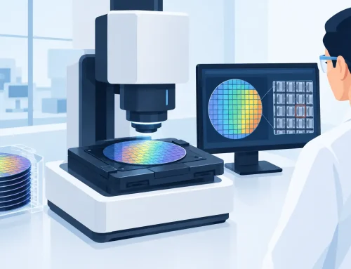
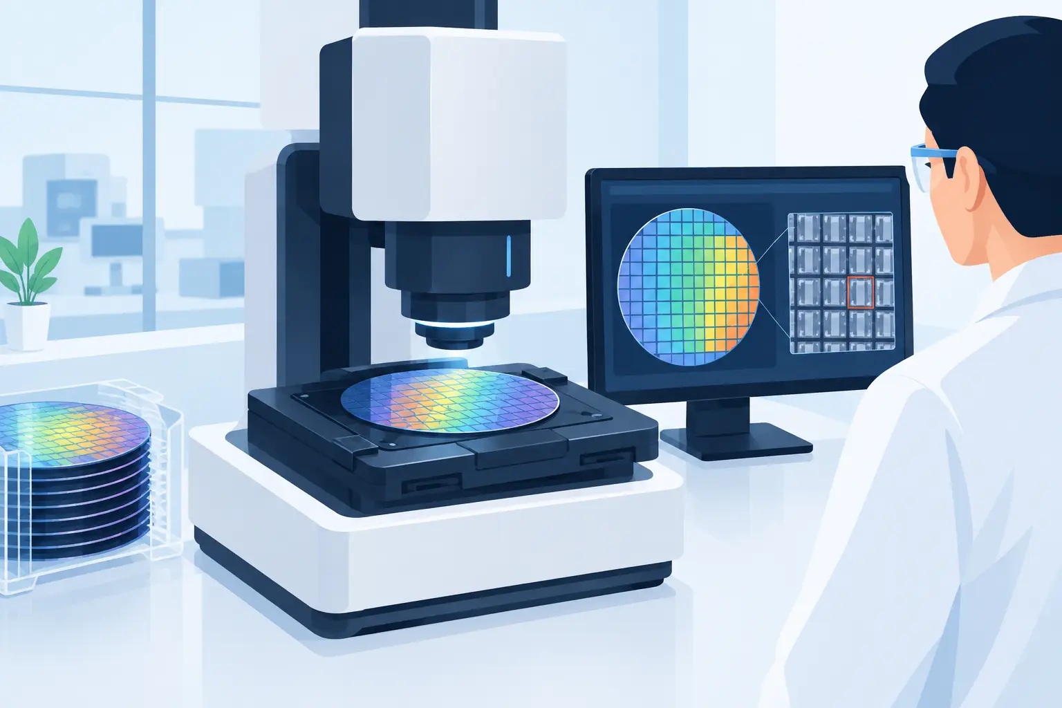
A power analyzer that agrees with a basic wattmeter at line frequency can still produce unusable results on a PWM inverter, high-crest-factor supply, or multi-phase motor drive. Selecting the best power analyzers for labs begins with the waveform, operating range, and uncertainty target of the device under test – not with a headline accuracy specification.
For engineering teams, power measurement is often a release criterion. It affects efficiency claims, thermal design decisions, energy-consumption certification, component sizing, and the defensibility of test records. The right instrument must therefore measure real operating conditions while preserving traceability and repeatability from one test station to the next.
Start With the Measurement Problem
A laboratory power analyzer measures voltage, current, power, energy, harmonics, phase, and related parameters. Its value lies in calculating these quantities accurately when voltage and current are not ideal sinusoids. This is a different task from viewing a waveform on an oscilloscope or obtaining a single power reading from a handheld meter.
Begin by defining the electrical environment. A power supply validation bench may need low-level standby-power measurement and high resolution at 50 Hz or 60 Hz. An EV inverter lab may need wide bandwidth, high-speed sampling, torque and speed integration, and synchronized measurements across DC bus and three-phase outputs. A renewable-energy or grid-interconnect application may prioritize harmonic content, transient capture, and compliance-oriented reporting.
The best instrument for one case may be unnecessarily complex or insufficiently capable for another. A highly accurate low-frequency analyzer can be a poor fit for switching-loss investigation if its bandwidth, synchronization, or current sensor arrangement does not support the application.
Accuracy Is an Uncertainty Budget, Not a Single Number
Published basic accuracy is necessary, but it is not enough for laboratory selection. Engineers should review the complete measurement uncertainty across the expected voltage, current, frequency, power factor, and temperature range.
At low power factor, small phase errors between voltage and current channels can create large errors in calculated watts. This is particularly relevant to inductive loads, transformers, motors, and power-factor-correction circuits. An analyzer specified for excellent accuracy at unity power factor may not deliver the required result at the phase angle present in the actual test.
Current range selection matters as much as channel accuracy. Using a 100 A range to measure milliamps of standby current sacrifices effective resolution. Conversely, operating close to the upper limit of a range can reduce measurement margin and overload tolerance. Labs that test products from sleep mode through full load benefit from analyzers with wide dynamic range, appropriate shunt options, and current inputs that retain performance across changing operating states.
Calibration traceability should also be evaluated before purchase. A calibration certificate alone does not establish suitability. Confirm the available calibration scope, interval, adjustment process, and documented uncertainty. For regulated programs and quality systems, those details determine whether a measurement remains defensible during audits and product qualification.
Bandwidth Must Match Switching Behavior
Modern power electronics have made bandwidth a primary selection factor. Wide-bandgap devices based on silicon carbide and gallium nitride can produce fast edges and switching frequencies that challenge instruments designed around conventional line-frequency measurements.
Bandwidth affects how faithfully an analyzer captures voltage and current content used in power calculations. Insufficient bandwidth can exclude relevant harmonic components, distort RMS and power results, or mask switching-related losses. Excess bandwidth, however, is not automatically better. A wider measurement band can admit more noise, and the correct configuration depends on the stated method, device physics, and frequency content that matters to the result.
This is why engineers should distinguish between fundamental-power measurements and switching-power measurements. For input-output efficiency tests, a defined bandwidth appropriate to the standard or application may be preferred. For inverter development, converter characterization, or loss analysis, a higher-bandwidth instrument and carefully specified sensors may be required.
The sensor path deserves the same scrutiny as the analyzer. A precision power analyzer connected to an unsuitable current transformer, clamp, shunt, or probe will not deliver precision results. Verify sensor bandwidth, phase shift, saturation behavior, conductor geometry, and calibration status as part of the total system.
Channel Count and Synchronization Define What You Can Prove
Laboratory test setups rarely remain simple. A single-phase supply may become a three-phase motor test. A DC source may need to be compared with three AC output phases. Mechanical output, environmental data, or control signals may need to share the same time base.
For multi-phase applications, simultaneous sampling and channel-to-channel synchronization are essential. Time skew between channels creates phase error, which directly affects power calculations. The requirement becomes more demanding when comparing input and output efficiency, evaluating regenerative operation, or correlating electrical performance with torque, speed, temperature, and controller commands.
Consider both the channel count required today and the architecture required over the life of the lab. A four- or six-channel configuration may cover a DC bus plus three-phase output, while more complex systems may require expansion, synchronized instruments, or integrated data acquisition. Buying only for the immediate test can force awkward workarounds when the program moves from component characterization to system-level validation.
Evaluate Data Handling as Carefully as Measurement Hardware
A power analyzer is part of a test system, not an isolated display. Test engineers need a practical route from measurement to analysis, report generation, and archived evidence.
Review communications interfaces, command sets, software drivers, data formats, and SDK availability. Automated test environments often rely on Python, C#, LabVIEW, MATLAB, or proprietary production-test frameworks. The instrument should support deterministic remote control, clear status reporting, reliable error handling, and data retrieval that preserves units, scaling, timestamps, and configuration metadata.
For R&D, trend displays and numerical readouts may be sufficient during early experimentation. For design verification or production engineering, the ability to save instrument settings with results is more valuable. Without configuration records, a result can be difficult to reproduce even when the raw power data appears complete.
Triggering and external synchronization can also be decisive. If a device cycles through startup, burst mode, protection events, or regenerative transitions, averaged readings can conceal the behavior that caused a failure. A system that coordinates power data with high-speed digitization or other acquisition channels provides a clearer diagnostic path.
Choose Features That Serve a Defined Application
A practical comparison of the best power analyzers for labs should include the functions that shorten a specific test workflow, rather than every available option. Harmonic analysis can support grid-quality and compliance work. Energy integration can support endurance and consumption testing. Motor-analysis functions can correlate electrical input with speed and torque. Efficiency calculations can reduce manual post-processing in converter and appliance testing.
These features still require engineering judgment. An automated efficiency calculation is only as valid as the wiring, range selection, sensor compensation, bandwidth configuration, and synchronization behind it. Teams should verify performance with known loads and documented setup procedures before using automated values as release data.
Safety is equally application-specific. Confirm the voltage category, insulation ratings, input limits, protective grounding requirements, connector design, and safe current-sensing approach. In high-energy battery, inverter, aerospace, and industrial systems, the test fixture and interconnect design may carry greater risk than the analyzer itself. The instrument must fit a controlled test method that protects personnel, equipment, and data integrity.
A Specification Process That Avoids Expensive Mismatches
Before requesting demonstrations or quotations, document the expected minimum and maximum voltage, current, frequency, power factor, crest factor, and switching frequency. Add the number of phases, required channels, expected sensor type, target uncertainty, and applicable standards. Include the software environment, automation needs, calibration expectations, and the data that must be retained for quality or certification purposes.
Then evaluate candidate instruments using representative devices under test, not only a resistive load. A representative demonstration should include the operating modes that create measurement risk: low standby power, distorted current, low power factor, high-current operation, switching transitions, or regenerative energy flow.
Vitrek power analyzers are designed for applications where precision electrical measurement, flexible system integration, and repeatable test data are central requirements. As with any laboratory platform, the appropriate configuration depends on the ranges, bandwidth, channel architecture, and automation objectives defined by the test plan.
The most productive purchase decision is one that treats the analyzer, sensors, fixture, automation software, and calibration program as a single measurement chain. Define that chain before the equipment arrives, and the resulting data will be far more useful when a design review, customer audit, or certification question demands an answer.