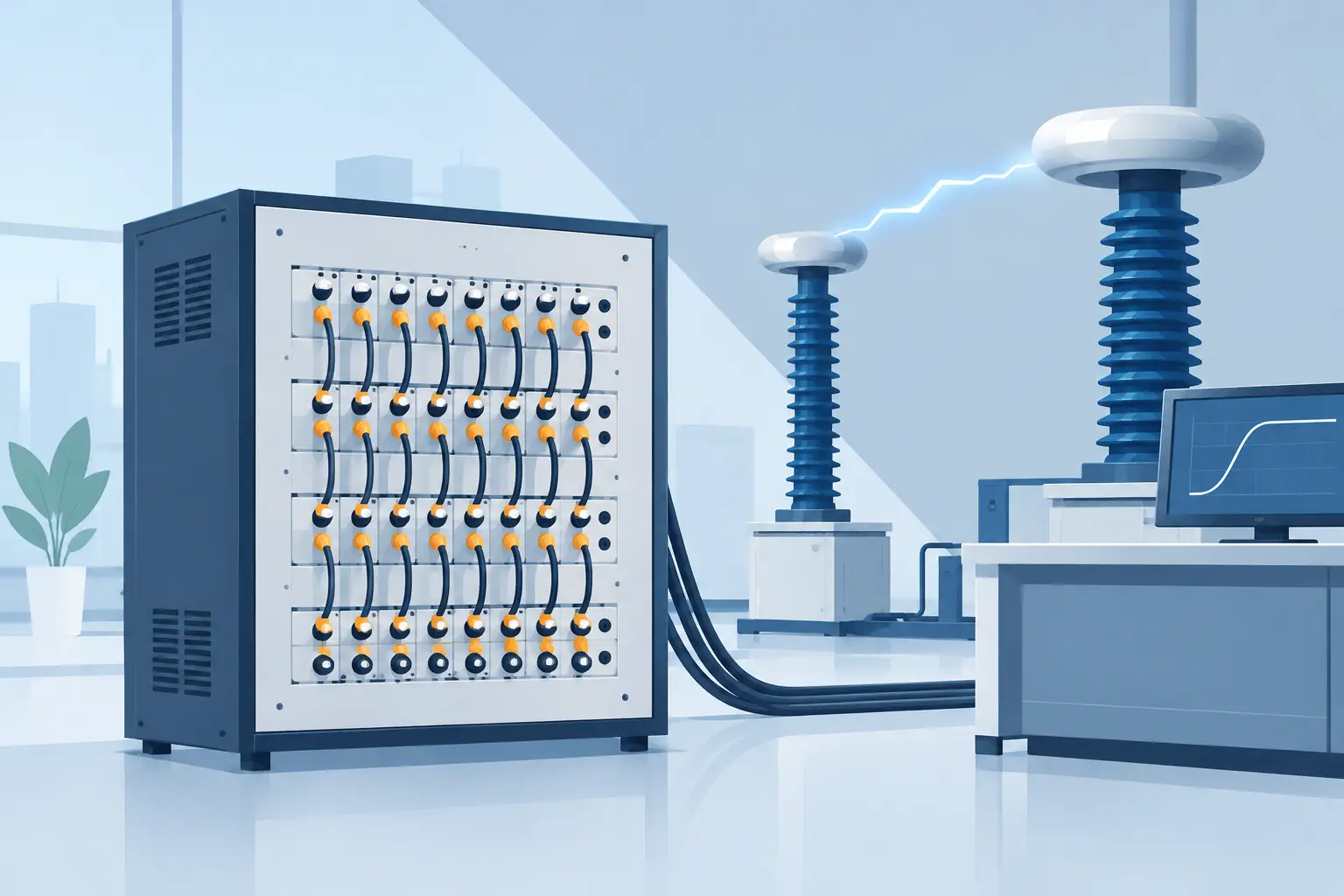
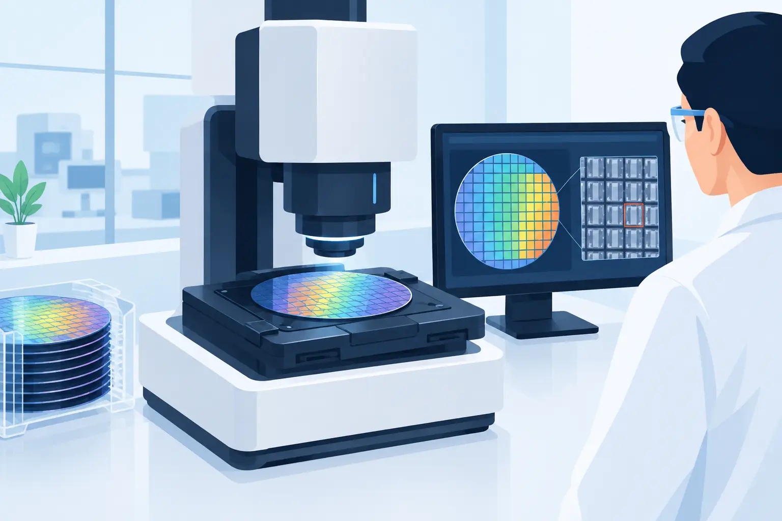
A noncontact displacement sensor can be specified correctly and still produce unreliable results if its controller is treated as an accessory. In precision measurement, noncontact sensor controllers establish the excitation, signal conditioning, digitization, filtering, scaling, and communications path that turns a changing gap into usable engineering data. Their performance directly affects whether a system can distinguish actual part movement from electrical noise, thermal drift, fixture instability, or process variation.
For engineers measuring runout, shaft position, wafer geometry, surface motion, or critical assembly gaps, controller selection should begin with the measurement objective rather than a channel-count requirement. The right controller is the one that preserves the needed measurement uncertainty under real operating conditions, including changes in temperature, target material, cable routing, machine vibration, and acquisition timing.
What Noncontact Sensor Controllers Do
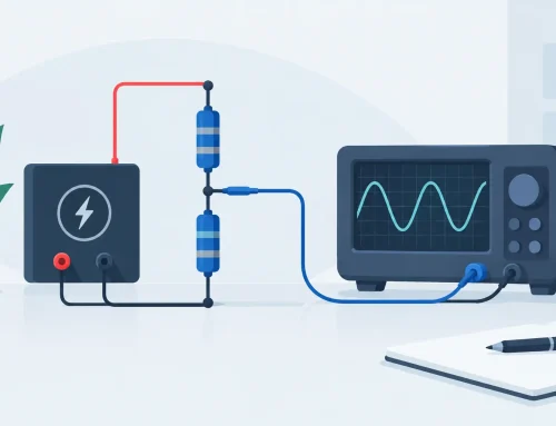
A controller supplies and interprets the operating signal for a noncontact probe. In capacitive measurement systems, for example, the controller drives the sensor and converts the resulting change in capacitance into a calibrated displacement output. The controller then provides that value through analog outputs, digital interfaces, or both.
That function sounds straightforward, but several performance characteristics are determined at the controller level. These include measurement range, bandwidth, output noise, linearity, sampling behavior, synchronization capability, and the available filtering options. A probe and controller should therefore be evaluated as a matched measurement system, not as independent components selected by lowest cost or nominal compatibility.
Controller choices also shape integration effort. A laboratory setup may only need a stable analog voltage output and a local display. An automated production cell may require synchronized multi-axis acquisition, deterministic data transfer, software control, alarm thresholds, and traceable storage of measurement records. These are materially different applications, even when both use the same sensor technology.
Start With the Measurement Requirement
The most productive specification process begins by defining what must be measured, where it occurs, and what decision will be made from the result. A controller intended to monitor bearing motion at high speed is not necessarily appropriate for submicron flatness characterization, where lower bandwidth but exceptional noise performance and long-term stability may matter more.
Establish the required measurement range first. The operating range must cover expected movement, alignment tolerance, and transient excursions without placing normal operation near the limits of the calibrated range. At the same time, excessive range can reduce sensitivity. If an application requires nanometer- or micrometer-scale discrimination, specifying more range than necessary may impose an avoidable resolution penalty.
Next, define the smallest meaningful change. This is not always the same as the controller’s published resolution. The relevant question is whether system noise, including the sensor, controller, cabling, target, fixture, and environment, remains low enough to reliably detect the change that matters. A specification measured under controlled laboratory conditions is useful, but it should be compared with expected field conditions.
Bandwidth requires similar discipline. Higher bandwidth allows the system to follow faster events, but it also admits more noise. A high-speed spindle, vibration test fixture, or transient mechanical process may need wide bandwidth and a sampling system capable of capturing it without aliasing. For a slowly changing dimensional measurement, limiting bandwidth can improve repeatability by reducing noise. The best setting depends on signal dynamics, not simply on the highest available performance number.
Match the Controller to the Sensor and Target
Sensor-controller compatibility extends beyond connector fit. The controller must support the probe’s operating principle, range, sensitivity, cable length, and calibration method. Substituting a cable or sensor without confirming the approved configuration can change sensitivity, increase noise, or invalidate calibration data.
Target characteristics also matter. Capacitive sensors are highly sensitive to the electrical properties and geometry of the target. Conductive target material, effective target area, curvature, surface condition, and grounding arrangement can all affect the measurement. A controller calibrated against a flat, grounded metallic target may require a different calibration approach when measuring a small curved component or an application-specific fixture.
For applications involving conductive and nonconductive materials, changing surfaces, or larger stand-off distances, a different sensing technology may be more suitable. The controller decision should follow the sensor technology decision, but the two should be made together. A technically capable controller cannot compensate for a sensing method that is poorly matched to the target.
Consider cabling and grounding early
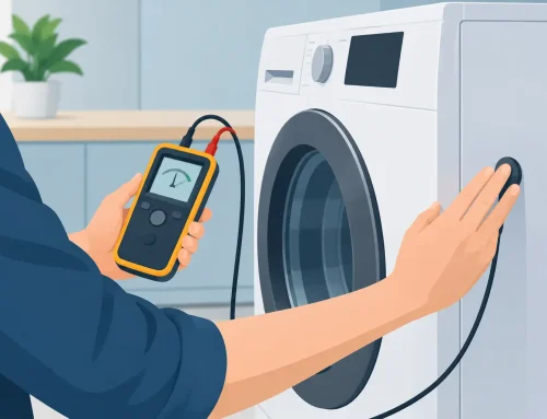
Many apparent controller problems originate in the installation. Sensor cables should be routed away from motor leads, switching power supplies, RF sources, and high-current conductors where practical. Cable length and type should remain within the system manufacturer’s approved limits. Ground loops, poor shielding termination, and an unstable target reference can introduce low-frequency drift or periodic interference that resembles actual displacement.
A pre-installation review should document sensor mounting, target grounding, cable routing, controller location, and the interface to the data acquisition or control system. This is particularly valuable in production environments, where a measurement system may be installed long after the original design team has moved on.
Evaluate Noise, Stability, and Repeatability Together
Resolution alone is not a complete indicator of measurement quality. A controller may display very fine digital increments while the actual signal fluctuates by several times that amount. Engineers should review RMS noise, peak-to-peak noise, linearity, thermal behavior, and repeatability over the relevant time period.
Short-term repeatability supports immediate process decisions. Long-term stability matters when measurements are compared across shifts, batches, maintenance intervals, or test locations. Temperature changes can affect electronics, cabling, fixtures, and the measured part itself. If the process involves a thermal chamber, a warm production line, or cycling equipment, characterize the entire setup over the expected temperature range.
Filtering can improve displayed stability, but it should not conceal meaningful motion. A low-pass filter may be appropriate for a static gap measurement, yet it can distort a rapid mechanical event or delay a control response. Document filter settings as part of the measurement method, especially where results support quality acceptance, compliance records, or product validation.
Plan the Data Interface Around the Test Workflow
The output format should serve the system that uses the data. Analog outputs remain effective for legacy data acquisition hardware, machine control, and simple monitoring. Their limitations include susceptibility to external noise, scaling errors, and the need to confirm input range and grounding compatibility at the receiving device.
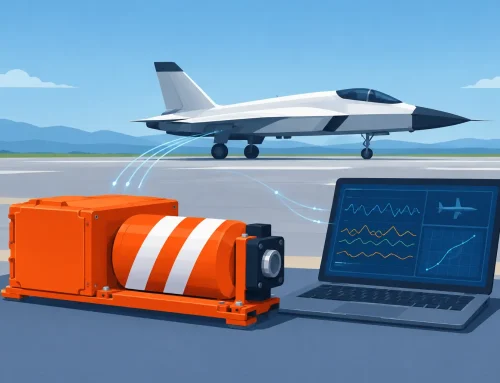
Digital interfaces can simplify configuration, provide higher-level status information, and support automated data collection. They are especially useful when a test sequence needs to record controller settings, sensor identification, alarms, and measurement values alongside other test data. Interface selection should account for update rate, latency, software support, protocol compatibility, and whether the host system must synchronize multiple channels.
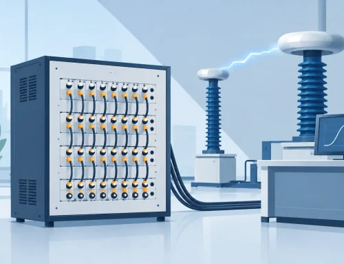
Multi-channel applications introduce another requirement: channel-to-channel timing. Measuring relative motion between two points, calculating runout, or assessing parallelism can require simultaneous or tightly synchronized sampling. Sequential data from independent channels may be acceptable for slow processes but misleading for dynamic ones. Confirm timing architecture before assuming that two channels can support differential or phase-sensitive measurements.
Calibration and Verification Should Be Built Into the Plan
A calibration certificate establishes traceability for a defined configuration at a point in time. It does not eliminate the need for application-level verification. Before releasing a system for production or formal test use, verify performance using an appropriate reference, such as a controlled displacement standard, qualified artifact, or known-good mechanical condition.
Verification intervals depend on risk, usage, environmental exposure, and required uncertainty. A research setup that is reconfigured frequently may need verification after every significant change. A fixed production station may benefit from a scheduled check using a stable artifact and documented acceptance limits. Any replacement of a sensor, cable, controller, mounting fixture, or target configuration should trigger a review of calibration validity.
For regulated or mission-critical work, retain the controller configuration with the measurement record. Range, bandwidth, filter selection, scaling, firmware revision, sensor serial number, and verification status can be as important as the final measured value when investigating an out-of-tolerance result.
A Practical Selection Path
When comparing noncontact sensor controllers, reduce the choice to evidence from the application. Confirm that the controller supports the required sensor and calibrated range. Then validate noise and stability against the smallest meaningful measurement, not only the catalog resolution. Confirm that bandwidth and filtering capture the relevant mechanical behavior, and verify that the interface and timing architecture fit the acquisition workflow.
Finally, assess supportability. In high-consequence environments, engineering assistance, calibration capability, configuration documentation, and availability of replacement components affect total measurement risk. Suppliers with application experience can help identify target-related effects and installation details before they become expensive troubleshooting work.
Vitrek and MTI Instruments systems are designed for applications where displacement data must remain credible from setup through final review. The most useful controller is not necessarily the one with the longest specification table. It is the one that produces repeatable, traceable results in the actual machine, fixture, and operating environment where engineering decisions are made.