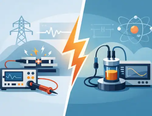
A few microns of apparent motion can be a real mechanical event, thermal growth, fixture compliance, cable noise, or a measurement artifact. That is why a capacitive sensor vs LVDT decision cannot be made from resolution specifications alone. Both technologies can deliver highly repeatable displacement data, but they measure motion differently and respond differently to materials, targets, environmental conditions, and electronics.
For test engineers, metrology teams, and machine designers, the right choice begins with the measurement objective. Is the task to characterize sub-micron motion on a conductive target? Measure actuator travel across a long stroke? Monitor a component inside a harsh industrial assembly? The sensor should be selected around the full uncertainty budget, not only the nominal measurement range.
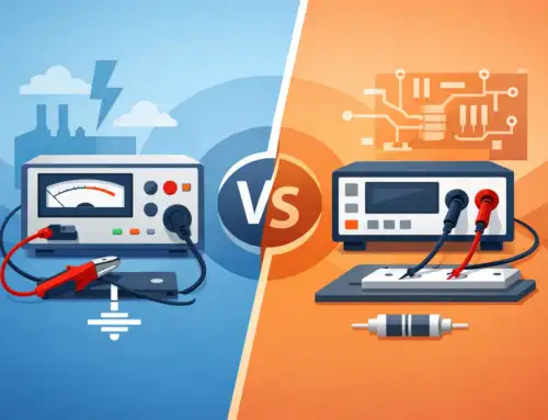
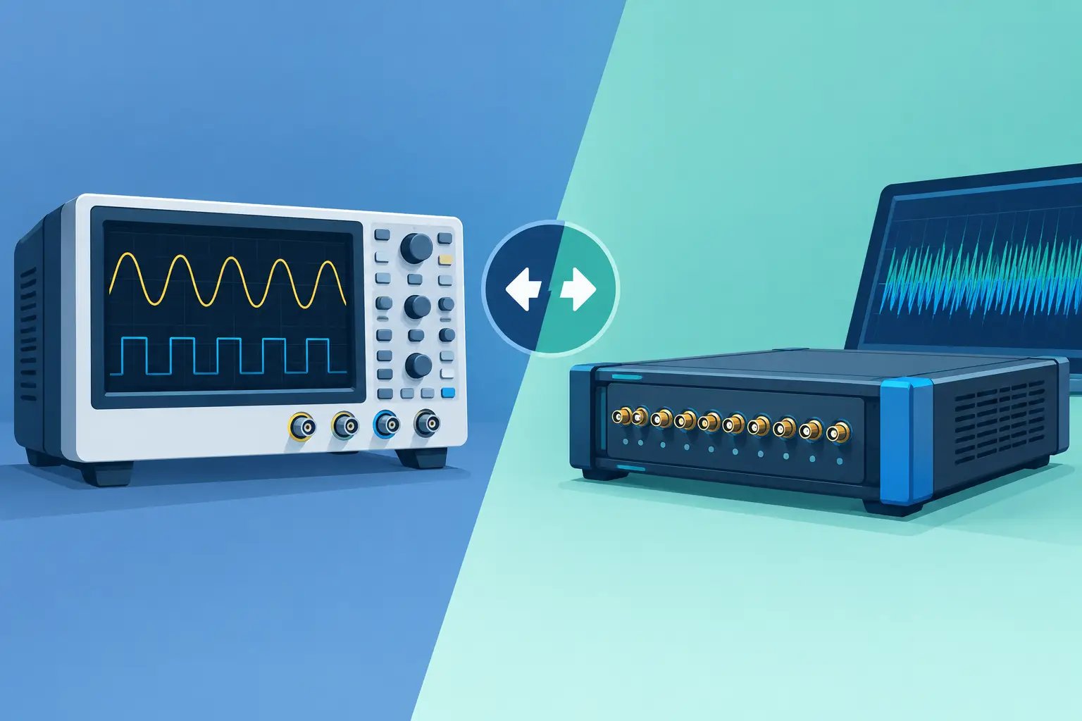
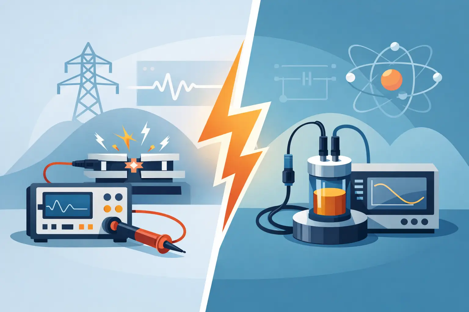
Capacitive Sensor vs LVDT: The Core Difference
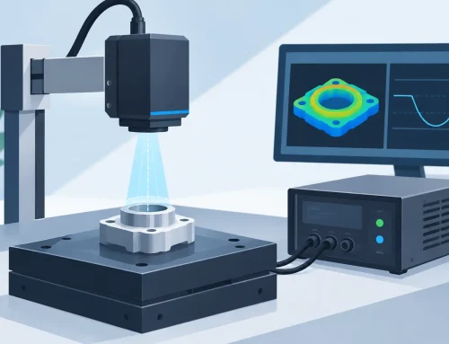
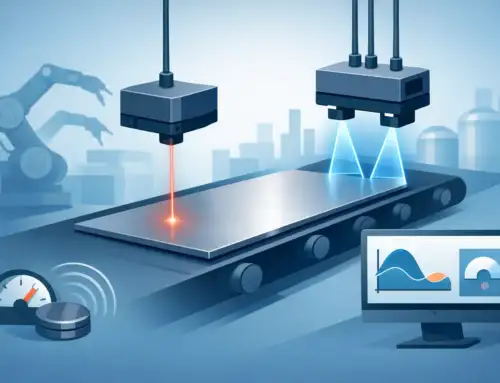
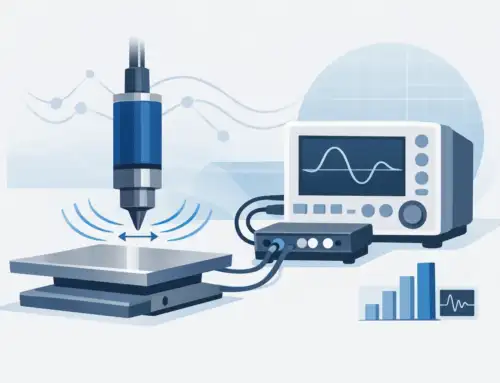
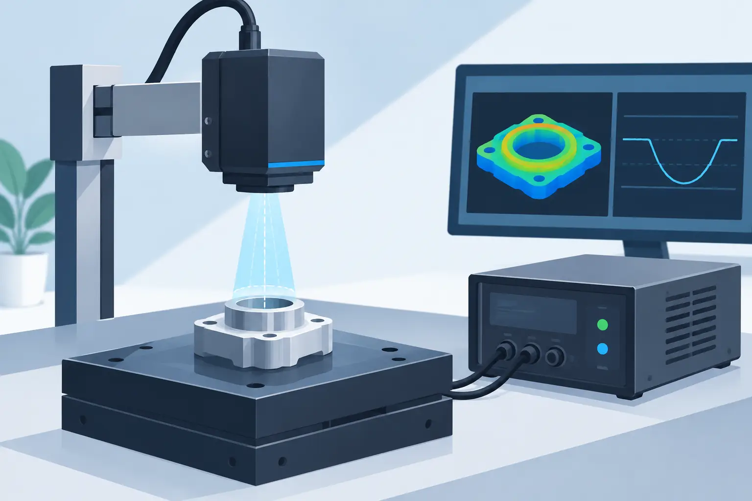
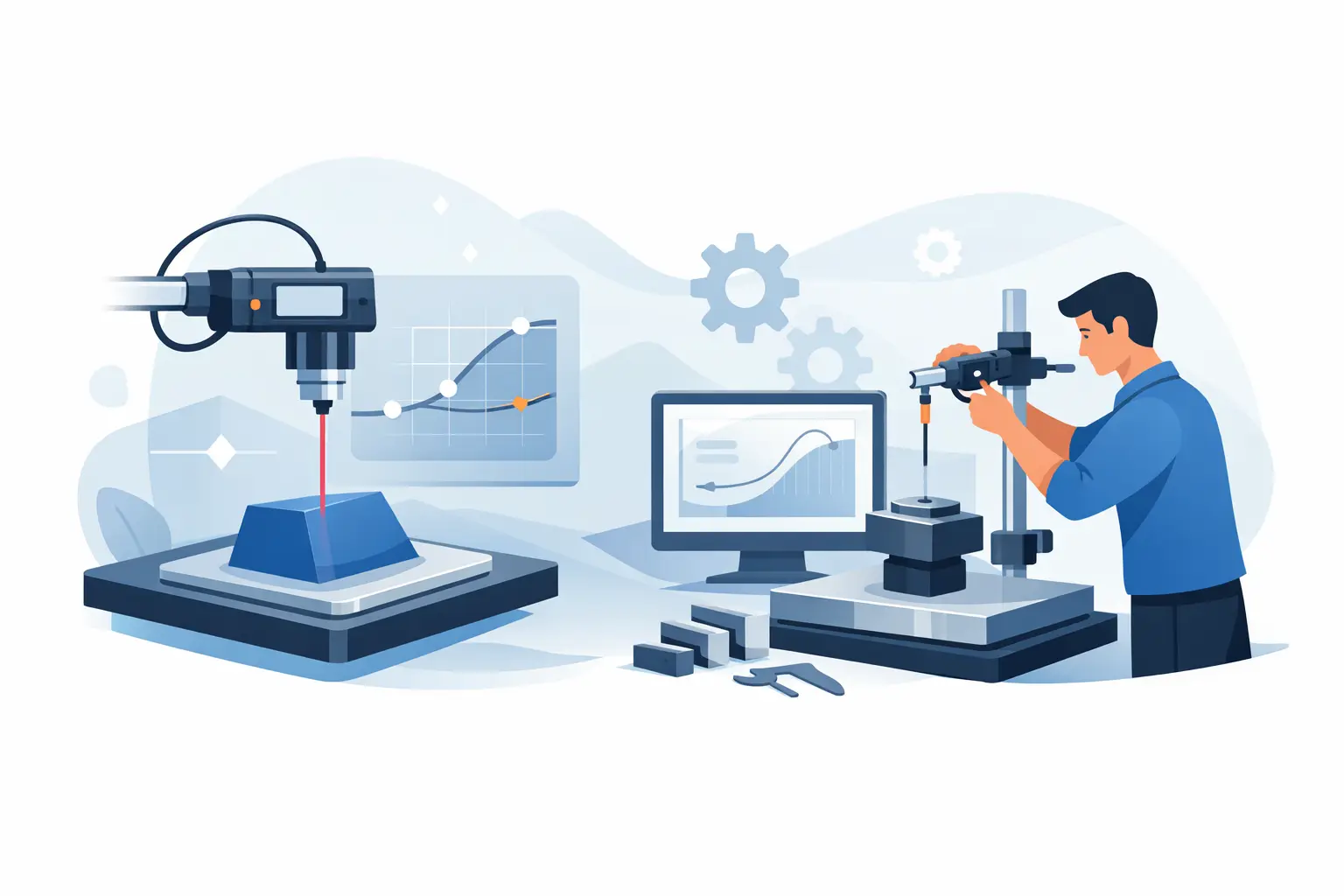
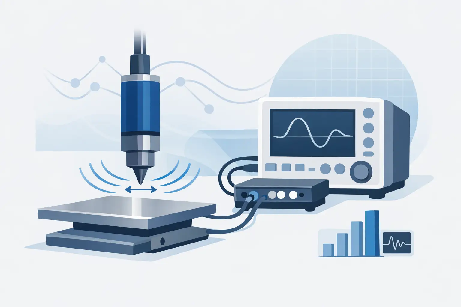
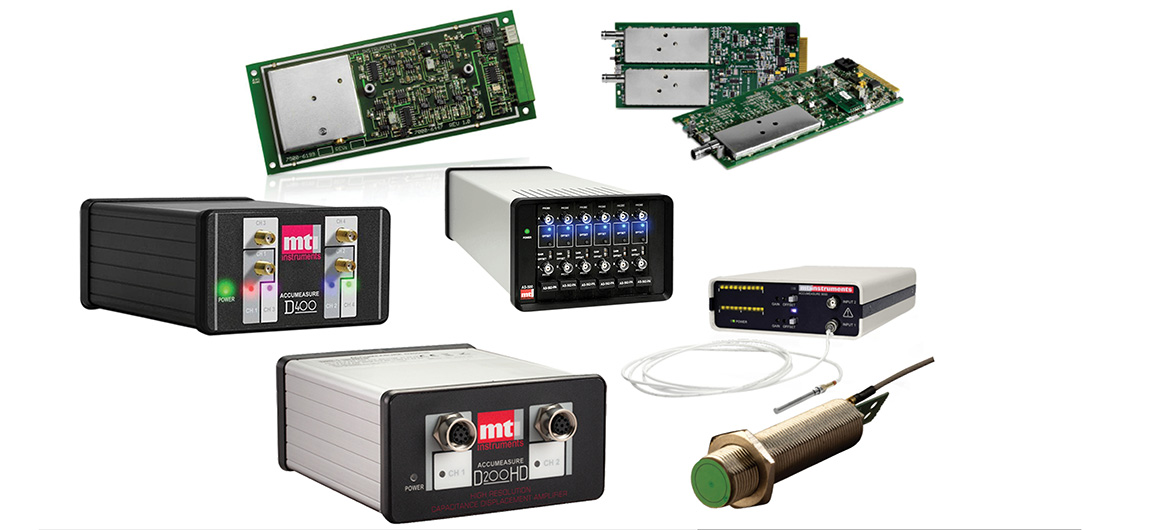
A capacitive displacement sensor measures the change in electrical capacitance between a probe and a target. As the gap changes, capacitance changes. The controller converts that change into a displacement measurement. Because the method is non-contact, it is particularly useful where probe force, friction, wear, or hysteresis from a contacting mechanism would compromise the result.
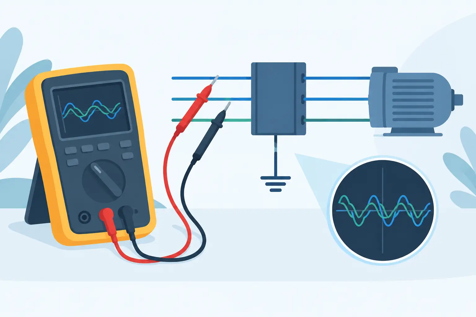
An LVDT, or linear variable differential transformer, uses a movable ferromagnetic core inside a transformer assembly. Motion of the core changes the coupling between a primary coil and two secondary coils. Signal-conditioning electronics interpret the differential output as position and direction. The core does not normally contact the coil assembly, but it must be mechanically coupled to the moving object being measured.
This distinction drives nearly every practical trade-off. Capacitive sensing measures the gap to a target surface. An LVDT measures the position of its core. A capacitive system is therefore sensitive to target properties and installation geometry. An LVDT is more dependent on mechanical alignment, core coupling, and the available physical envelope.
Where Capacitive Sensors Excel
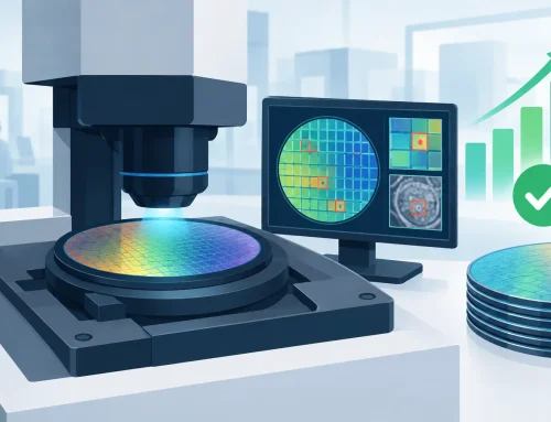
Capacitive sensors are often the preferred choice when the engineering requirement centers on very small displacement, high bandwidth, and non-contact measurement. They are widely used for spindle runout, vibration, wafer positioning, precision stage control, shaft motion, and surface characterization.
Resolution can be extremely fine when the sensor, controller, target, cabling, and environment are properly matched. Their fast response also makes them well suited to dynamic measurements that would be blurred by a lower-bandwidth transducer or a mechanically loaded probe. In a vibration study, for example, the ability to capture small, rapid changes in gap can be more valuable than a long measurement stroke.
The target must be considered part of the measurement system. Conductive targets are typically required, and target material can affect calibration and sensitivity. Surface finish, curvature, thickness, grounding, and nearby conductive structures may also influence results. A sensor calibrated on a flat aluminum target should not be assumed to produce the same accuracy on a curved steel surface without verification.
Capacitive sensors also require disciplined mechanical installation. Tilt between the probe face and the target, changes in nominal gap, and variations in target area can introduce error. In tightly controlled metrology setups, these conditions can be managed effectively. In production equipment with changing fixtures, contamination, or loosely controlled target geometry, the integration effort may outweigh the sensor’s resolution advantage.
Where LVDTs Excel
LVDTs are established workhorses for industrial displacement measurement. They provide excellent repeatability, a broad selection of measurement ranges, and a measurement principle that is generally less sensitive than capacitive sensing to the electrical characteristics of the measured object. The moving item need not be conductive because the LVDT measures core position rather than target capacitance.
This makes LVDTs useful for valve position, actuator travel, suspension and structural testing, hydraulic equipment, machine control, and long-stroke dimensional measurements. When a test fixture already includes a pushrod, linkage, or moving shaft, coupling an LVDT core to that mechanism can be straightforward and dependable.
An LVDT can tolerate demanding service conditions when the selected model, housing, connector system, and signal conditioning are appropriate for the application. Its non-contact internal operating principle also avoids the sliding electrical contacts found in potentiometric position sensors. For applications that need millions of cycles, this is a meaningful reliability advantage.
There are limits. The core must move along the sensor axis with sufficient clearance. Side loading, poor coupling, excessive core misalignment, and mechanical backlash in the attachment hardware can degrade the measurement. LVDTs also require excitation and demodulation electronics, and performance depends on the compatibility of the transducer and conditioner. A low-noise, properly calibrated signal chain is essential when the application calls for high accuracy.
Comparing Range, Resolution, and Bandwidth
Capacitive sensors usually hold the advantage for short-range, ultra-fine displacement measurements. Their usable range is commonly limited compared with many LVDTs, but their ability to resolve minute gap changes makes them valuable in precision metrology. The meaningful question is not simply whether a controller reports nanometer-level resolution. It is whether the complete installed system can achieve the required noise floor and uncertainty under actual operating conditions.
LVDTs are often the stronger option as stroke length increases. They can measure motion from small fractions of an inch to several inches or more, depending on the design. Their resolution may be very good, but it is generally evaluated in the context of the signal conditioner, data acquisition system, vibration environment, and mechanical coupling.
Bandwidth should be assessed at the system level as well. Capacitive systems can support very fast dynamic measurements, provided the controller and acquisition hardware have adequate bandwidth and the installation does not introduce vibration artifacts. LVDT response can also support dynamic testing, but its usable frequency response depends on the transducer design, carrier frequency, conditioning method, and moving-mass arrangement.
Environmental and Integration Factors
The sensor’s environment often decides the selection before the accuracy specification does. Capacitive sensing can be affected by moisture, contamination, dielectric changes, electromagnetic interference, and unstable grounding. A clean laboratory setup and a production cell exposed to coolant mist are not equivalent applications, even if the nominal displacement range is identical.
LVDTs may be better suited to applications where conductive target consistency cannot be guaranteed, but they introduce mechanical integration requirements. The sensor body needs a stable mount, the core requires controlled travel, and the coupling arrangement must not add friction or lost motion. If the measured mechanism is compliant, the attachment itself can become part of the error budget.
Temperature also deserves careful treatment. Thermal expansion may change the gap in a capacitive measurement or shift the relative position of an LVDT body and core. Electronics can drift, cables can move, and fixtures can grow. For precision work, specify the operating temperature range, allow stabilization time, and establish calibration practices that are traceable to the required quality system.
A Practical Selection Method
Start by defining the measurand in physical terms. If the requirement is the gap between a probe and a conductive surface, capacitive sensing measures that quantity directly. If the requirement is the linear travel of an actuator or mechanism, an LVDT may measure it more naturally through direct core coupling.
Next, establish the full operating range, required uncertainty, and frequency content. Include the normal operating position, not only the maximum excursion. A capacitive probe may need a controlled nominal gap, while an LVDT should operate within its specified linear region. Then evaluate target material, available mounting space, environmental exposure, cable routing, grounding, and maintenance access.
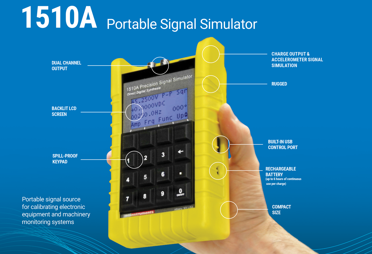
Finally, validate the proposed system on representative hardware. Measure repeatability over temperature, verify performance across the expected range, and test under actual vibration and electrical-noise conditions. For high-consequence programs, the sensor evaluation should include the controller, cabling, mounting hardware, data acquisition path, and calibration method. Suppliers such as Vitrek and its MTI Instruments portfolio can support this type of application-level assessment for precision displacement and metrology work.
The most useful sensor is the one that measures the required physical quantity with known uncertainty after it is installed, calibrated, and exposed to the conditions your product will actually see. Treat that installed performance as the acceptance criterion, and the capacitive-versus-LVDT choice becomes far clearer.