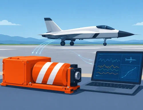
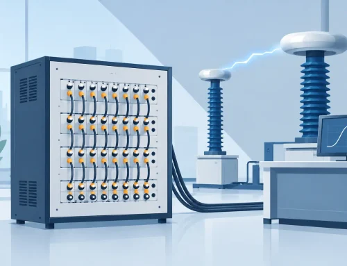
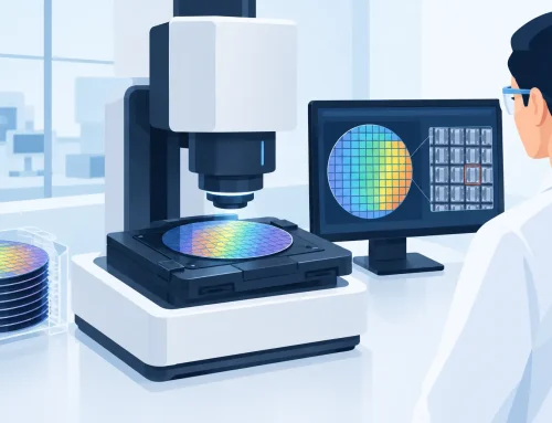
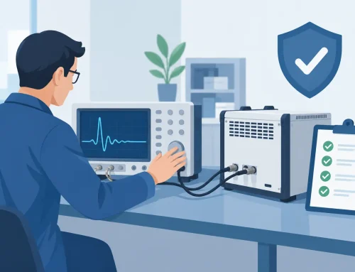
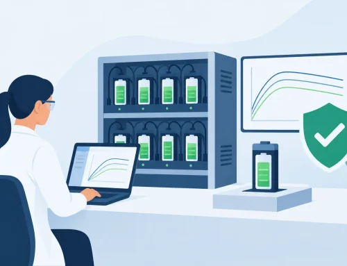
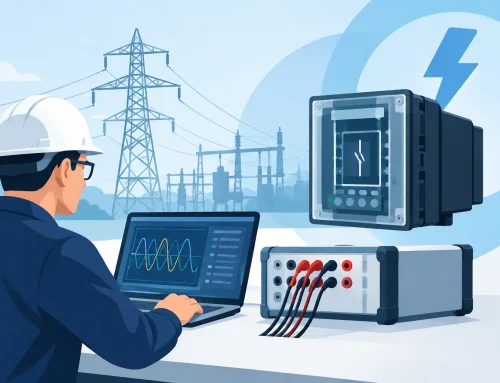
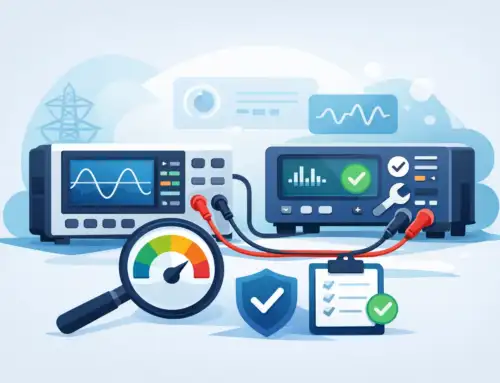
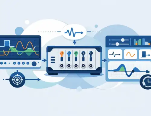
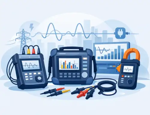
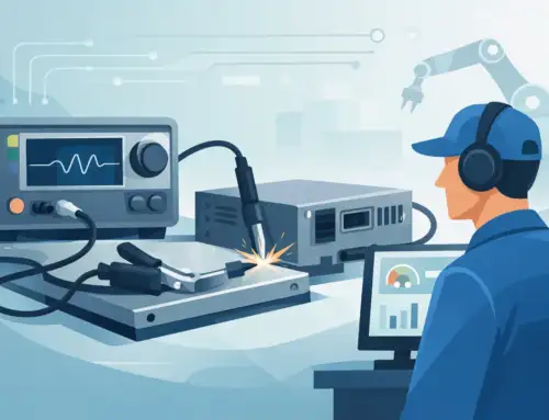
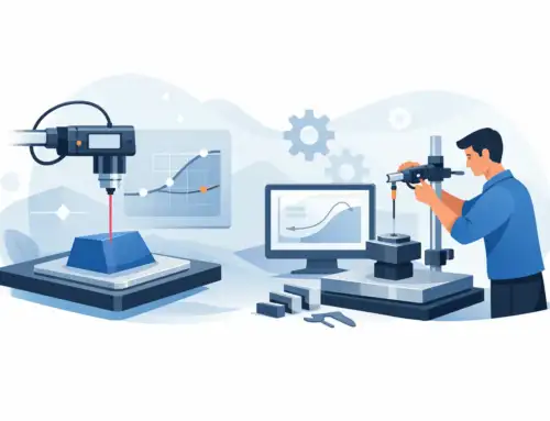
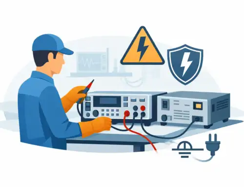
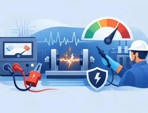
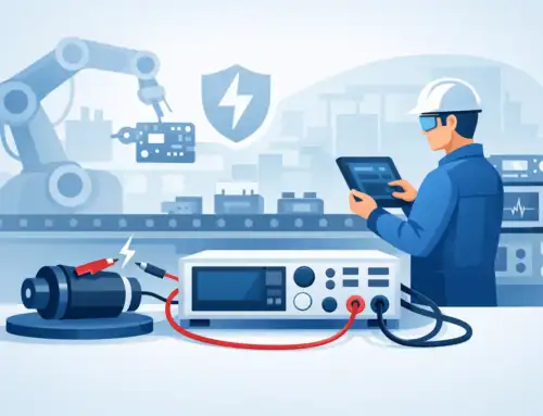
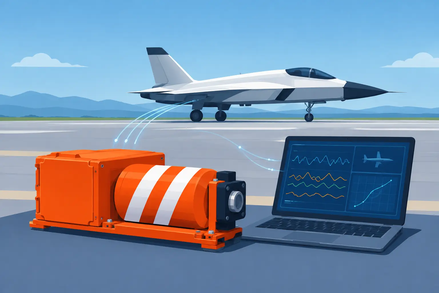
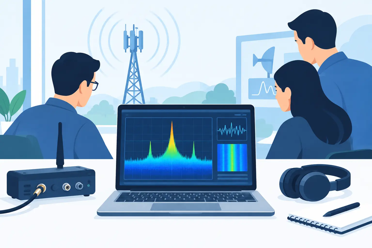
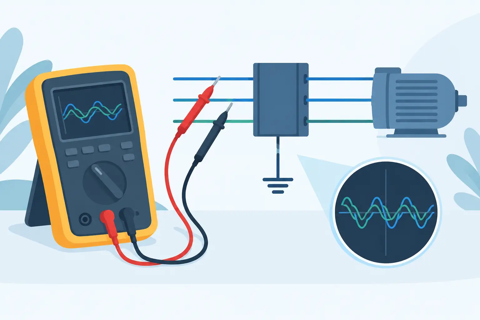
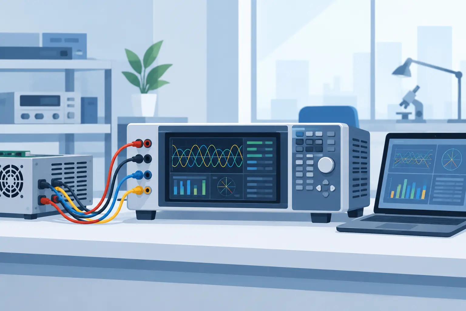
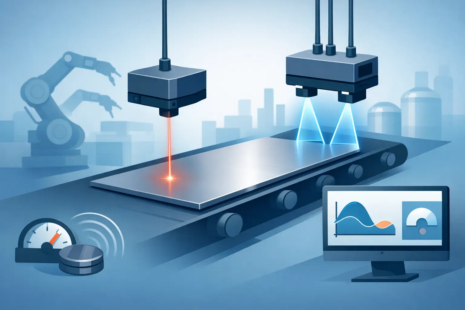
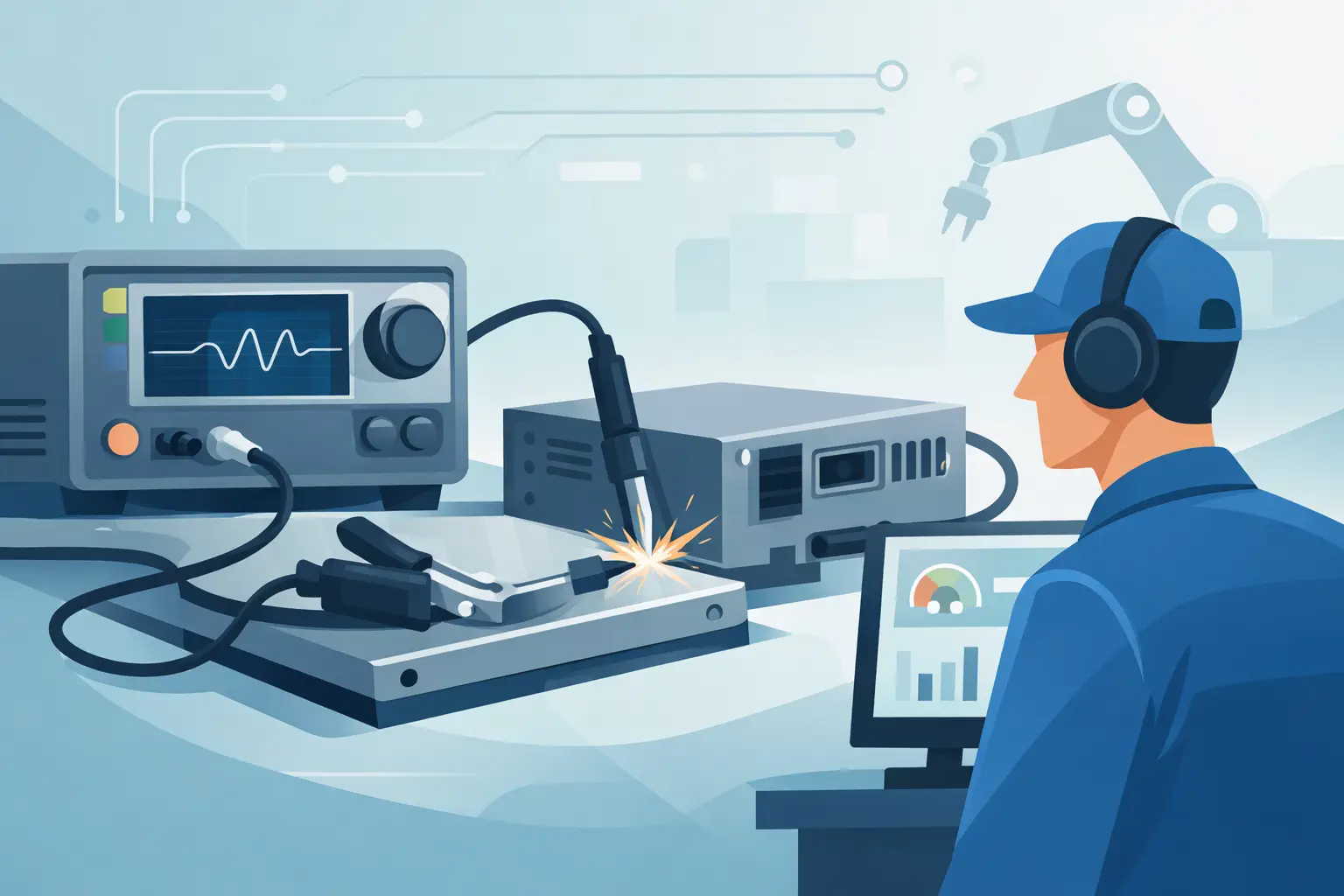
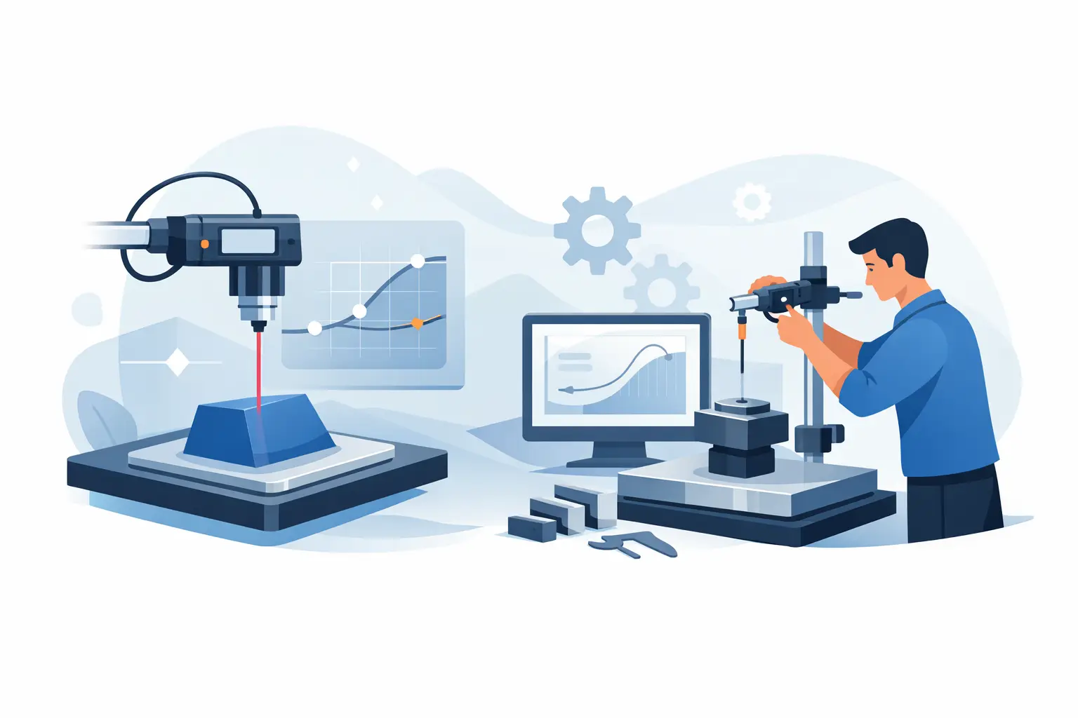
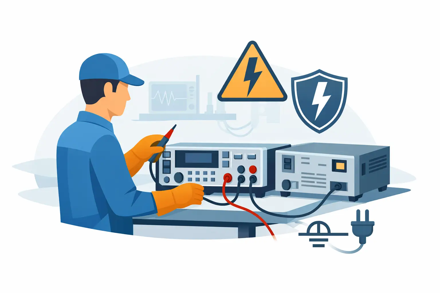
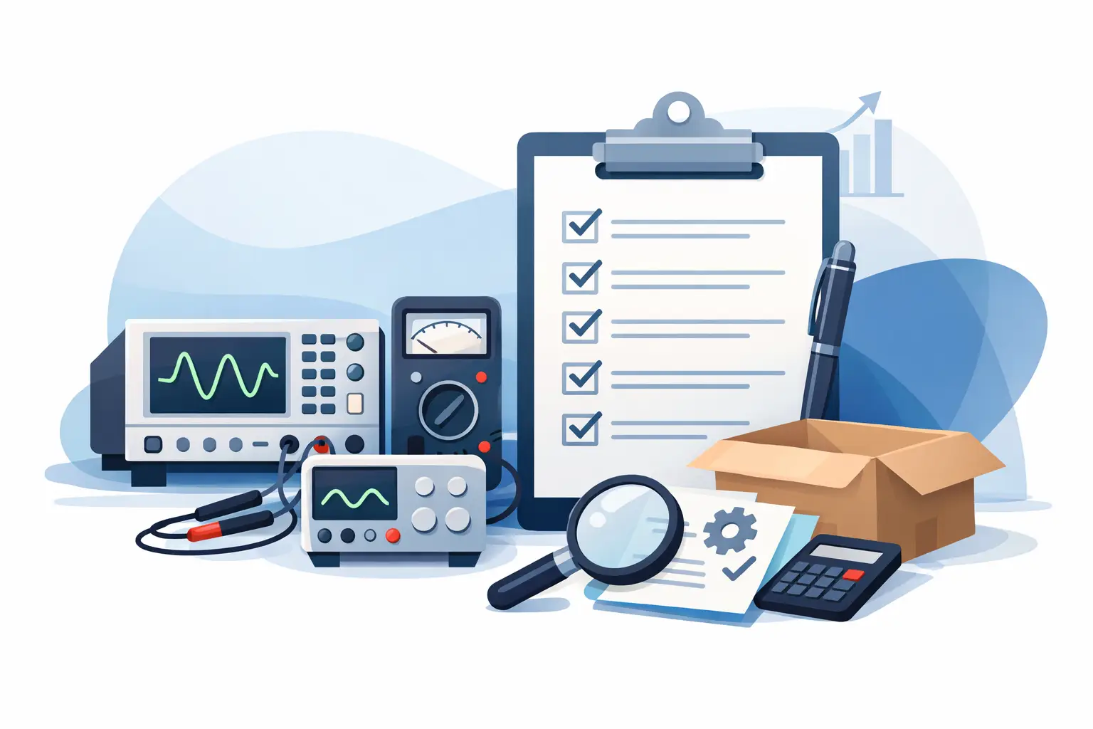
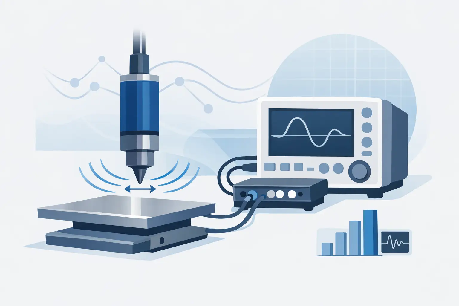
A data acquisition chassis review should begin with the measurement problem, not the chassis specification sheet. In a mixed-signal validation rack, an aerospace environmental test cell, or a production end-of-line station, the chassis determines whether digitizers, I/O modules, timing resources, and host software operate as one coherent system. A low initial chassis cost has little value if it introduces clock drift, slot restrictions, thermal limits, or a support burden that compromises measurement confidence.
For engineers responsible for repeatable results, the correct chassis is infrastructure. It affects channel density, synchronization accuracy, data movement, serviceability, and the practical life of the test system. The right selection depends on the acquisition architecture and the consequences of a missed event, an uncertain timestamp, or a system outage.
Start the Data Acquisition Chassis Review With the Application
The first question is not how many slots are available. It is what must be measured, at what rate, and with what timing relationship between channels. A chassis supporting occasional low-speed sensor readings has fundamentally different requirements from one collecting transient voltage, current, vibration, or RF data across multiple synchronized digitizers.
Define the required sample rate and record length per channel, then calculate the sustained data rate for the full configuration. Include overhead for triggering, timestamping, buffering, processing, and storage. A system can meet an individual module’s published sample-rate figure while failing to transfer or preserve data at the aggregate rate required by the application.
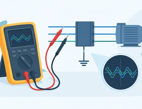
Timing requirements deserve the same discipline. Determine whether channels only need to start together, remain phase-aligned over long acquisitions, share a common trigger, or correlate with equipment outside the chassis. These are different requirements. A common trigger can establish event alignment, but it does not necessarily provide the clock quality needed for phase-sensitive power, vibration, radar, or communications measurements.
Also consider how the system will evolve. A prototype setup may begin with two digitizer channels and later require synchronized expansion, stimulus control, switching, or sensor inputs. A chassis with unused capacity is not automatically a better choice, but a platform that can grow without changing software, timing architecture, or calibration practices can reduce revalidation work.
Backplane Bandwidth Is a System-Level Limit
The backplane is the data path shared by installed modules. Its performance must be evaluated against sustained, simultaneous traffic, not only peak transfer figures quoted for a single slot. High-speed acquisition systems frequently encounter a bottleneck between the module’s onboard memory and the host computer, particularly when multiple channels stream continuously.
Review the bus generation, lane allocation, slot topology, and controller connection. Some chassis architectures provide equal performance to every slot, while others use shared switching resources or segment bandwidth across groups of slots. These differences matter when placing high-throughput digitizers next to storage, FPGA, or communication modules.
Host connection is equally consequential. PCI Express expansion, Ethernet-based control, or embedded controllers each introduce different bandwidth, latency, and deployment considerations. A remote chassis may simplify placement near the unit under test, but the network path must support the required data rate and tolerate the operating environment. For sustained high-speed capture, it is prudent to validate the complete chain: acquisition module, chassis fabric, controller interface, host memory, processing load, and storage subsystem.
Short burst captures can often rely on onboard memory followed by transfer after the event. Continuous recording cannot. Treat these as separate use cases during evaluation.
Synchronization Is More Than a Trigger Connection
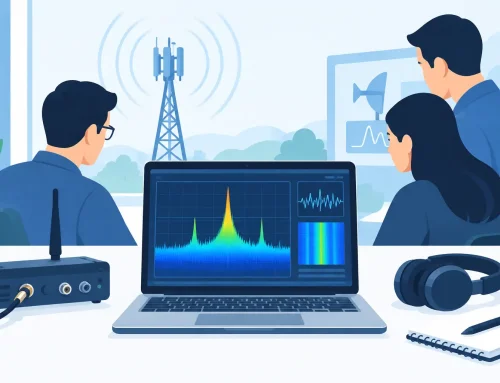
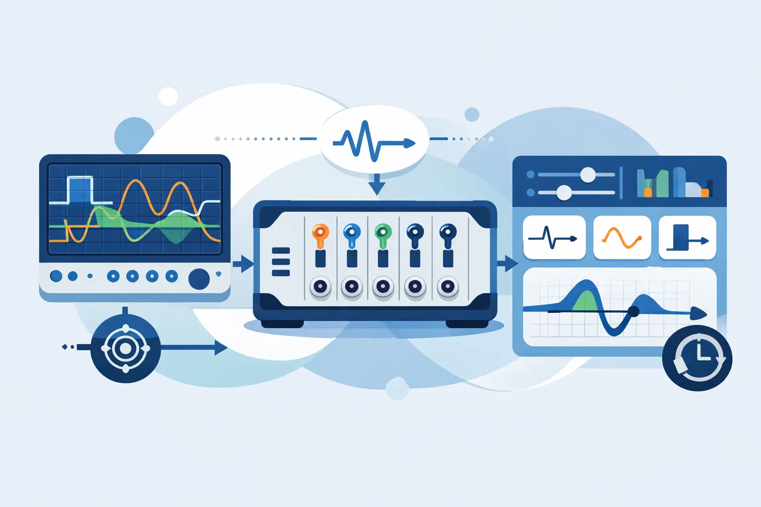
A credible chassis review examines how timing is distributed, conditioned, and verified. Look for support for a shared reference clock, star-trigger or equivalent low-skew trigger routing, external reference inputs and outputs, and a documented synchronization method across multiple chassis where required.
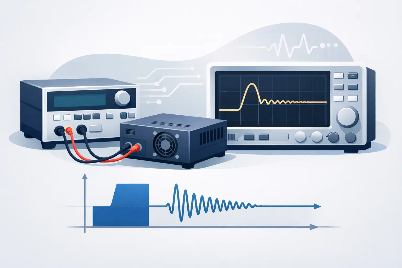
Clock quality affects more than sample timing. Jitter can reduce effective dynamic performance in high-frequency measurements, while drift can impair correlation across lengthy acquisitions. The significance depends on signal frequency, acquisition duration, and analysis method. For slowly changing temperature or pressure channels, timing error may be secondary. For transient capture, modal analysis, rotating machinery diagnostics, or phase measurements, it can become a primary source of uncertainty.
The chassis should also support a practical timing architecture. Engineers need clear access to trigger lines and clock resources without consuming excessive front-panel connections or creating fragile external cabling. In complex systems, documented routing behavior and software visibility into synchronization status are valuable because they simplify troubleshooting during acceptance testing and later maintenance.
Thermal Design and Mechanical Construction Affect Measurement Integrity
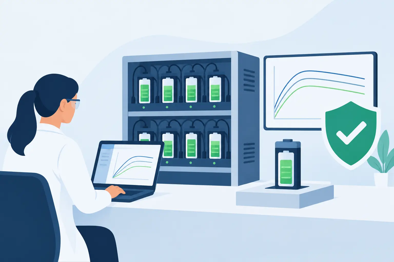
A chassis is often evaluated in a lab at partial slot population, then deployed fully loaded in a rack where ambient temperature, airflow restrictions, and adjacent equipment change the operating conditions. That is where cooling design becomes an engineering requirement rather than a convenience feature.
Review the allowed operating temperature, airflow direction, fan control, filtration approach if applicable, and derating guidance for fully populated systems. Confirm that high-power modules can coexist in their intended slot positions. A chassis may need spacing rules, blank panels, or limits on adjacent module types to maintain safe internal temperatures.
Thermal instability can produce intermittent failures, accelerated component aging, and measurement drift. Fan noise may also matter in acoustic or laboratory environments, while fan serviceability matters in systems expected to remain in operation for years. Rack depth, rail support, cable strain relief, shock and vibration exposure, and grounding provisions should be reviewed with the same care. The mechanical enclosure is part of the test system, especially in mobile, defense, manufacturing, and environmental test applications.
Software Compatibility Determines Daily Usability
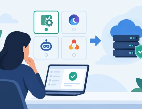
Hardware capability only becomes useful when the control and acquisition environment is stable. Verify operating-system support, driver maturity, programming interfaces, sample applications, and compatibility with the organization’s preferred development environment. An SDK should give engineers access to triggering, clock configuration, calibration data, diagnostics, and error reporting rather than limiting them to basic acquisition commands.
For automated test systems, assess whether the software model supports deterministic startup, configuration storage, module discovery, and recovery after power interruptions. In regulated or high-consequence applications, configuration control and traceability can be as important as display features. Teams should be able to record firmware versions, driver versions, chassis serial numbers, module locations, and calibration status as part of their test documentation.
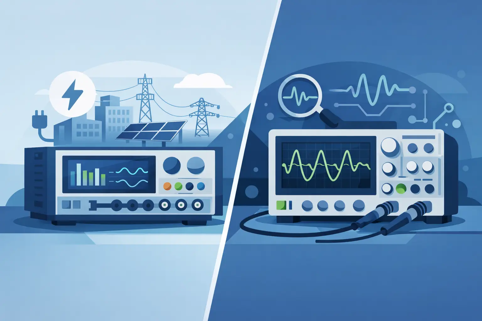
Interoperability is another practical consideration. A mixed system may combine high-speed digitizers with precision power instruments, switching hardware, safety test equipment, or custom fixtures. The best chassis architecture is not always the one with the most features. It is the one that integrates cleanly with the required instruments and produces data that can be trusted, reviewed, and retained.
Serviceability and Lifecycle Support Belong in the Decision
A data acquisition chassis is commonly deployed for far longer than the development project that selected it. Before standardizing on a platform, examine the availability of spare parts, repair capability, calibration implications, firmware policy, and expected product lifecycle. Ask how a failed power supply or fan assembly is handled, whether field replacement is supported, and whether a replacement chassis will preserve timing and software behavior.
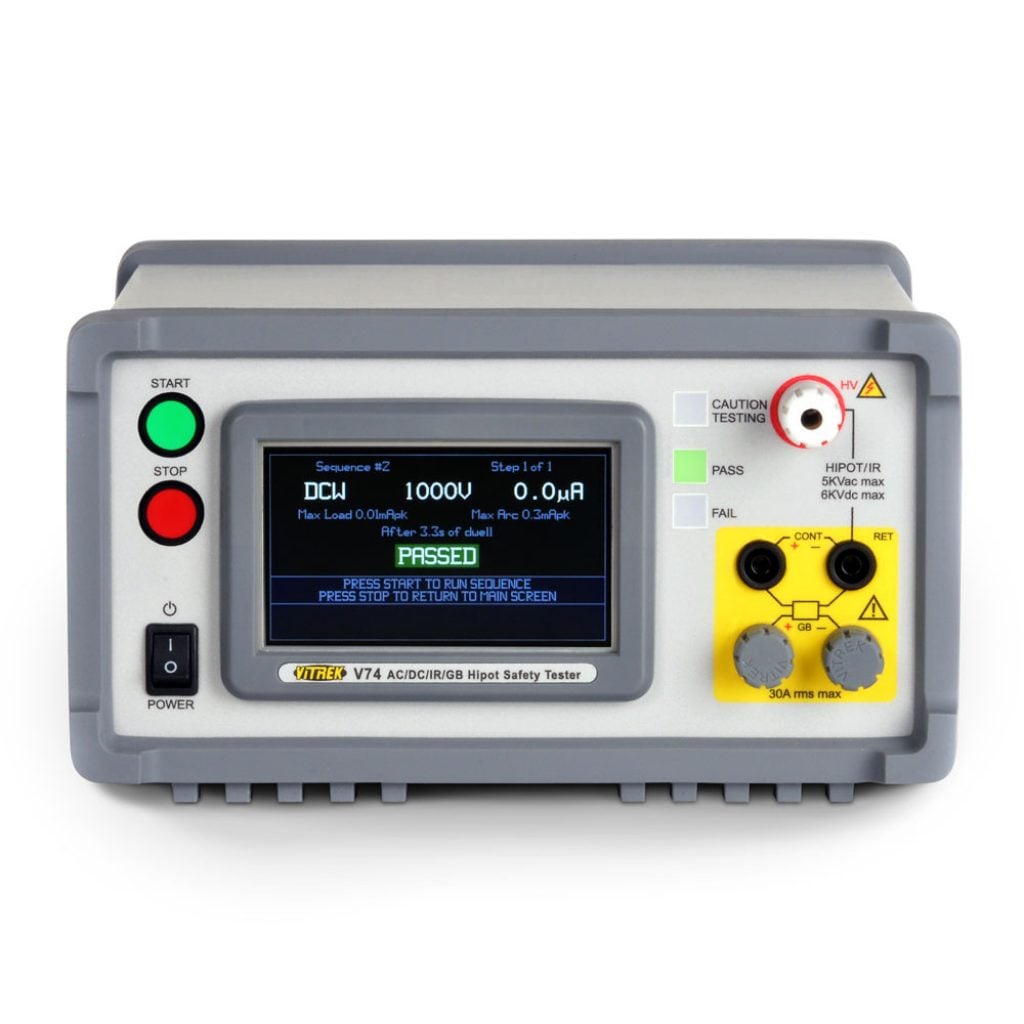
For organizations operating formal quality systems, vendor documentation and support responsiveness are operational requirements. Manufacturers with application expertise can help resolve issues involving slot loading, timing distribution, digitizer configuration, and system-level performance before those issues reach production. Vitrek’s measurement portfolio is particularly relevant where high-speed data capture must coexist with precision electrical, safety, or diagnostic test functions.
A Practical Acceptance Test Before Deployment
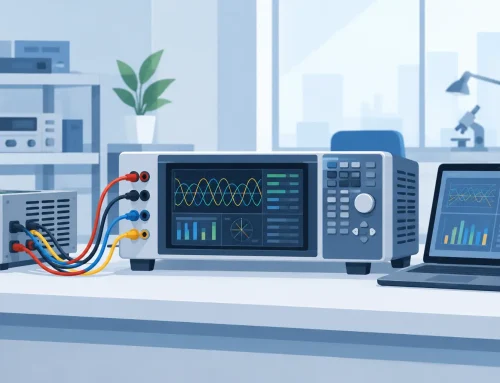
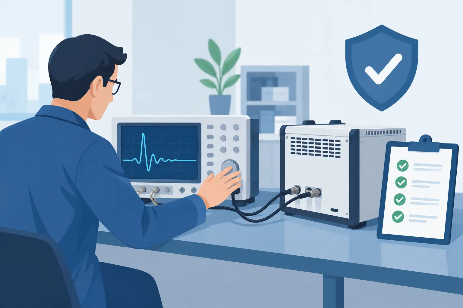
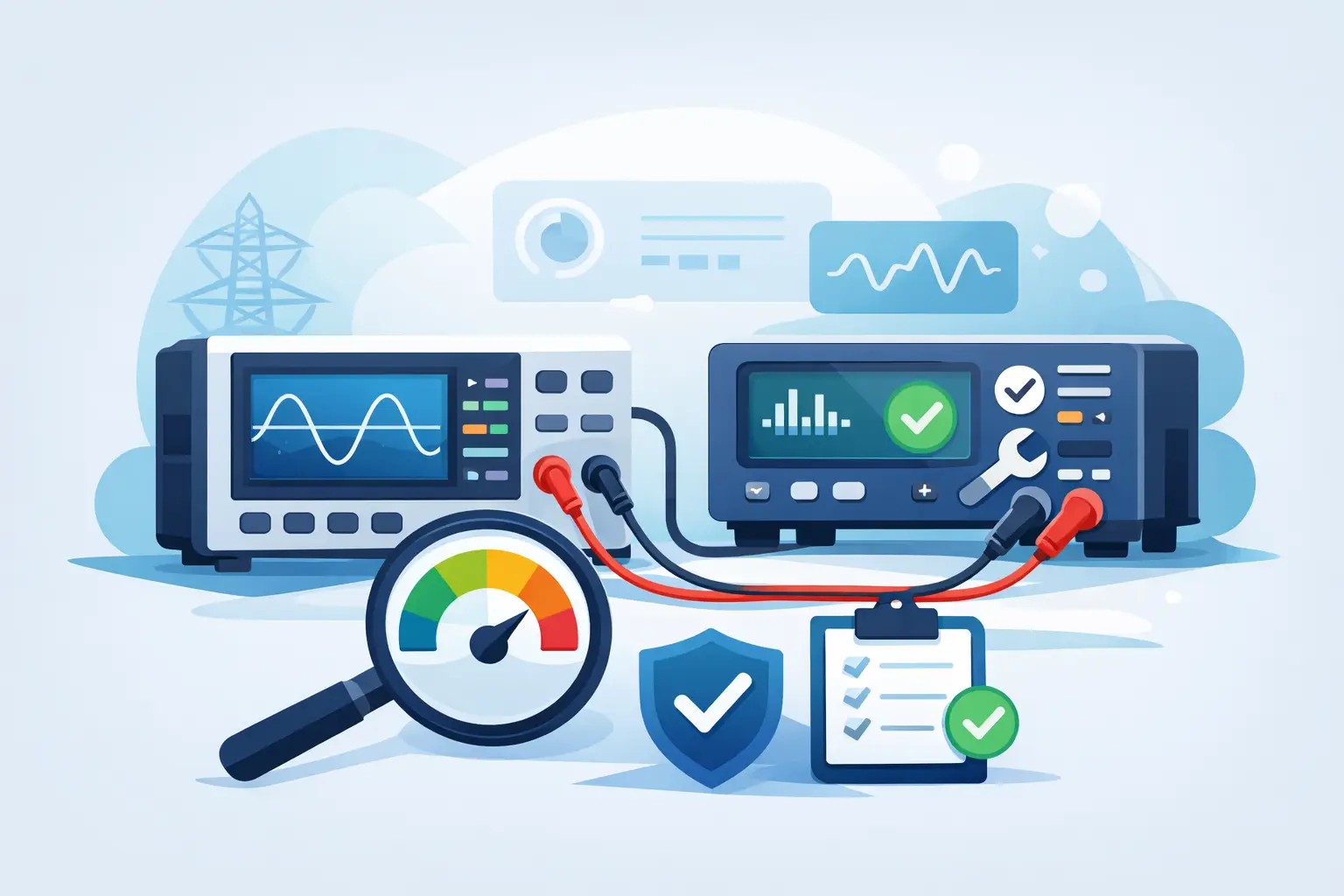
A chassis should be tested as a populated system, not accepted on the basis of module-level specifications alone. Run the intended channel count at the required sample rate and acquisition duration. Confirm trigger repeatability, clock synchronization, sustained transfer performance, temperature behavior, host CPU utilization, and recovery after controlled interruptions.
Where timing accuracy is critical, use a known reference signal to measure interchannel skew and long-duration alignment. Where continuous streaming is required, record long enough to expose buffer exhaustion, storage limitations, or thermal effects. Repeat the test with the actual cables, fixtures, software release, and environmental conditions planned for deployment.
The chassis that earns approval is the one that preserves the measurement chain under real operating conditions. That standard keeps the selection focused where it belongs: on defensible data, repeatable tests, and a system engineers can support with confidence years after installation.