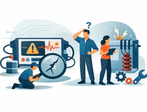
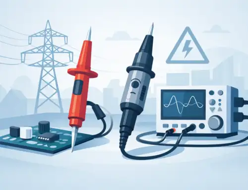
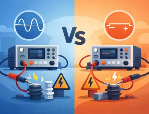
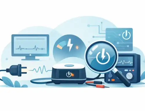
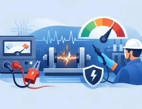
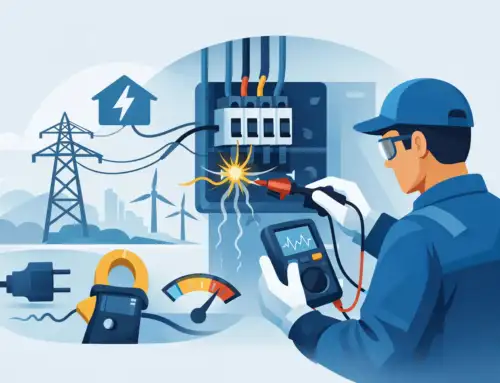
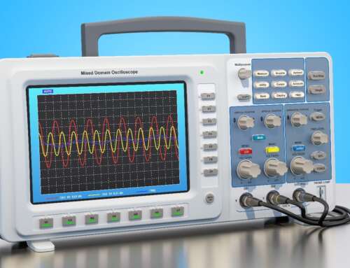
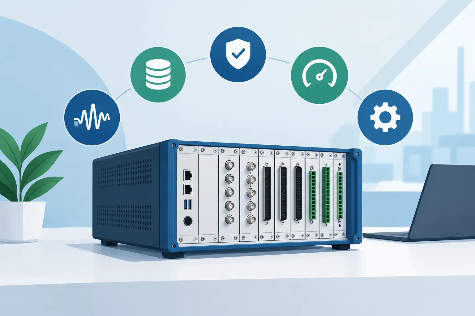
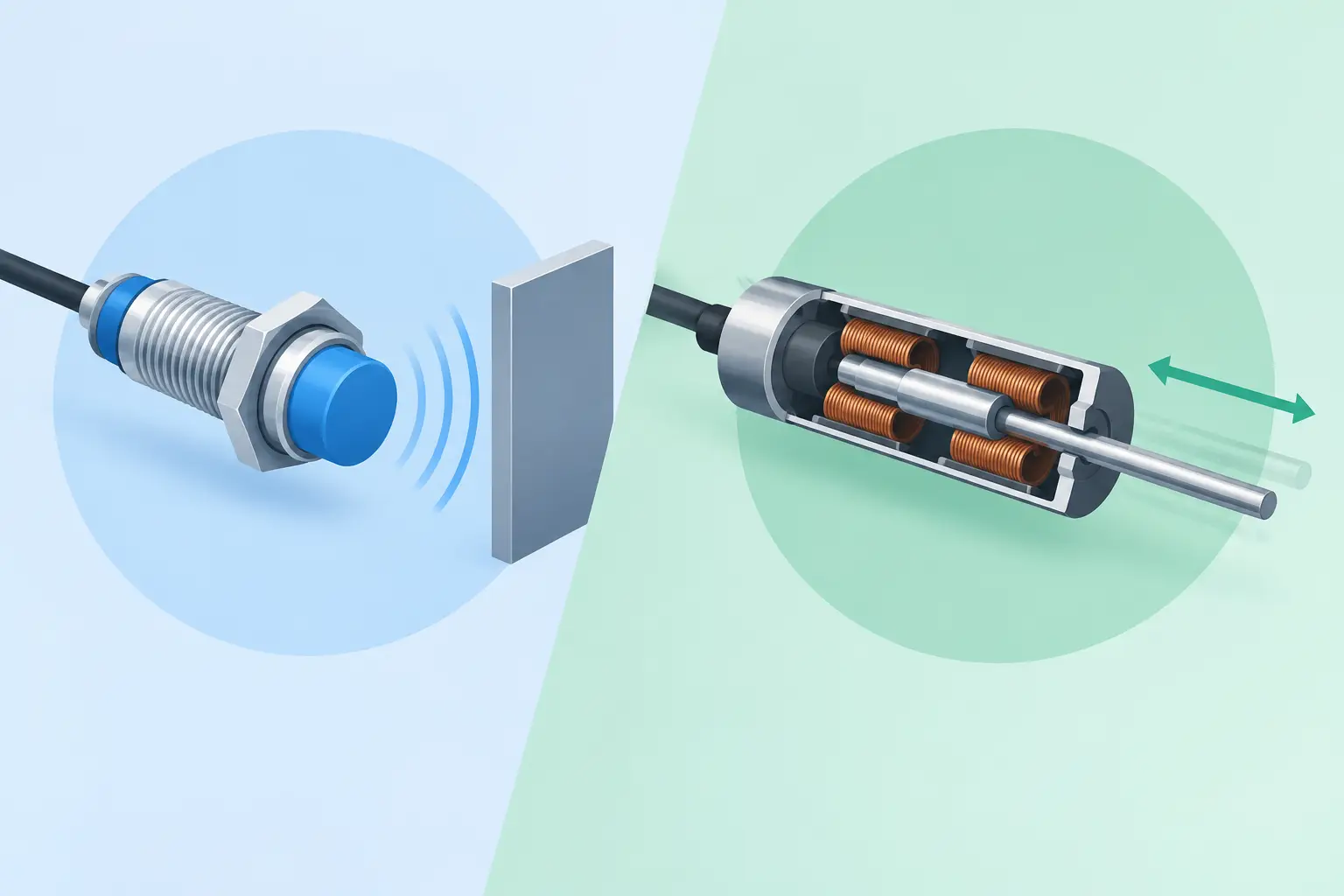
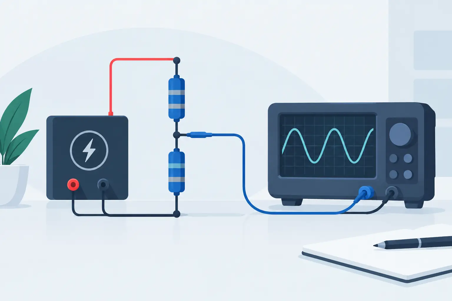
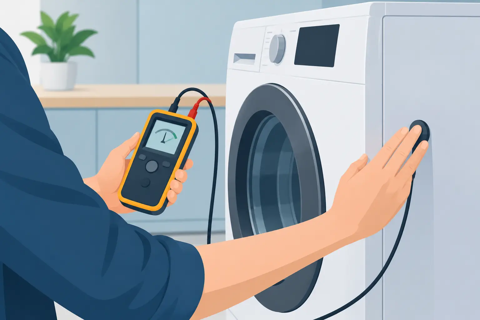
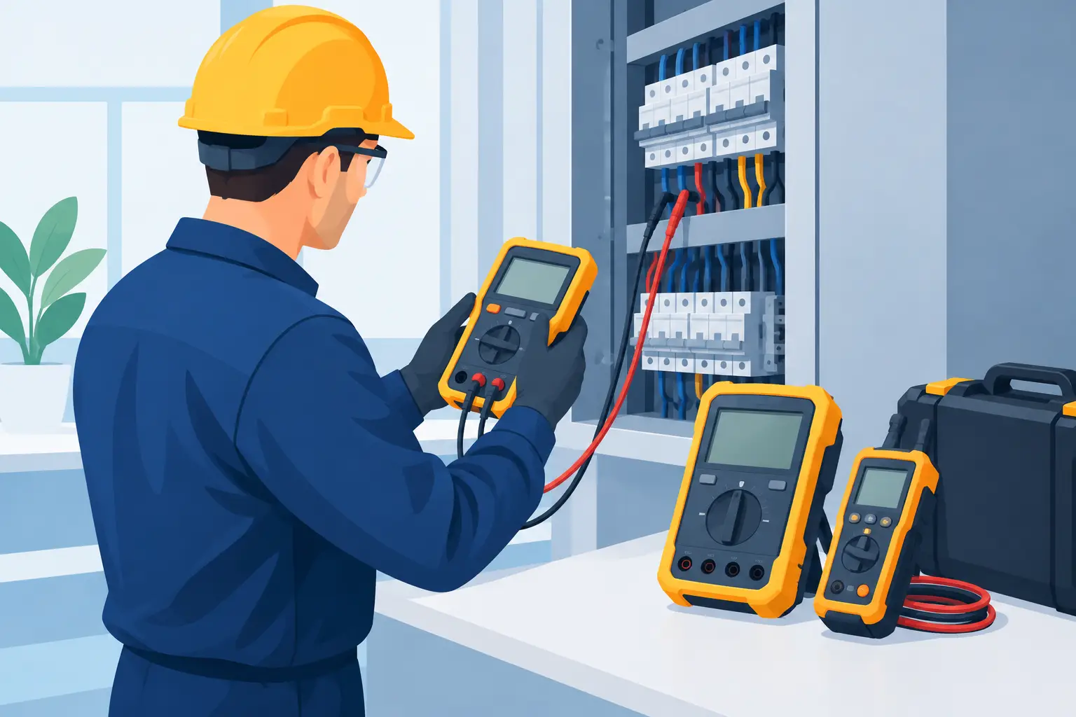
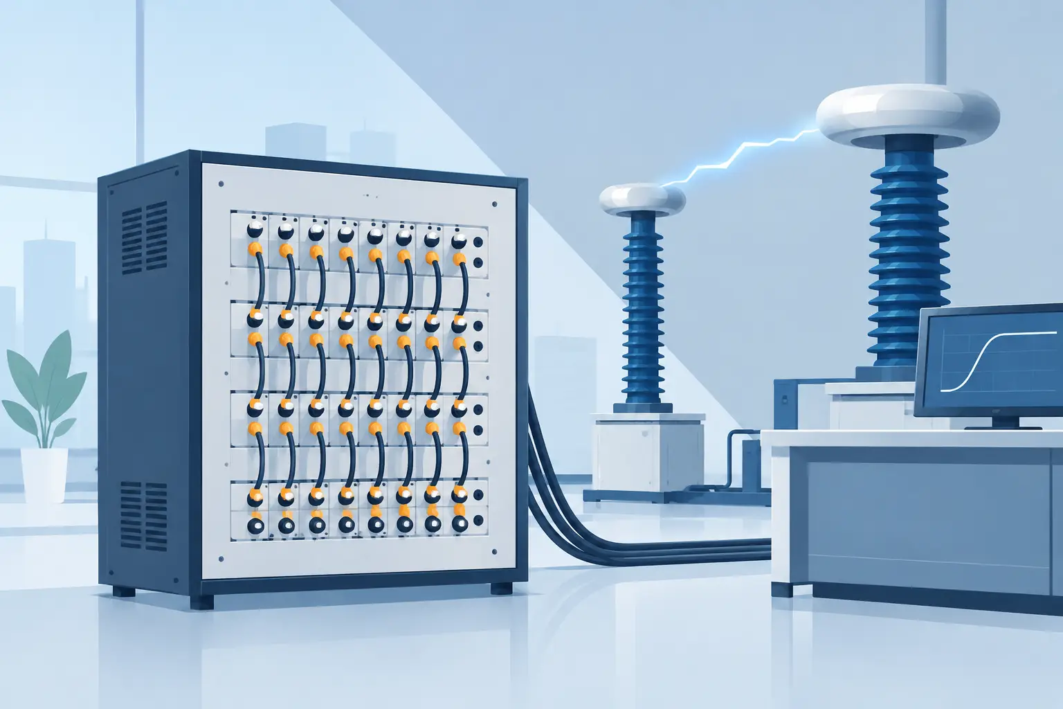
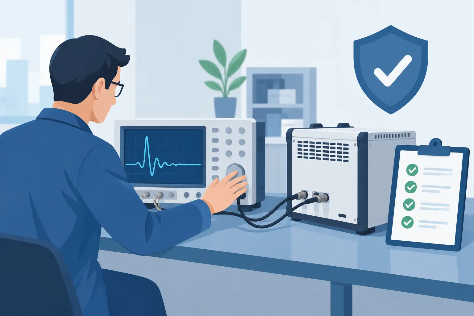
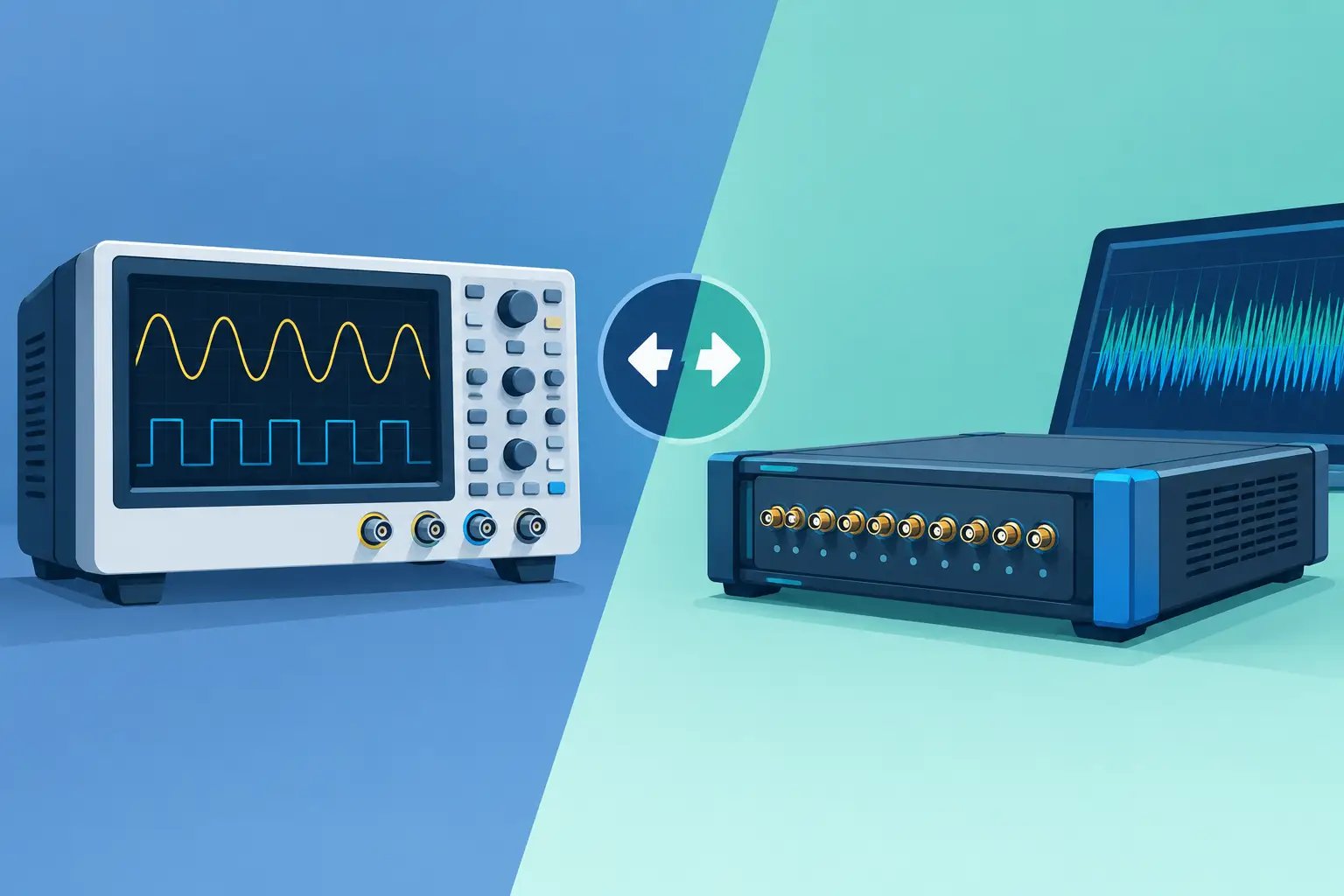
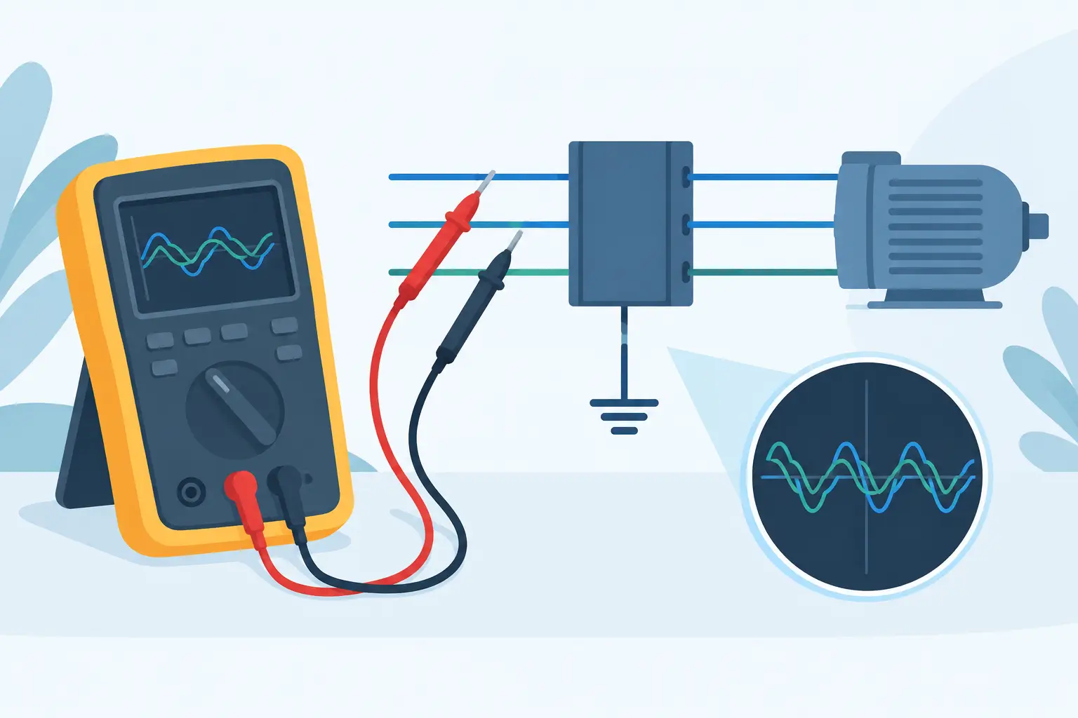
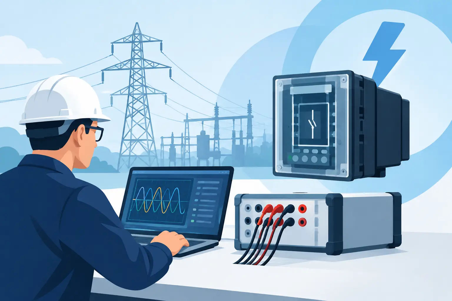
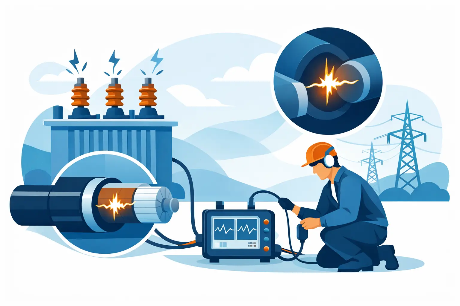
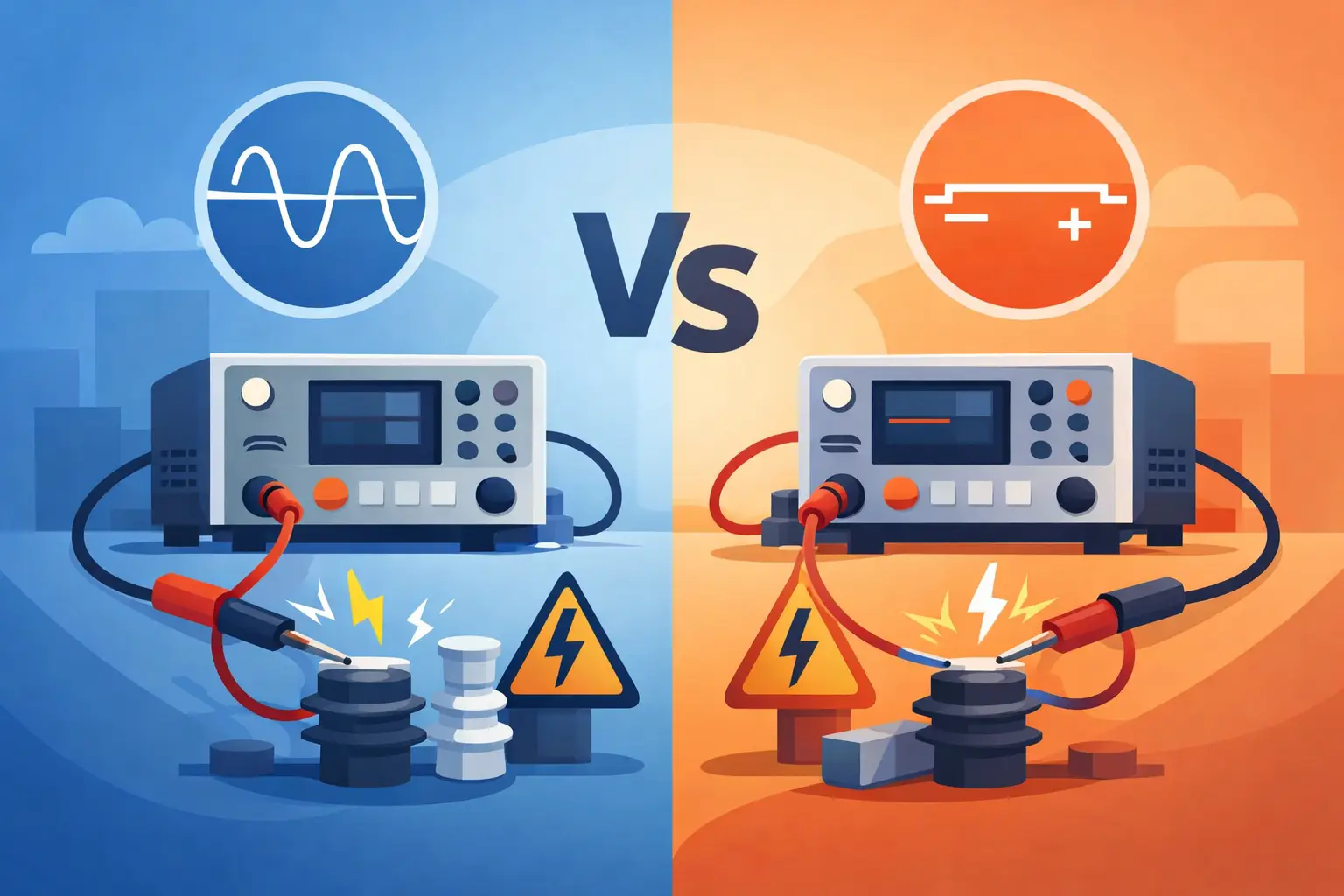
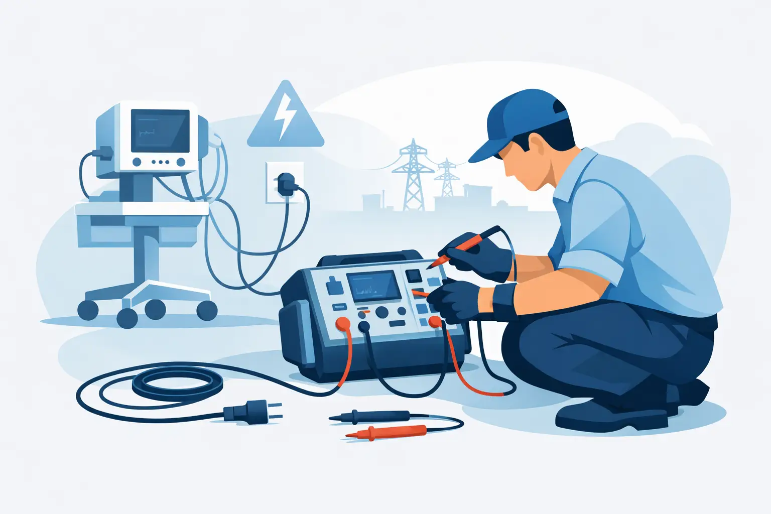
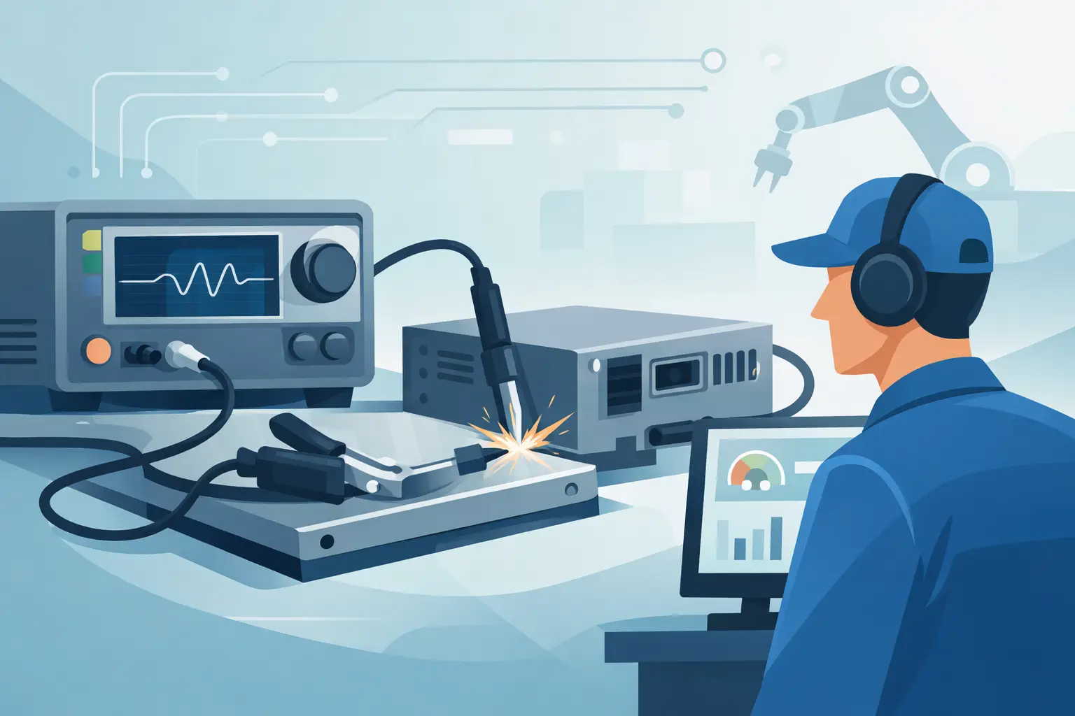
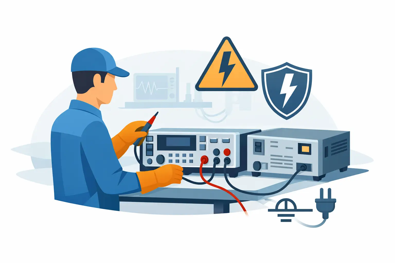
A high-voltage switching fault rarely presents as a simple open or short. A relay may close reliably at low voltage but arc under load. A solid-state device may appear to turn off while leakage current continues to charge a downstream capacitor. A switch matrix may pass a continuity check yet fail its insulation requirement after humidity, contamination, or repeated switching cycles. To troubleshoot high voltage switching effectively, the diagnostic process must separate the command signal, switching device, load behavior, and measurement method.
The goal is not merely to restore operation. In production, qualification, and safety-test environments, the goal is to establish why the fault occurred, verify that corrective action is repeatable, and preserve the measurement integrity needed for compliance records and product decisions.
Start With a Safe, Defined Fault Condition
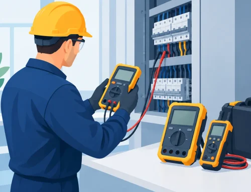
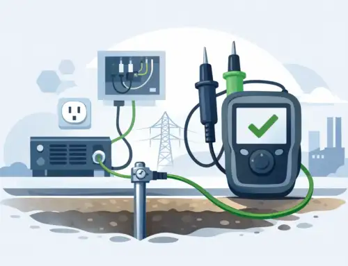
High-voltage troubleshooting begins before a probe touches the circuit. Identify every energy source, including AC mains, DC bus capacitors, battery strings, auxiliary supplies, and externally connected equipment. Follow the facility’s lockout/tagout procedures, discharge stored energy through an appropriate path, and verify the absence of voltage with a properly rated instrument.
The test setup must be evaluated as a complete system. Probe ratings, cable insulation, connector spacing, fixture barriers, interlocks, and the measurement instrument’s input category all need to match the maximum expected voltage and transient environment. A low-voltage oscilloscope probe connected to a floating or fast-switching high-voltage node can create a measurement hazard as well as misleading data.
Before changing components, document the failure condition. Record the commanded state, source voltage, load type, switching rate, ambient conditions, and time since startup. Note whether the problem is repeatable, intermittent, load-dependent, or tied to a particular channel. This baseline prevents a common error: declaring a repair successful after changing the electrical conditions that originally exposed the failure.
Troubleshoot High Voltage Switching by Failure Signature
The fastest path to root cause is usually the observed signature. Classify the behavior first, then select measurements that can distinguish among plausible causes.
The switch will not close
When a mechanical relay or contactor does not close, confirm the control path before condemning the contacts. Measure the coil or driver supply at the device during the close command, not only at the controller output. Voltage drop in long harnesses, weak power supplies, failing driver transistors, incorrect suppression components, and poor ground references can all prevent adequate pull-in energy.
For a solid-state switch, verify the gate-drive or control input amplitude, timing, and reference. An isolated driver may have correct logic at its input but insufficient bias supply at its output. In multiplexed systems, check whether firmware interlocks, channel addressing, or fault latches are intentionally preventing closure.
A coil resistance measurement can identify an open or damaged coil, but it does not prove that the armature moves correctly under operating conditions. Likewise, a static semiconductor junction check cannot confirm correct switching at the actual bus voltage, temperature, and dv/dt.
The switch closes, but the load does not energize
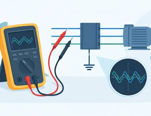
This symptom often points to excessive series resistance, an open load path, or a load that requires a higher inrush current than the switch can deliver. Measure voltage at the source, at both sides of the switching element, and directly across the load during the event. These three locations reveal where voltage is being lost.
A high voltage drop across closed contacts indicates contact resistance, damaged contact plating, incomplete closure, or a current level beyond the device rating. For solid-state switching, the drop may indicate a partially enhanced transistor, insufficient gate drive, thermal damage, or an incorrectly selected device topology.
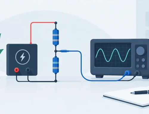
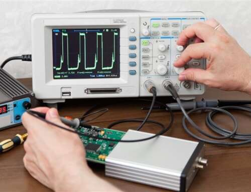
Do not rely on a handheld meter alone for fast events. Inrush current, capacitor charging, and inductive loads can cause a brief collapse that a meter averages away. A properly rated differential probe and a current measurement method with adequate bandwidth are often necessary to capture the actual event.
The switch will not open or leakage remains
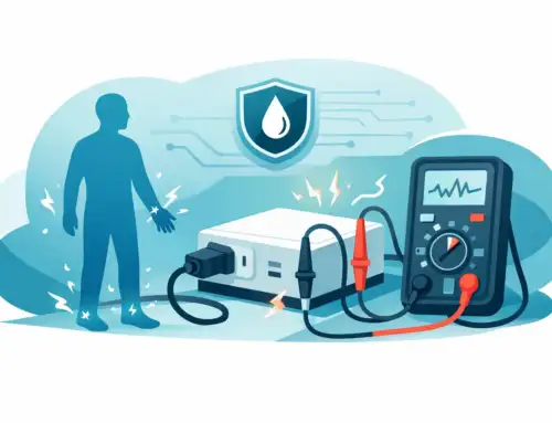
A circuit that remains energized after an open command requires immediate attention. First distinguish between a true welded or shorted switch and a capacitively coupled, stored-charge, or leakage-related voltage indication. Measure available current and discharge behavior using a controlled, rated method. A high-impedance measurement may show substantial voltage on a floating node even when the energy available is limited.
Mechanical contacts can weld after excessive inrush, sustained overcurrent, or repeated arcing. Semiconductor devices can fail short after overvoltage, avalanche stress, thermal overstress, or a gate-drive fault. Contamination across insulators, damaged cable jackets, and moisture on fixtures can also create leakage paths that bypass the intended switch.
Insulation resistance testing can be useful, but it must be performed at a voltage appropriate to the equipment and only after sensitive electronics are isolated. Compare readings across channels and against known-good hardware. A single absolute value is less informative than a controlled comparison under the same temperature, humidity, and test duration.
Arcing, noise, or inconsistent switching
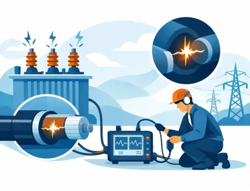
Visible arcing, audible chatter, and intermittent readings frequently originate from the interaction between the switch and its load. Inductive loads generate a voltage transient when current is interrupted. Capacitive loads generate high inrush current when connected. Both conditions can exceed contact or semiconductor limits even when steady-state voltage and current appear acceptable.
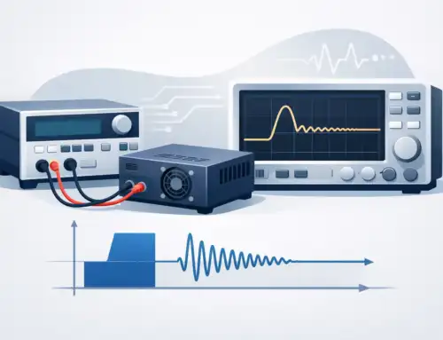
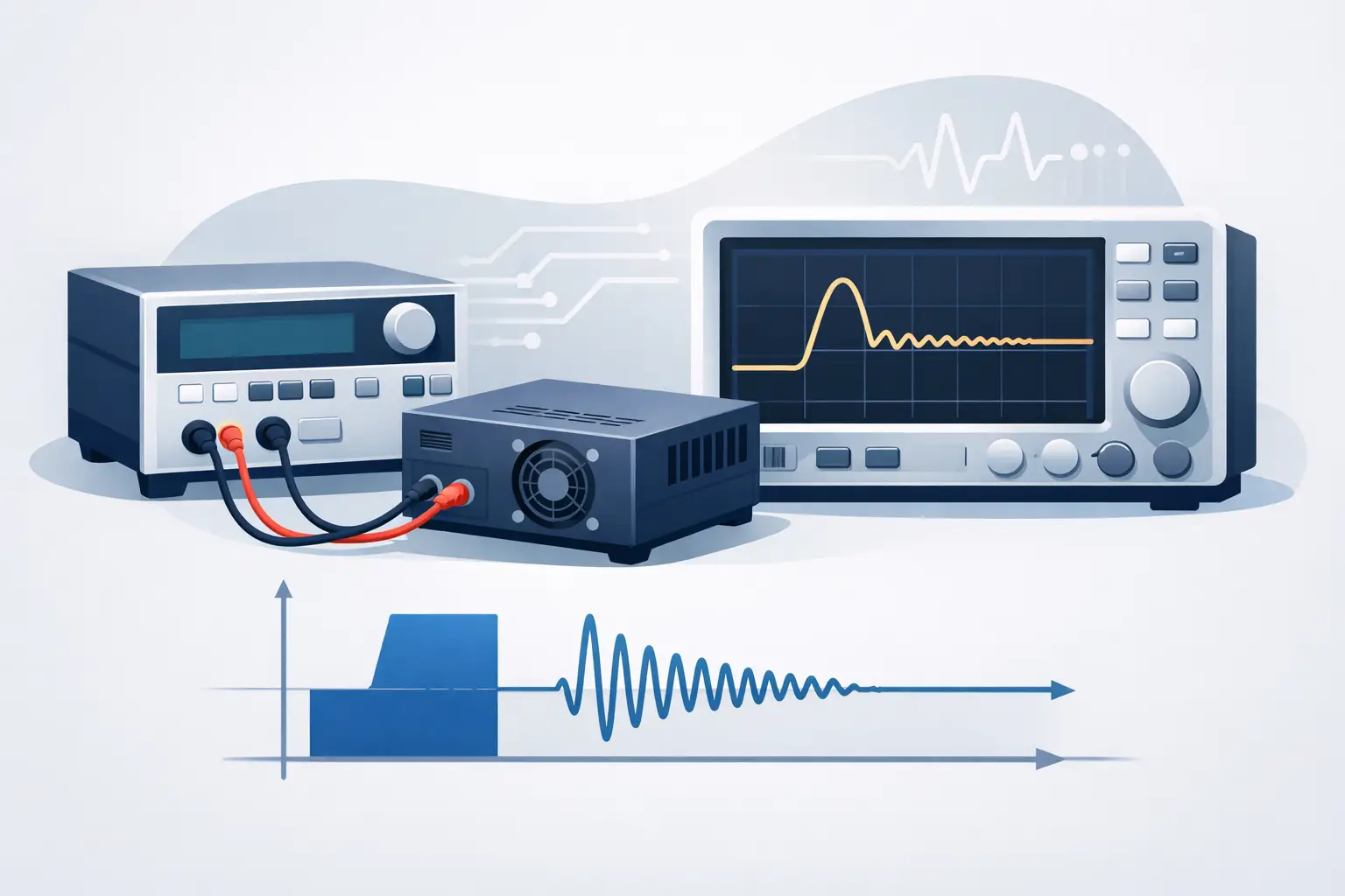
Capture voltage across the switch and current through the load at turn-on and turn-off. Look for excessive overshoot, prolonged ringing, contact bounce, slow gate transitions, or repeated re-ignition. The corrective action may involve a snubber, flyback path, precharge circuit, revised switching sequence, different contact material, or a switch with ratings appropriate to the transient duty.
Suppression is not automatically beneficial. An RC snubber can reduce dv/dt and arcing but may add off-state leakage. A flyback diode can protect a driver but slow the release of an inductive actuator. The correct approach depends on required switching speed, allowable leakage, energy level, and applicable safety requirements.
Verify the Measurement System Before Trusting the Result
High-voltage faults are sometimes measurement artifacts. Ground-referenced instruments can create unintended ground paths. Probe capacitance can alter a high-impedance circuit. A current clamp with limited low-current accuracy may miss leakage that matters to an insulation or hipot application.
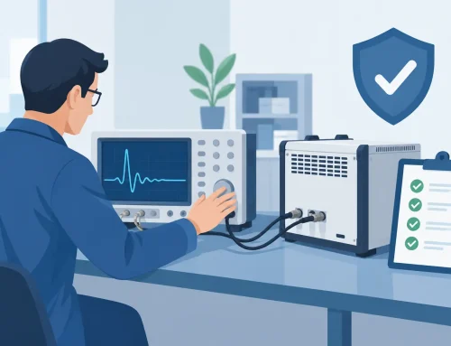
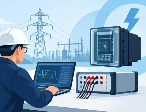
Confirm instrument calibration status and review the voltage, current, bandwidth, common-mode, and crest-factor limits of every measurement component. Use short, controlled probe connections where practical, and keep high-voltage and low-level control wiring physically separated. In automated systems, verify channel mapping, settling time, scan sequence, and the timing relationship between command, measurement, and data logging.
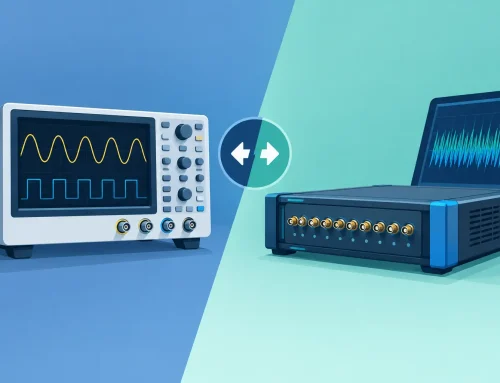
A useful cross-check is to repeat the measurement with a second method. For example, compare a digitized waveform with a calibrated power or current measurement, or compare a suspect channel with a known-good channel under identical load conditions. Agreement between independent methods increases confidence that the observed behavior is real.
Turn Root Cause Into a Repeatable Corrective Action
Replacing a failed relay or switch may restore function, but it does not answer whether the replacement will survive the same duty cycle. Review the application margins: peak voltage, continuous current, inrush, interruption energy, repetitive switching rate, ambient temperature, altitude, contamination level, and expected service life.
For test systems, also examine the fixture and operating procedure. A device under test with an unexpected capacitance or fault condition can impose energy far beyond the nominal test profile. A controlled precharge step, discharge verification, interlocked enclosure, or revised channel sequence may remove the stress mechanism entirely.
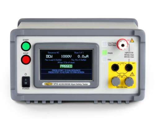
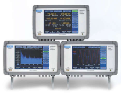
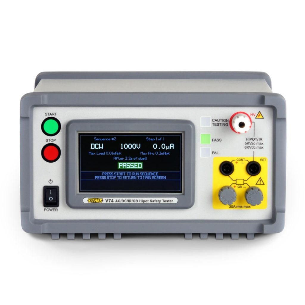
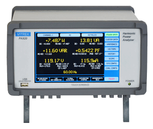
After corrective action, run a defined verification sequence that includes normal operation and the conditions that originally produced the failure. Record waveforms, leakage or insulation results, contact resistance where applicable, and switching timing. High-voltage switching platforms from suppliers such as Vitrek are most valuable when their measurement capability is used to document the full event, not simply the final pass/fail state.
The most useful troubleshooting record connects the failure signature to measured evidence and a specific operating limit. That record gives the next engineer a defensible basis for maintaining safe operation, improving the test process, and recognizing the same fault before it becomes a field or compliance problem.