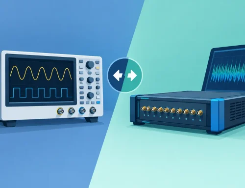
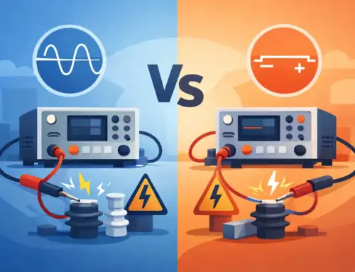
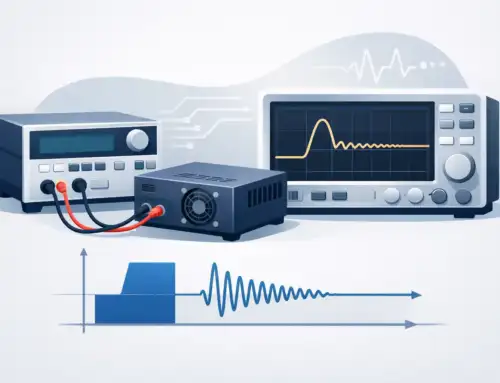
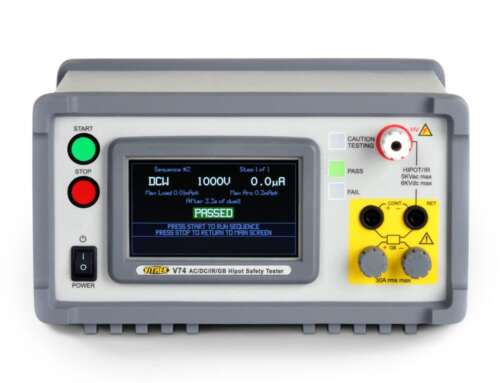
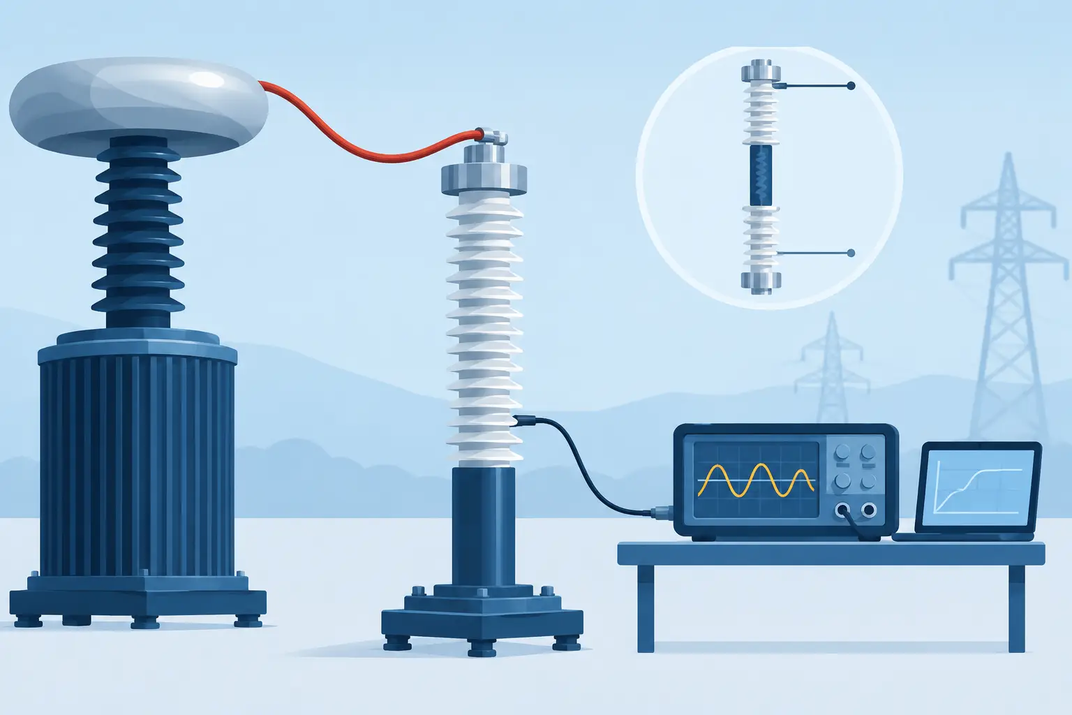
A dielectric withstand test is not simply a matter of applying a high voltage and recording a pass or fail. The choice of AC versus DC hipot changes the electrical stress applied to the device under test, the current the instrument must measure, the test time, and the precautions required after the test ends. For production lines and qualification laboratories, that choice should begin with the applicable standard and the construction of the product, not with the tester already on the bench.
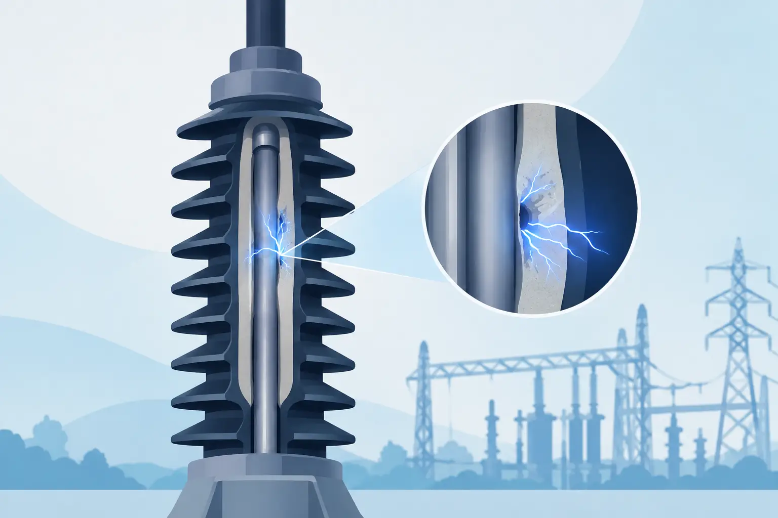
Hipot testing verifies that insulation can withstand a specified overvoltage without breakdown or excessive current flow. It is used on products ranging from power supplies and appliances to medical devices, EV components, cable assemblies, transformers, and aerospace subsystems. A defensible test program accounts for insulation type, accessible conductive parts, stored energy, allowable leakage current, and the governing certification requirement.
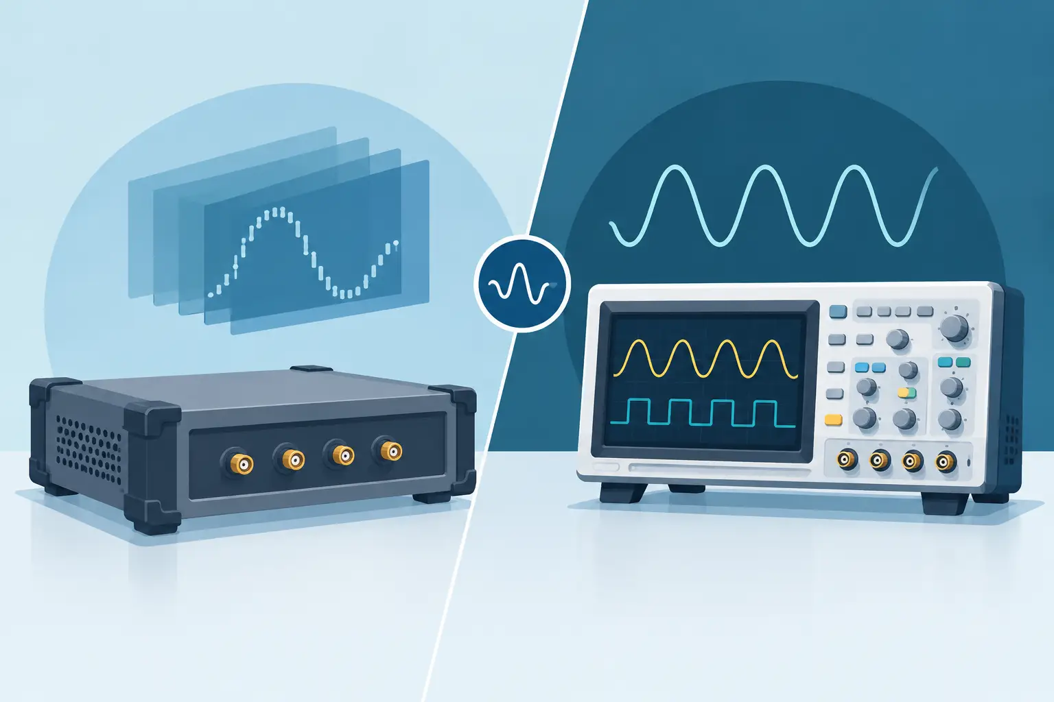
What Changes in AC Versus DC Hipot Testing
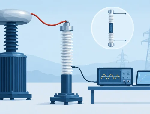
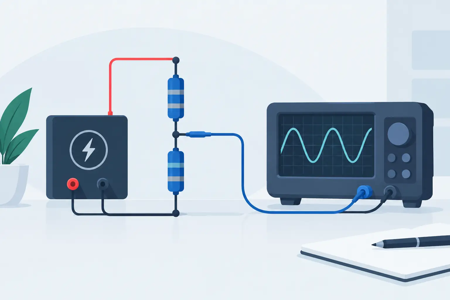
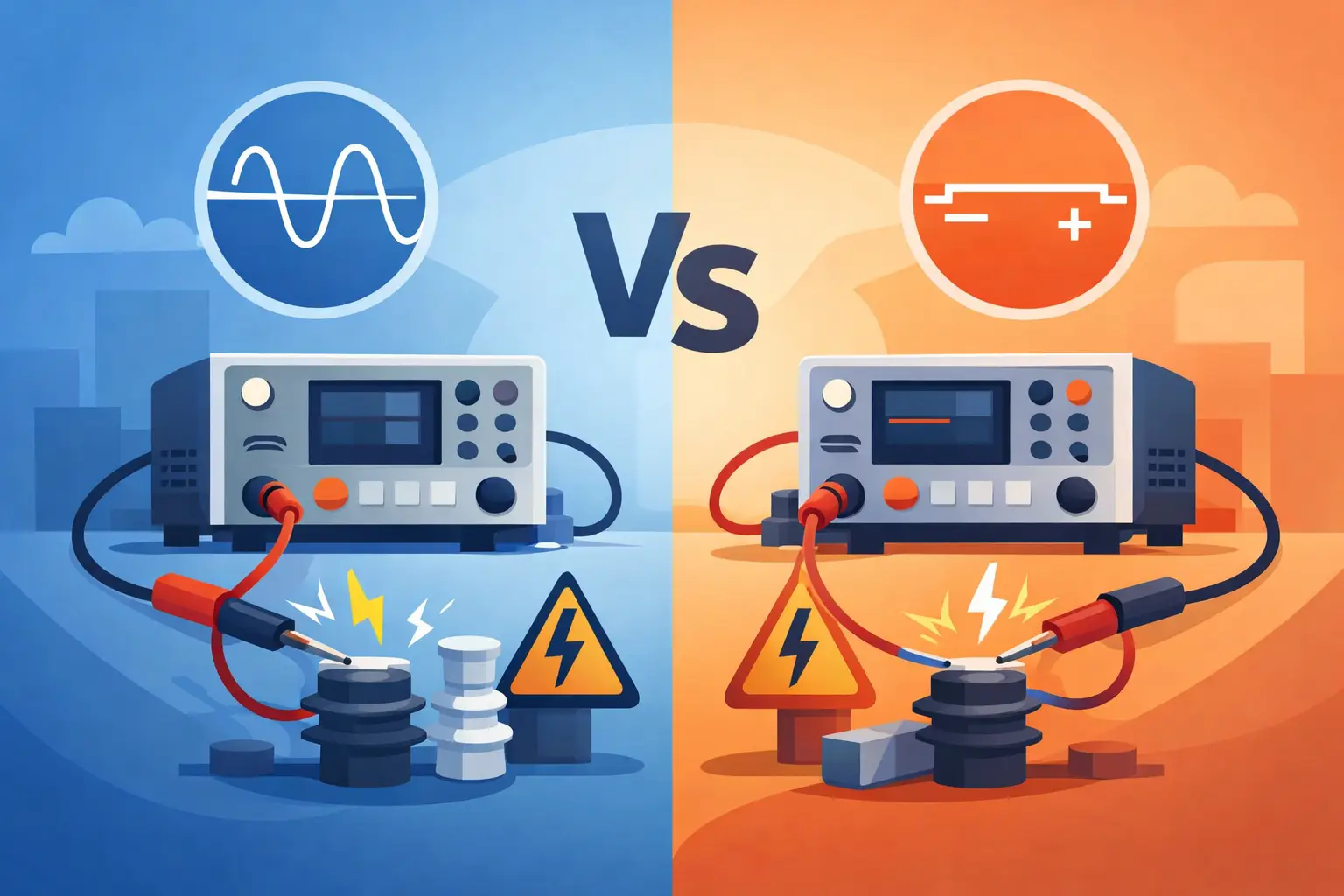
An AC hipot test applies an alternating voltage, typically at line frequency or another specified frequency, between the required test points. The alternating field repeatedly reverses polarity. This produces current through both the resistive portion of the insulation and its capacitance.
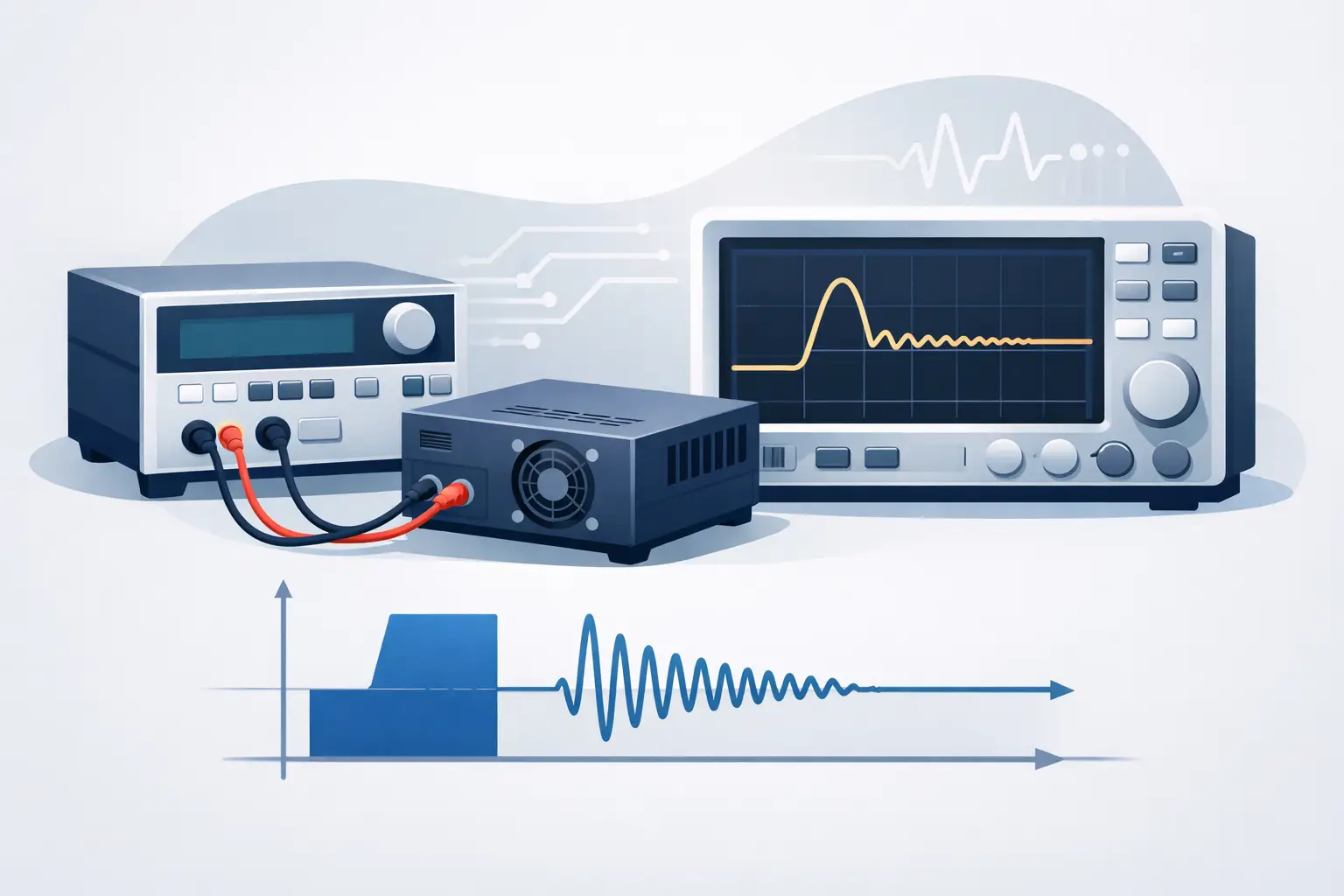
A DC hipot test applies a unidirectional voltage. After an initial charging transient, the measured current is primarily related to insulation resistance, dielectric absorption, and surface leakage. The capacitive charging current decays as the test object reaches the applied voltage.
That difference is central to test interpretation. A highly capacitive product can draw substantial current during an AC test even when its insulation is sound. In a DC test, the same product may show a high current during ramp-up followed by a much lower steady-state value. Neither result is inherently better. Each reflects a different electrical condition, and each must be evaluated against an appropriate limit and procedure.
AC testing is commonly selected when a standard explicitly requires AC withstand voltage or when the manufacturer needs to evaluate insulation under alternating stress representative of the equipment’s operating environment. DC testing can be advantageous for capacitive assemblies, high-volume applications where controlled ramp and discharge are needed, and products whose governing requirements permit a DC equivalent.
Voltage Equivalence Requires Care
A frequent source of error is treating AC and DC test voltages as interchangeable. They are not. For a sinusoidal waveform, the peak voltage is approximately 1.414 times the RMS voltage. As a result, a DC test voltage is often specified at approximately 1.414 times an AC RMS test voltage when the objective is to provide comparable peak electrical stress.
However, this relationship is not a universal substitution rule. Product standards, certification bodies, and internal validation plans may prescribe a specific test type, voltage, dwell time, ramp profile, and leakage limit. Some standards provide their own DC conversion factors. Others require AC testing without a DC alternative. The test specification always takes precedence over a general conversion convention.
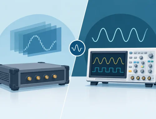
Test engineers should also distinguish between the programmed voltage and the voltage actually delivered to the DUT. Lead resistance, fixture design, switching arrangements, and instrument regulation can affect the applied condition, particularly in automated systems. A calibrated tester with appropriate measurement capability, controlled ramping, and traceable records reduces uncertainty in both production and engineering investigations.
AC Hipot: Strengths and Limitations
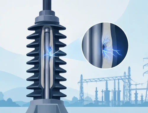
AC hipot testing subjects insulation to continuous polarity reversal. Because the capacitive component of current remains present throughout the dwell period, AC testing can impose more demanding current requirements on the source and measurement system. This is particularly relevant for long cables, EMI filters, motors, transformers, and assemblies with large distributed capacitance.
The principal strength of AC testing is that it directly satisfies standards that call for an AC dielectric withstand test. It also avoids retaining a DC charge in the DUT after the test, although safe test practices and verification remain necessary. For products intended to operate on AC mains, the waveform may also provide a meaningful representation of operating-field reversal at an elevated voltage.
The limitation is that total measured current includes reactive current. A leakage limit that is appropriate for a small resistive load may be impractical for a capacitive product. Test limits therefore need to account for expected capacitive current, instrument capability, and the specific current measurement method. Raising the current limit merely to prevent nuisance failures is not a sound approach unless the resulting limit remains consistent with the product standard and the failure mechanisms the test is meant to detect.
AC tests can also require higher apparent power from the test system. Before defining a production test, calculate the anticipated capacitive current at the selected voltage and frequency. This helps prevent voltage regulation problems, false trips, and undersized test infrastructure.
DC Hipot: Strengths and Limitations
DC hipot testing is often easier to apply to highly capacitive DUTs because the charging current is transient rather than continuous. Once the capacitance is charged, the current can settle to a lower value that is more closely associated with resistive leakage and dielectric absorption. This can improve discrimination between normal capacitive behavior and abnormal insulation leakage.
DC testing also enables deliberate control of ramp rates and dwell periods. A controlled ramp can limit inrush current, reduce unnecessary electrical shock to sensitive assemblies, and produce more repeatable readings. The time profile matters. Measuring current immediately after reaching the test voltage may characterize charging behavior rather than insulation condition. Measuring after a defined stabilization interval provides a more meaningful basis for comparison.
Its primary trade-off is stored energy. A capacitance charged to high DC voltage can remain energized after the test source turns off. The test system must safely discharge the DUT, and the procedure must verify that discharge is complete before operators can access the fixture. This is not optional on high-capacitance products. Discharge circuitry, interlocks, guarded fixtures, warning indicators, and documented safe-work procedures are fundamental parts of the test system.
DC may also be less sensitive to certain defects that respond differently under continuously reversing electrical stress. That does not make DC testing inadequate when it is permitted by the governing requirement. It means the method must be selected for the intended failure mode and compliance objective.
Selecting the Right Hipot Method
The most reliable selection process begins with the required standard. If a certification, customer, or regulatory document mandates AC or DC, the decision is already made. Engineering judgment then focuses on implementing the method correctly.
When both approaches are permitted, evaluate the DUT as an electrical system. Its capacitance, insulation geometry, operating voltage, intended environment, and failure history all matter. A low-capacitance appliance assembly may be well suited to AC testing. A large filter network, cable harness, or motor winding may favor DC testing if the standard allows it, because the steady-state leakage measurement can be easier to control and interpret.
Consider these practical questions before releasing the procedure:
- Does the governing standard specify the waveform, voltage, dwell duration, ramp rate, or maximum allowable current?
- What capacitive current will the DUT draw at the required AC voltage and frequency?
- If using DC, how long does the DUT require to charge, stabilize, and safely discharge?
- Can the tester distinguish a true dielectric failure from fixture leakage, surface contamination, or normal capacitive behavior?
- Are the fixture, safety interlocks, measurement ranges, and data records adequate for the production environment?
These questions should be addressed during method development, not after a line begins generating unexplained failures. A representative sample study can establish normal current behavior, identify fixture effects, and support rational test limits. For critical products, correlation with insulation resistance measurements, functional testing, and environmental stress data may provide a more complete assessment than hipot results alone.
Measurement Integrity and Safety Controls
A dielectric withstand result is only as credible as the test setup. Fixture leakage can obscure DUT leakage, especially at high voltage or in humid environments. Cleanliness, conductor spacing, guarded connections, shielded cabling where appropriate, and periodic fixture verification are practical controls that protect measurement integrity.
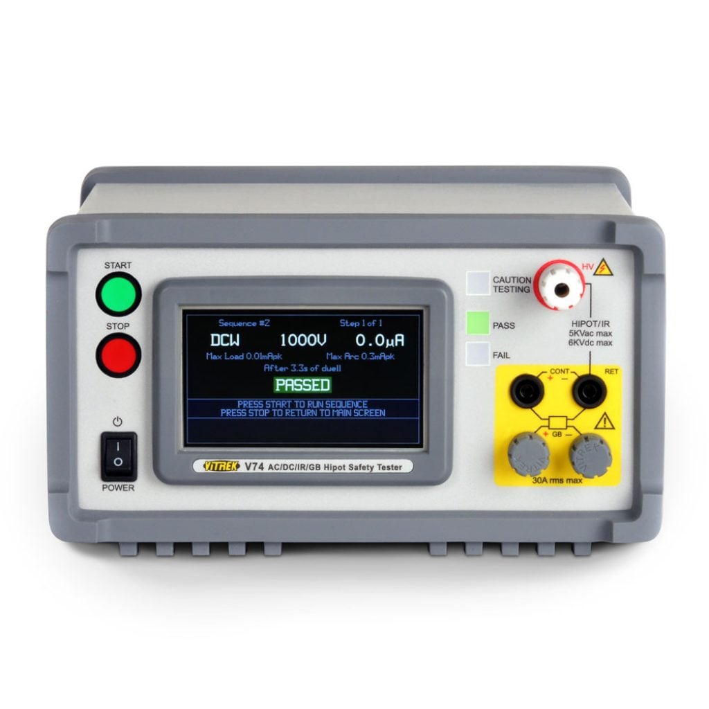
The tester should provide voltage regulation, current measurement resolution appropriate to the limit, programmable timing, and clear failure indication. Automated stations benefit from controlled sequencing and recorded test parameters, including the actual voltage, measured current, dwell time, pass/fail outcome, and test configuration. Those records support traceability, process troubleshooting, and audits.
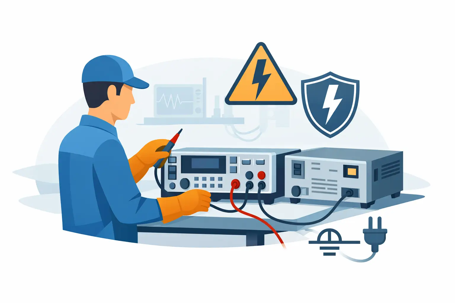
Operator protection deserves equal attention. High-voltage testing requires guarded enclosures or protected fixtures, interlocks that inhibit output when access is available, emergency-stop provisions, warning indicators, and a defined response to faults. For DC systems, the discharge path must be sized for the DUT’s stored energy and verified as part of the station’s operating sequence. A passing electrical result does not offset an unsafe test process.
Build the Procedure Around the Requirement
The practical distinction between AC and DC hipot testing is not that one method is universally more severe or more modern. AC applies continuous alternating stress and includes ongoing capacitive current. DC separates charging behavior from steady-state leakage but introduces stored-energy management and may not satisfy every standard.
For a reliable decision, start with the compliance requirement, model the DUT’s capacitance and expected leakage, then validate the selected method with a controlled fixture and calibrated instrumentation. That approach gives engineering teams more than a pass/fail signal: it produces repeatable evidence that the insulation system and the test process can be trusted.