A rotating assembly can meet dimensional tolerances, pass a functional run test, and still create a costly vibration problem. The difference is often residual unbalance that was not measured at the speed, sensitivity, or correction plane required by the application. The best engine balancing systems give engineering and production teams a defensible path from vibration data to a verified correction – with repeatable results that can be documented, reviewed, and acted on.
For engine manufacturers, rebuild operations, aerospace programs, and high-performance powertrain developers, balancing is not simply a finishing operation. It affects bearing life, noise and vibration performance, structural fatigue, test-cell reliability, and customer acceptance. Selecting a system therefore requires more than comparing maximum part weight or advertised balancing speed.
What Defines the Best Engine Balancing Systems?
An engine balancing system should be evaluated as a measurement and correction platform, not as a standalone machine. The system must accurately identify the magnitude and angular location of unbalance, distinguish real rotor behavior from measurement noise, and support a correction process appropriate to the component and its service environment.
The first question is whether the assembly is treated as a rigid rotor or a flexible rotor. A crankshaft, flywheel, clutch assembly, armature, turbocharger rotor, or driveshaft may appear similar from a production perspective, but their balancing requirements can be substantially different.
Rigid rotors operate below their first critical speed, so unbalance can generally be corrected in one or two planes. Most engine components handled on production balancing equipment fall into this category. Flexible rotors operate through one or more critical speeds, which introduces mode shapes and requires high-speed balancing methods, often with multiple measurement planes. Applying a rigid-rotor method to a flexible rotor can produce acceptable readings at one speed while leaving damaging vibration at another.
The best choice depends on the rotor type, operating speed range, production volume, residual unbalance specification, and the required evidence of conformance. A system intended for occasional repair work has different priorities than one supporting automated, traceable production of safety-critical assemblies.
Start With the Assembly and Its Balance Quality Requirement
Balance quality is commonly expressed using ISO balance quality grades, where the permissible residual unbalance is related to rotor mass and service speed. The practical implication is direct: as speed increases, allowable residual unbalance decreases. A rotor that is satisfactory for a low-speed industrial engine may be unacceptable for an automotive, aerospace, or high-speed electrified powertrain application.
Before specifying equipment, define the heaviest and lightest expected assemblies, their outside diameters, bearing journal geometry, correction planes, and maximum operating speed. Also document the tolerance in engineering units rather than relying only on a pass/fail label. Teams should know whether their requirement is expressed as unbalance mass, eccentricity, unbalance moment, or a grade-based limit.
A balancing system must resolve unbalance well below the acceptance limit. If its measurement resolution is too close to the allowed residual value, normal process variation, fixture effects, and sensor noise can obscure the actual condition of the part. This is especially significant when balancing small, high-speed rotors where the correction mass may be minimal but the effect at speed is substantial.
One-Plane, Two-Plane, and Assembly Balancing
One-plane balancing is suitable when the rotor is narrow relative to its diameter or when couple unbalance is not significant. Two-plane balancing is typically required for crankshafts, flywheels, and longer rotating assemblies because it identifies both static and couple unbalance.
Assembly balancing deserves separate consideration. Individual components can be balanced within tolerance yet generate unacceptable vibration once fasteners, pulleys, clutches, dampers, or mating parts are installed. If the product is shipped and operated as an assembly, the final balance process should reflect the actual configuration, including representative hardware and torque conditions.
This requirement often drives fixture design. A fixture that does not locate the component consistently, introduces runout, or changes clamping forces between cycles can become the dominant source of variation. High-quality balancing hardware cannot compensate for an unstable mechanical interface.
Measurement Fidelity Matters More Than Display Resolution
A controller can display many decimal places without delivering meaningful accuracy. Measurement fidelity depends on the entire signal chain: vibration sensors, phase reference, mechanical supports, spindle or drive behavior, data acquisition, filtering, and the algorithms used to calculate correction values.
Look for systems that maintain stable phase measurement and repeatable amplitude readings across the operating range. Phase accuracy is essential because a small angular error can turn a correct mass calculation into an incorrect physical correction. This is particularly relevant for automated drilling, milling, or weight-addition stations where the system must precisely direct a downstream process.
Repeatability studies should be part of acceptance planning. Run the same qualified rotor through multiple cycles, remove and reinstall it, and evaluate the spread in indicated unbalance and correction angle. This reveals the combined effect of machine mechanics, fixturing, sensor performance, and operator handling far better than a single demonstration run.
Production teams should also ask how the system manages interference from adjacent equipment, floor vibration, belt or drive disturbances, and changing rotor surface conditions. A controlled laboratory result has limited value if the machine cannot maintain measurement integrity on the plant floor.
Select a Correction Method That Fits the Process
The balancing measurement is only half of the operation. The correction method determines cycle time, repeatability, rework risk, and safety controls. Common approaches include material removal by drilling or milling, mass addition through welding or fasteners, and selective assembly using indexed components.
Material removal is common for crankshafts and flywheels because it can be automated and provides a permanent correction. It also requires clear limits on allowable removal depth, location, and remaining wall thickness. Those limits should be embedded in the process plan, not left to operator judgment.
Mass addition can be effective where material removal would compromise strength or surface finish. However, the added material must remain secure through temperature cycling, corrosion exposure, and operational loading. For rotating assemblies used in regulated or mission-critical environments, the correction method must be reviewed as part of the component qualification.
The best engine balancing systems support the selected correction process with clear operator guidance, angular indexing, tolerance checks, and confirmation runs. A correction instruction without verification is not a closed-loop process.
Software and Data Traceability Are Production Requirements
Balancing software should make the process easier to control, not merely easier to operate. At minimum, it should present unbalance magnitude, correction angle, plane-specific results, tolerance limits, and final residual values in an unambiguous format. For complex applications, recipe control is equally important. Each rotor family may require distinct setup parameters, measurement speeds, correction planes, tolerance bands, and reporting fields.
Traceability becomes essential when the balancing result is part of a quality record. A useful system can associate results with serial numbers, work orders, operators, fixtures, date and time, and process recipes. It should also preserve both the initial condition and final verified result. This allows quality teams to investigate drift, compare production lots, and demonstrate conformance during customer or regulatory audits.
Integration requirements vary. A manual cell may only need exportable reports, while a high-volume line may need communication with a manufacturing execution system, automated correction equipment, barcode readers, or plant-level data collection. Define those interfaces early. Retrofitting connectivity after installation often creates unnecessary validation work and process downtime.
Mechanical Design, Safety, and Serviceability
A balancing machine is a rotating test system, so guarding and containment must match the stored energy of the workpiece and its intended speed. Consider interlocked guards, overspeed protection, emergency-stop architecture, safe loading procedures, and containment for credible component failures. These are engineering requirements, not accessories.
Mechanical capacity also includes support design, drive method, tooling changeover, and the ability to accommodate realistic production variation. A machine that meets nominal part dimensions but requires excessive adjustment for each variant may undermine throughput and increase setup errors.
Serviceability should carry real weight in procurement. Calibration procedures, sensor replacement, spare-part availability, software support, operator training, and application assistance influence the total cost of ownership. For facilities with formal quality systems, calibration traceability and documented maintenance practices are often as important as the initial machine specification.
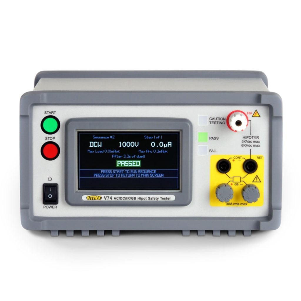
Vitrek’s instrumentation perspective is relevant here: balancing performance depends on trustworthy measurement, not just mechanical motion. The selected platform should provide the diagnostic visibility needed to identify whether a problem originates in the rotor, the fixture, the drive, or the measurement chain.
A Practical Evaluation Approach
The strongest procurement decision is usually based on representative parts rather than generic specifications. Supply candidate vendors with drawings, balance limits, anticipated correction methods, production targets, and sample rotors if possible. Ask for a demonstration that includes initial measurement, correction guidance, final verification, and repeatability across multiple load cycles.
Evaluate the result against the conditions that matter in your facility: operator changeover, expected throughput, reporting needs, available utilities, safety requirements, and maintenance resources. A system with the highest theoretical sensitivity may not be the best fit if its tooling or correction method cannot sustain the required cycle time. Conversely, a low-cost machine may create expensive downstream failures if it cannot demonstrate stable, traceable residual unbalance results.
The right balancing system gives engineers confidence in the rotating assembly before vibration becomes a field failure, a test-cell interruption, or a quality escape. Treat the selection as an investment in measurement discipline, fixture integrity, and verified correction – because those are the controls that keep balance specifications meaningful after the part leaves the machine.