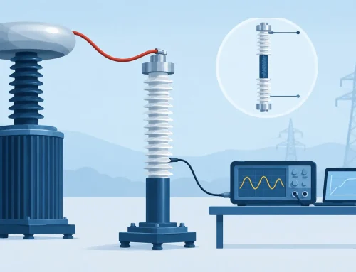
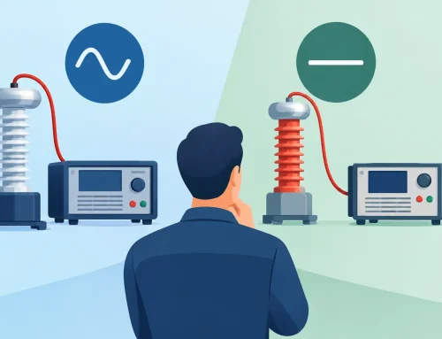
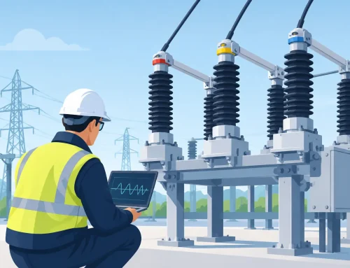
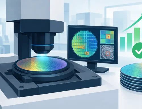
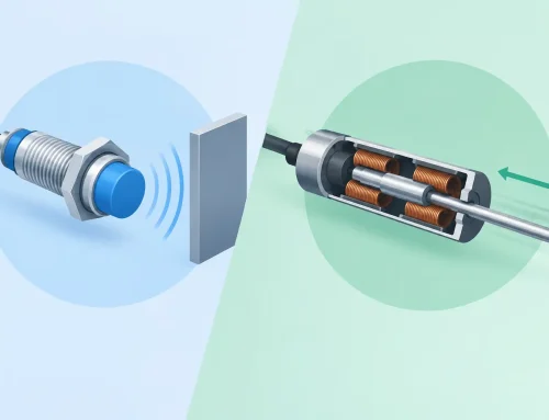
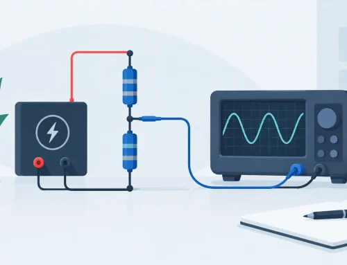
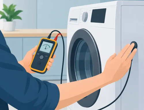
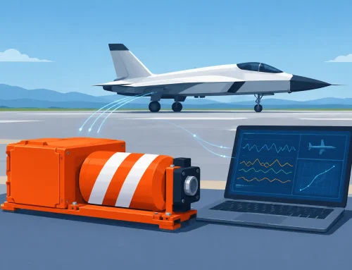
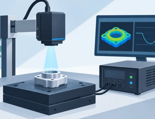
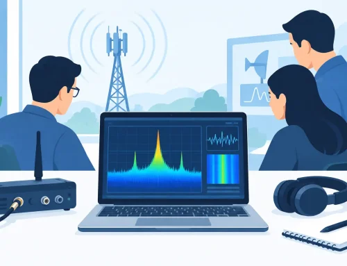
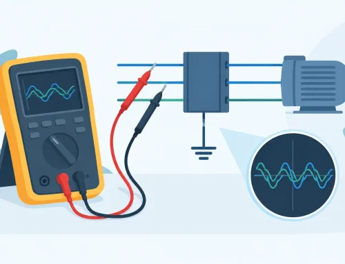
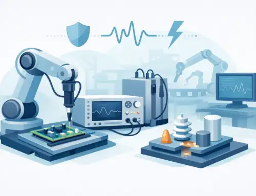
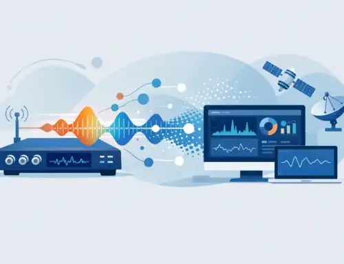
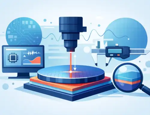
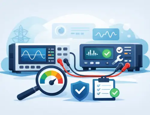
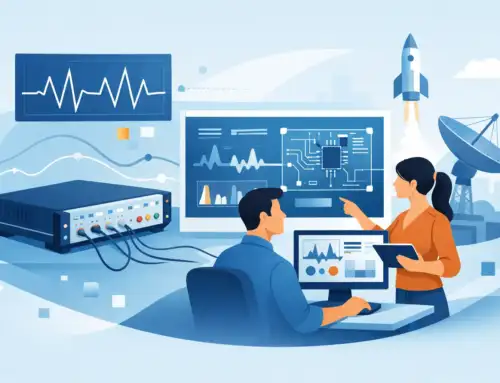
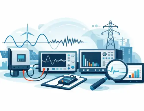
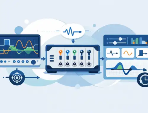
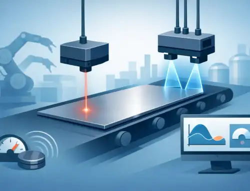
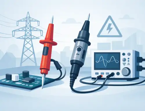
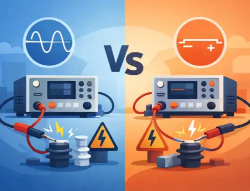
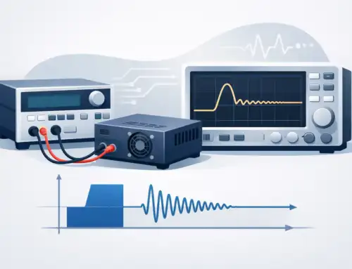
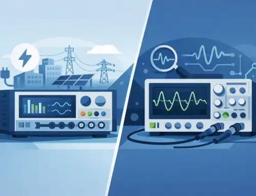
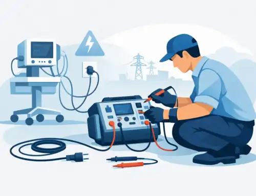
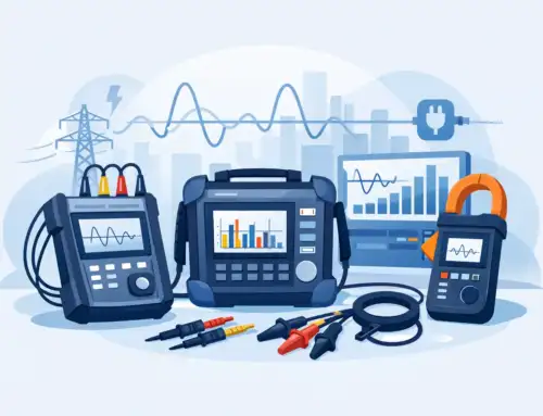
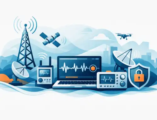
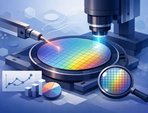
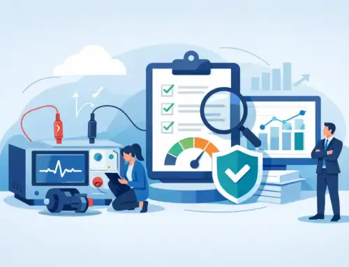
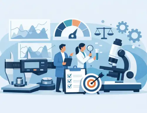
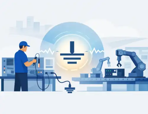
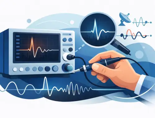
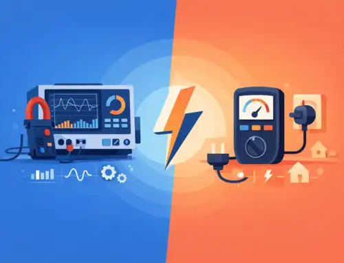
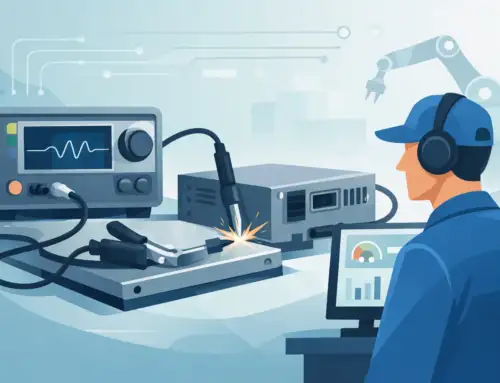
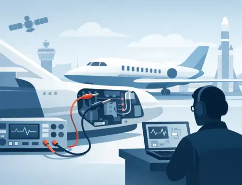
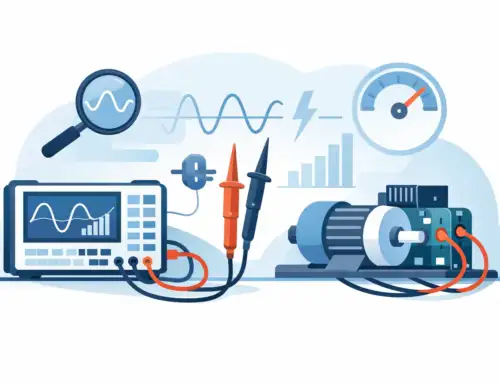
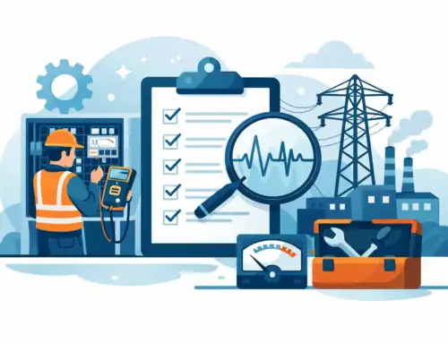
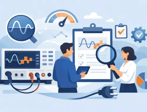
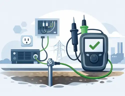
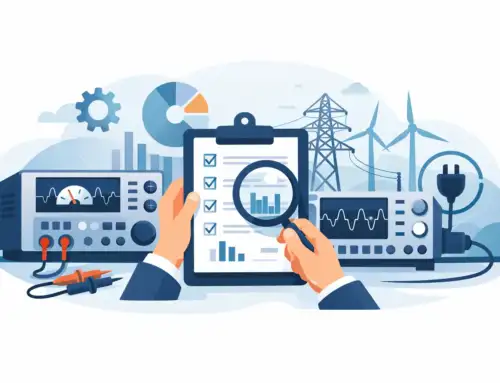
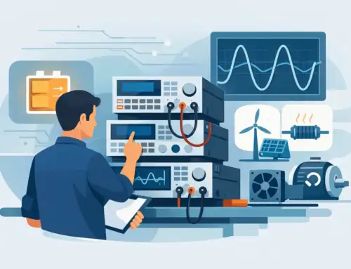
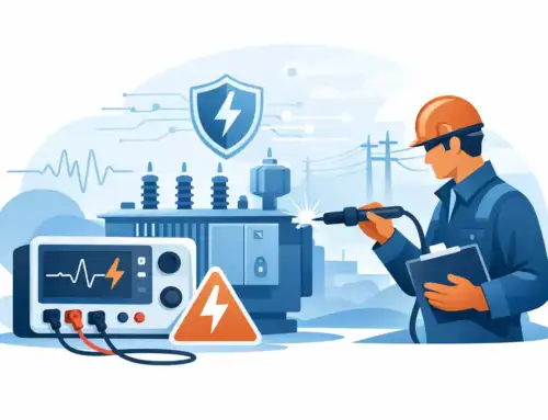
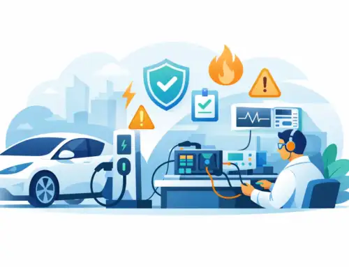
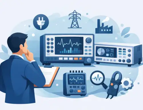
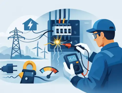
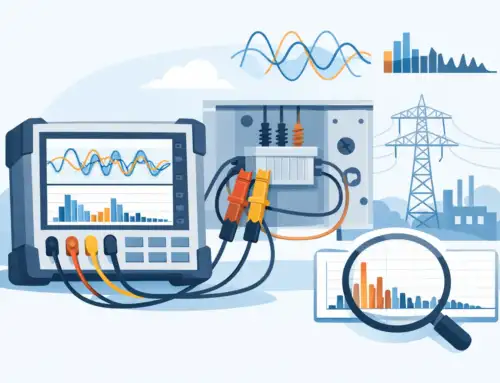
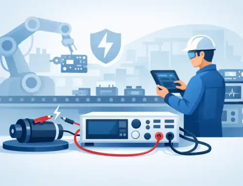
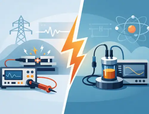
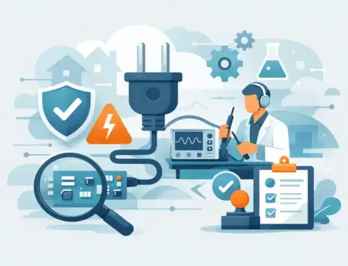
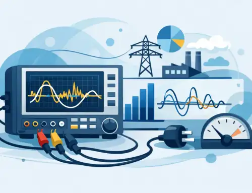
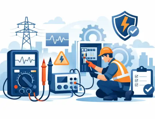
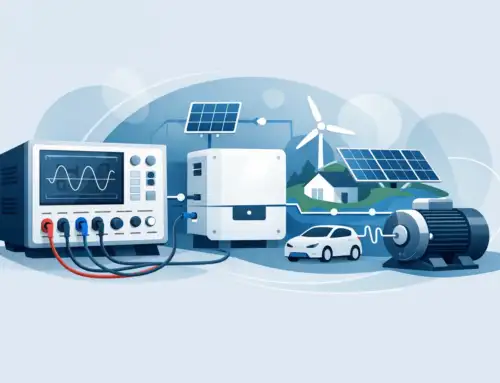
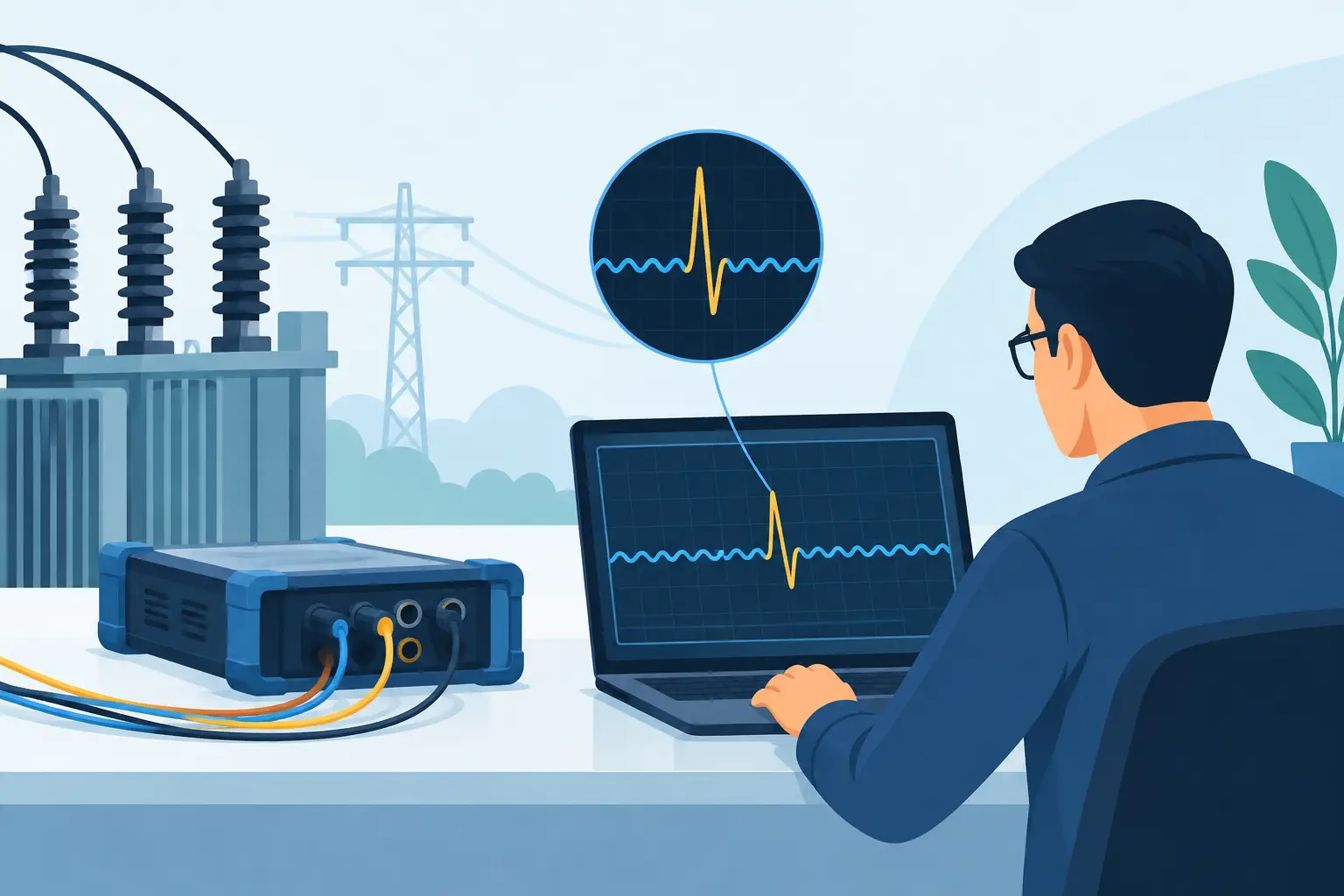
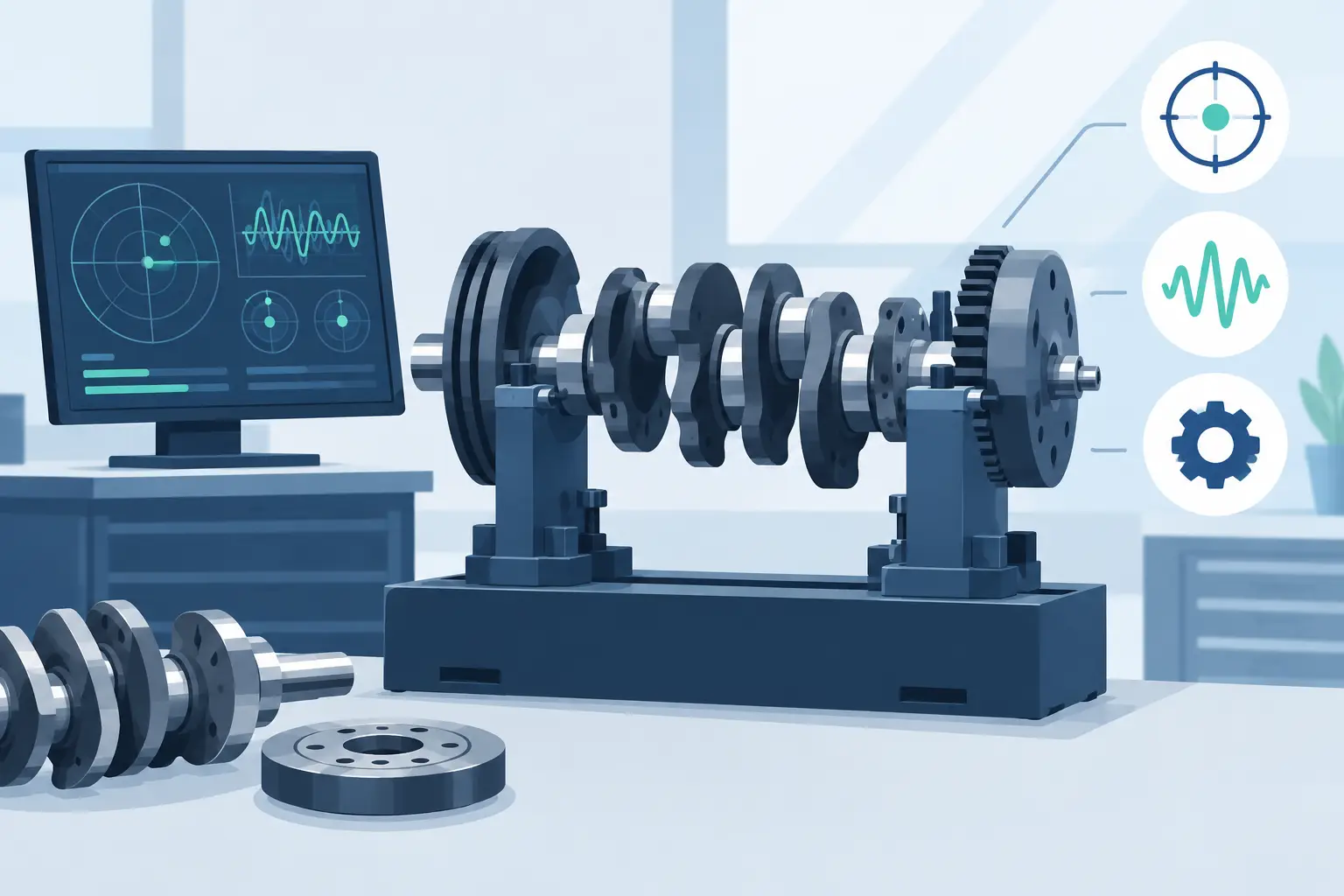
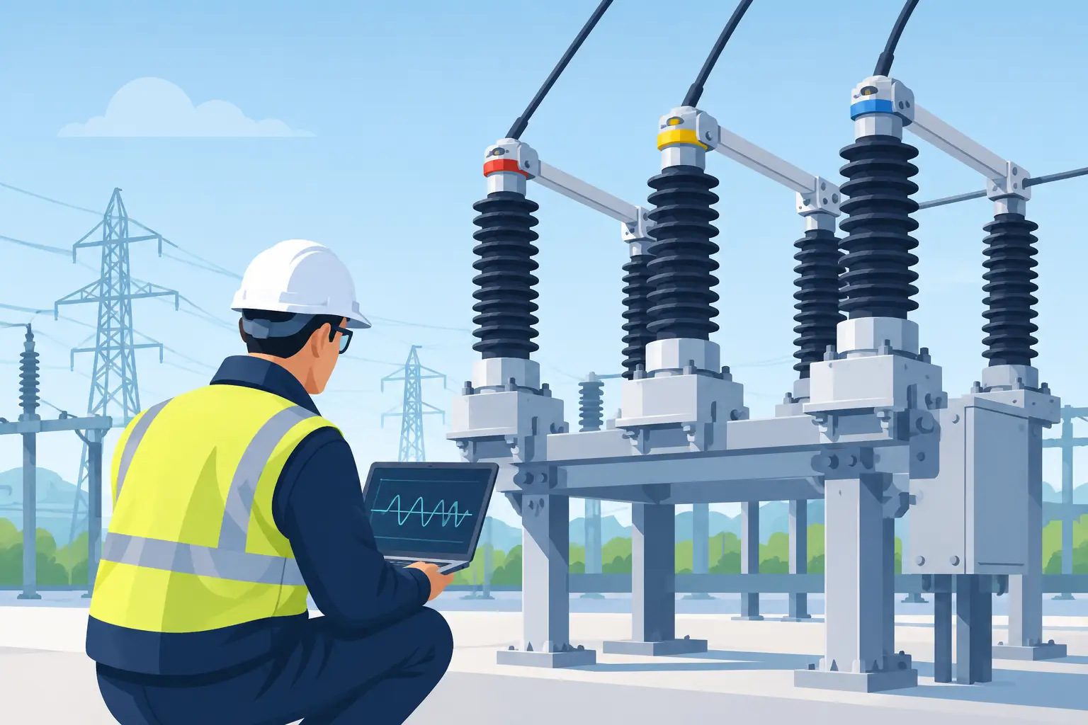
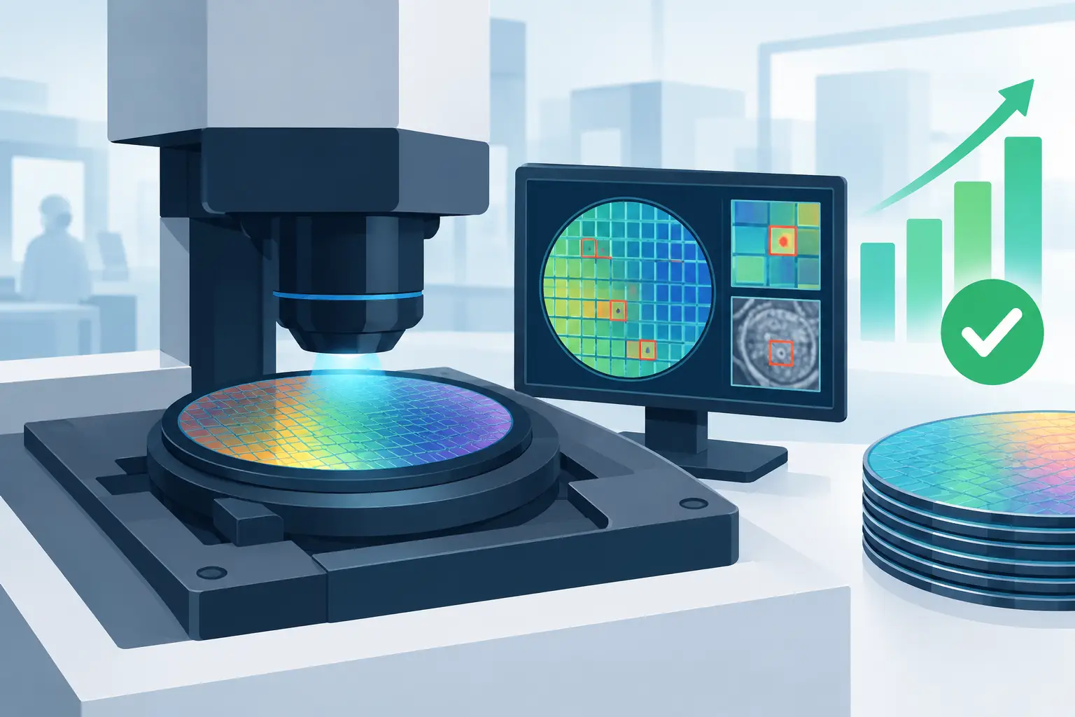
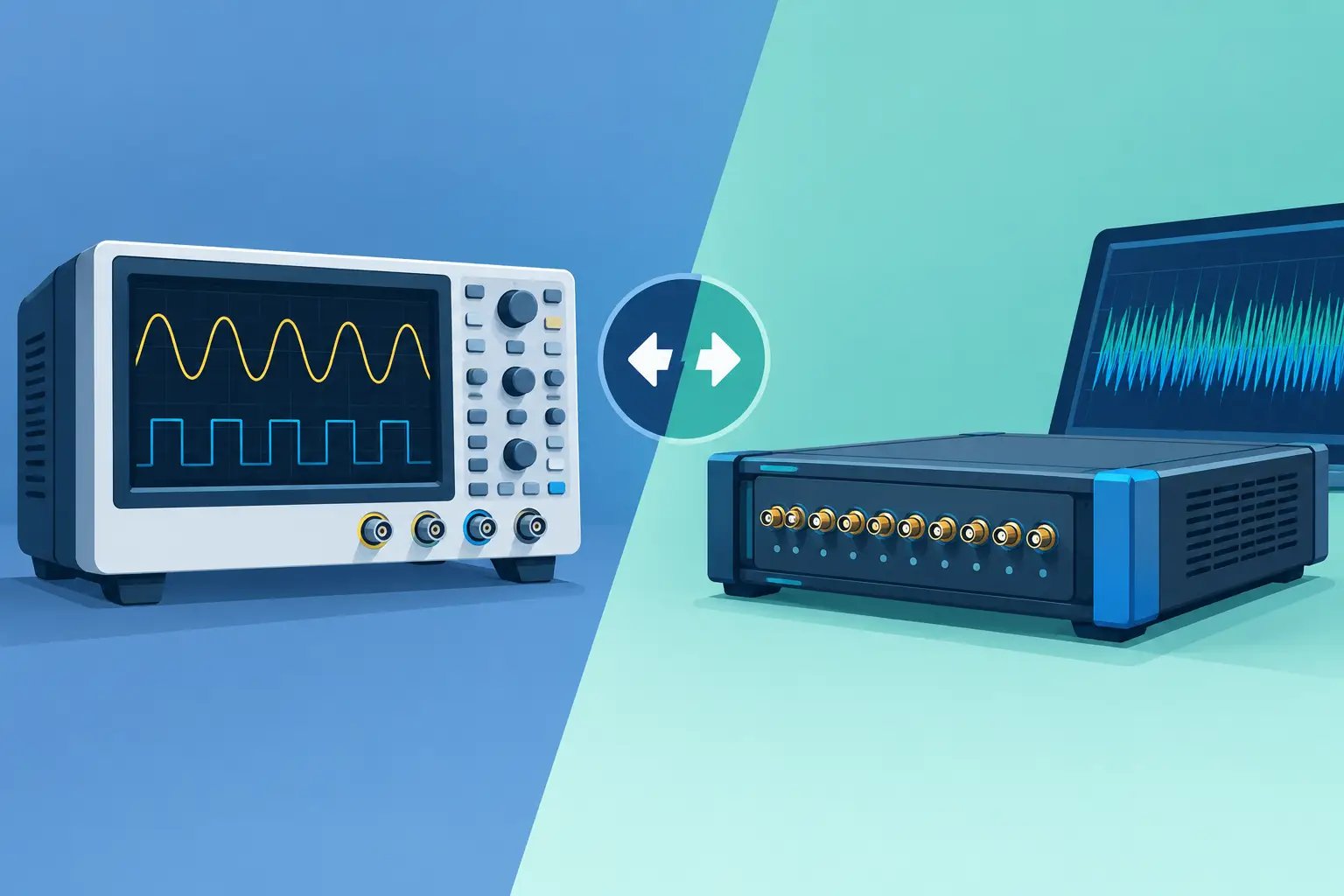
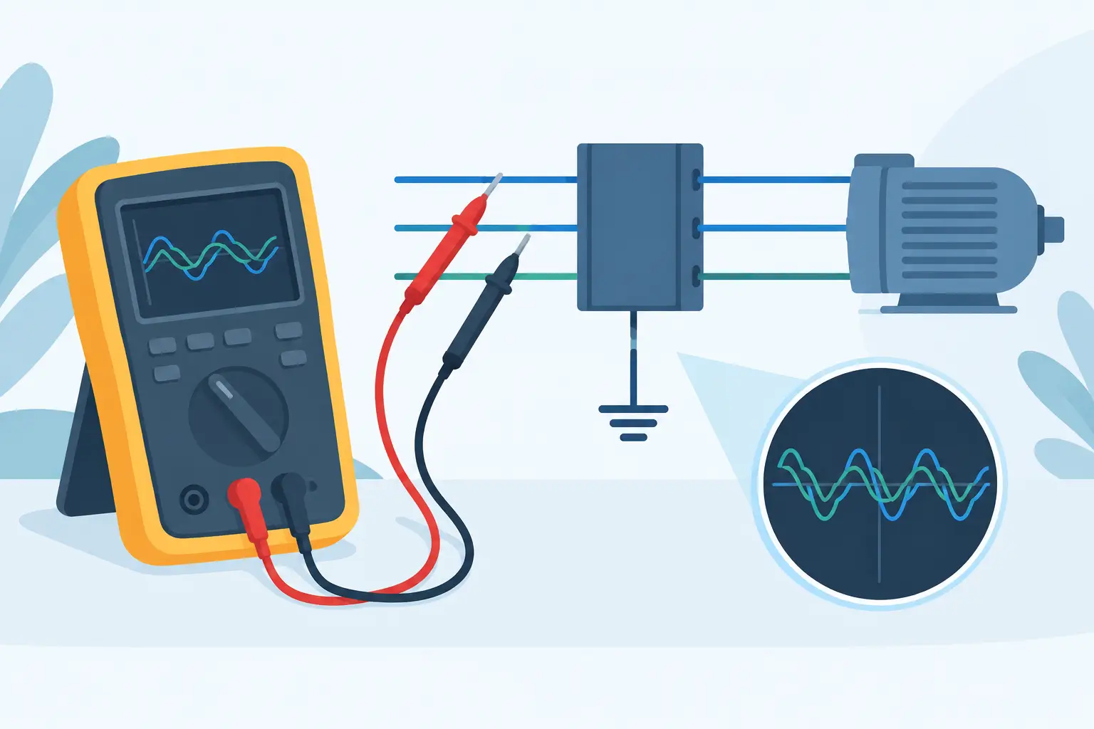
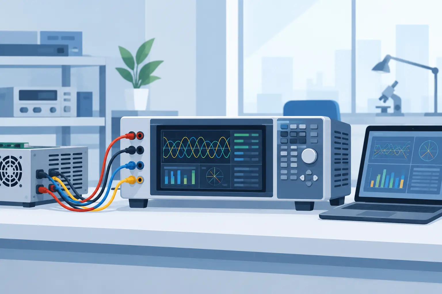
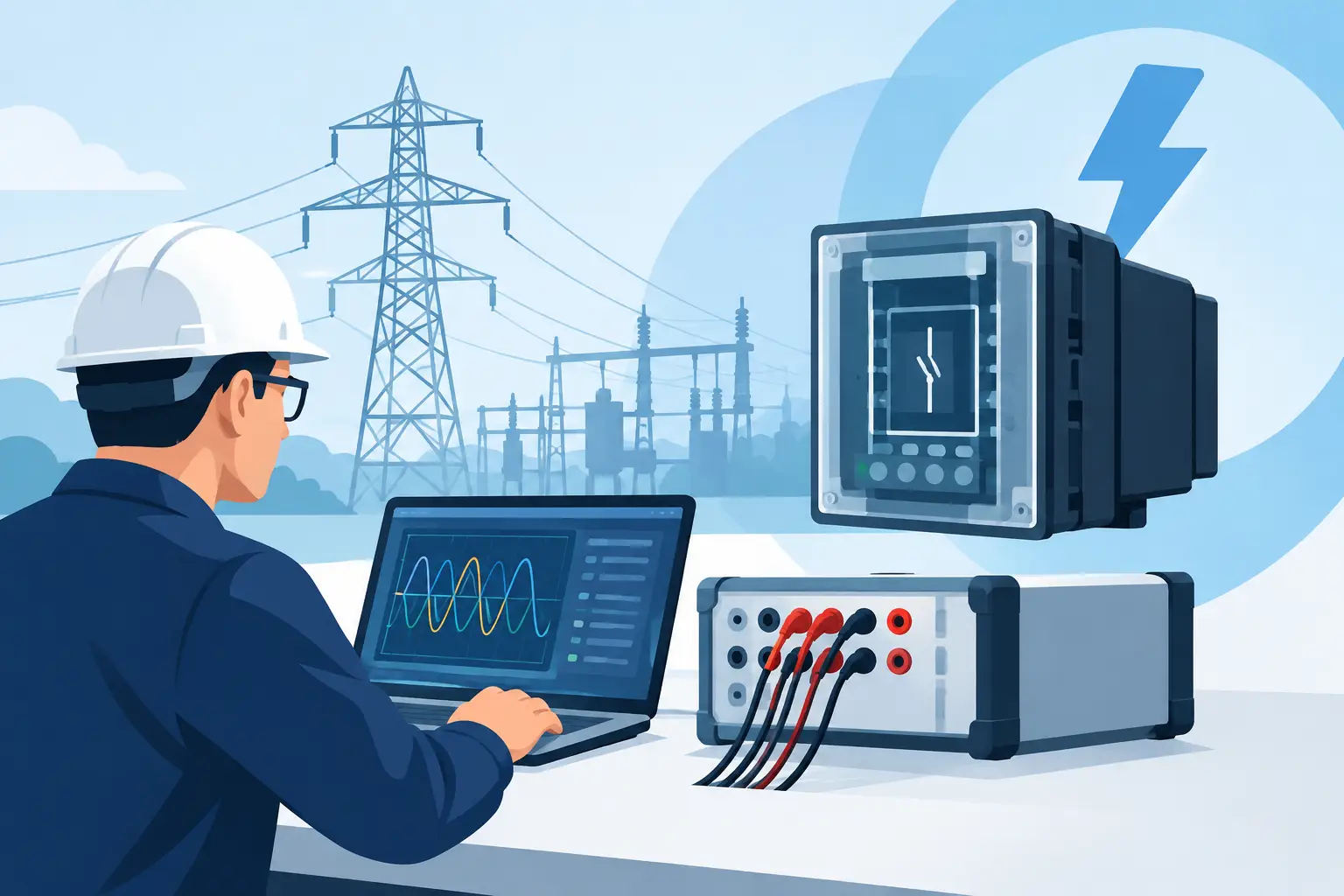
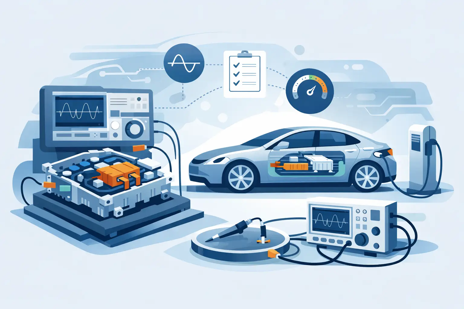
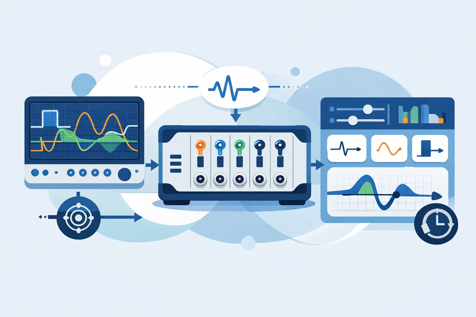
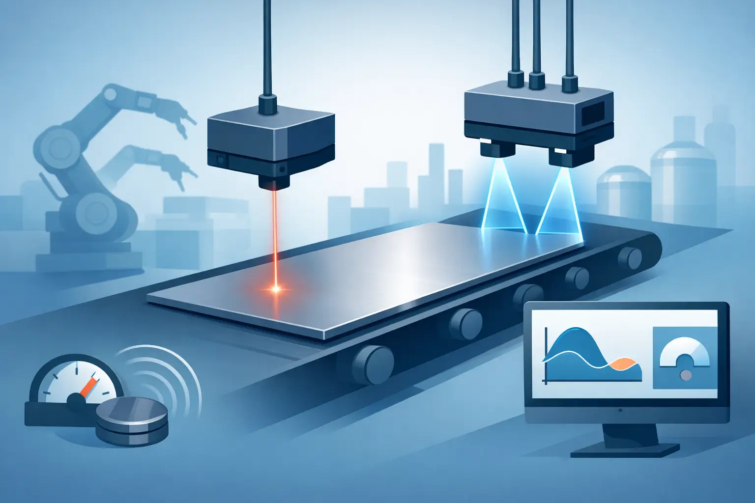
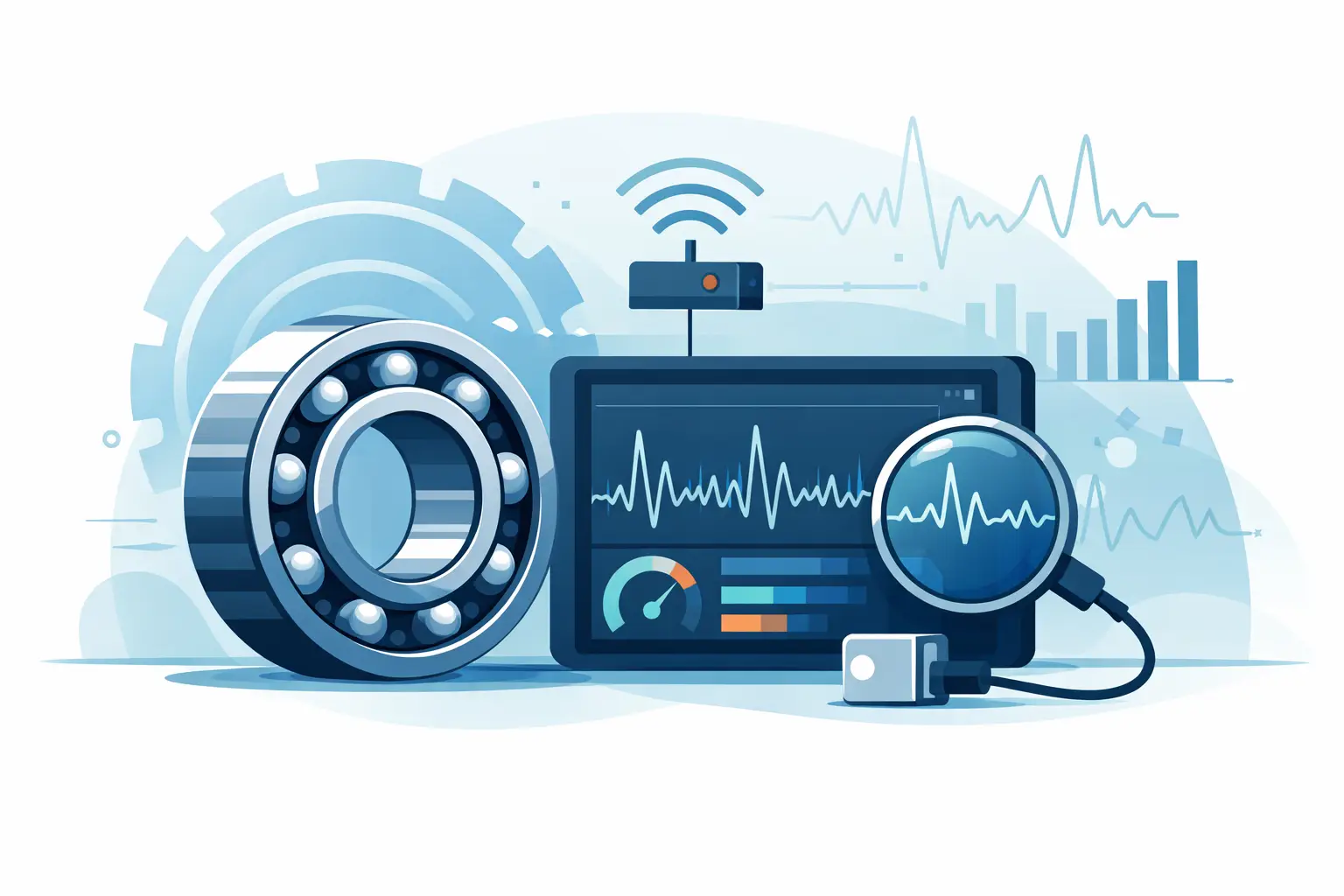
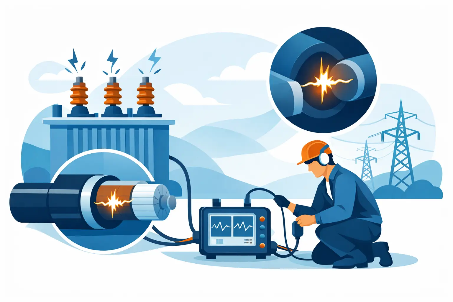
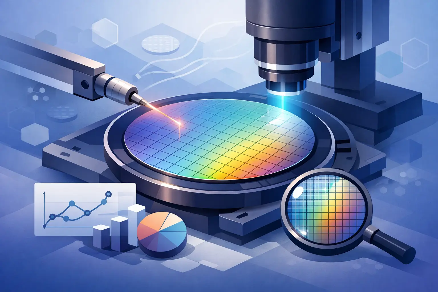
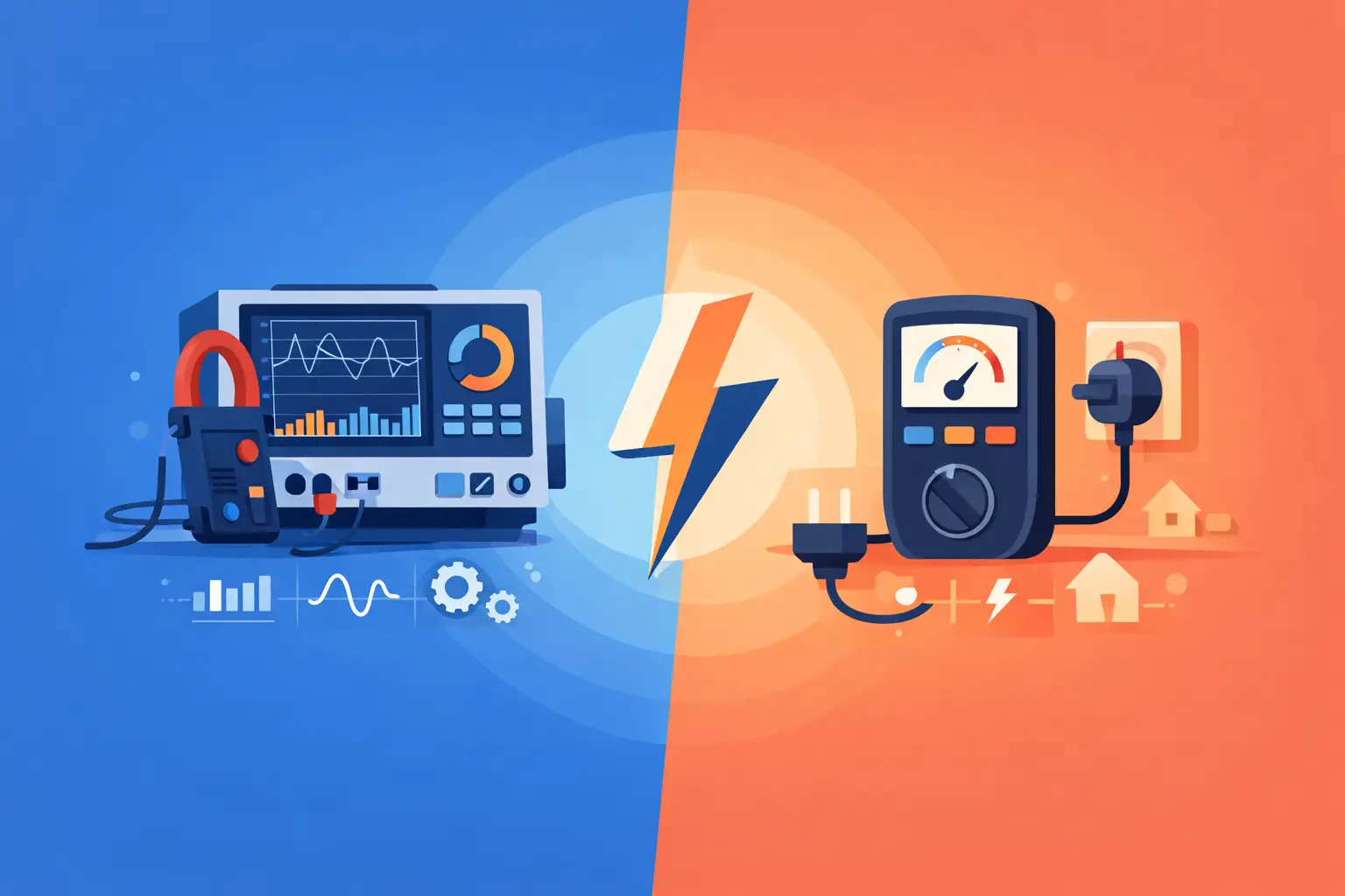
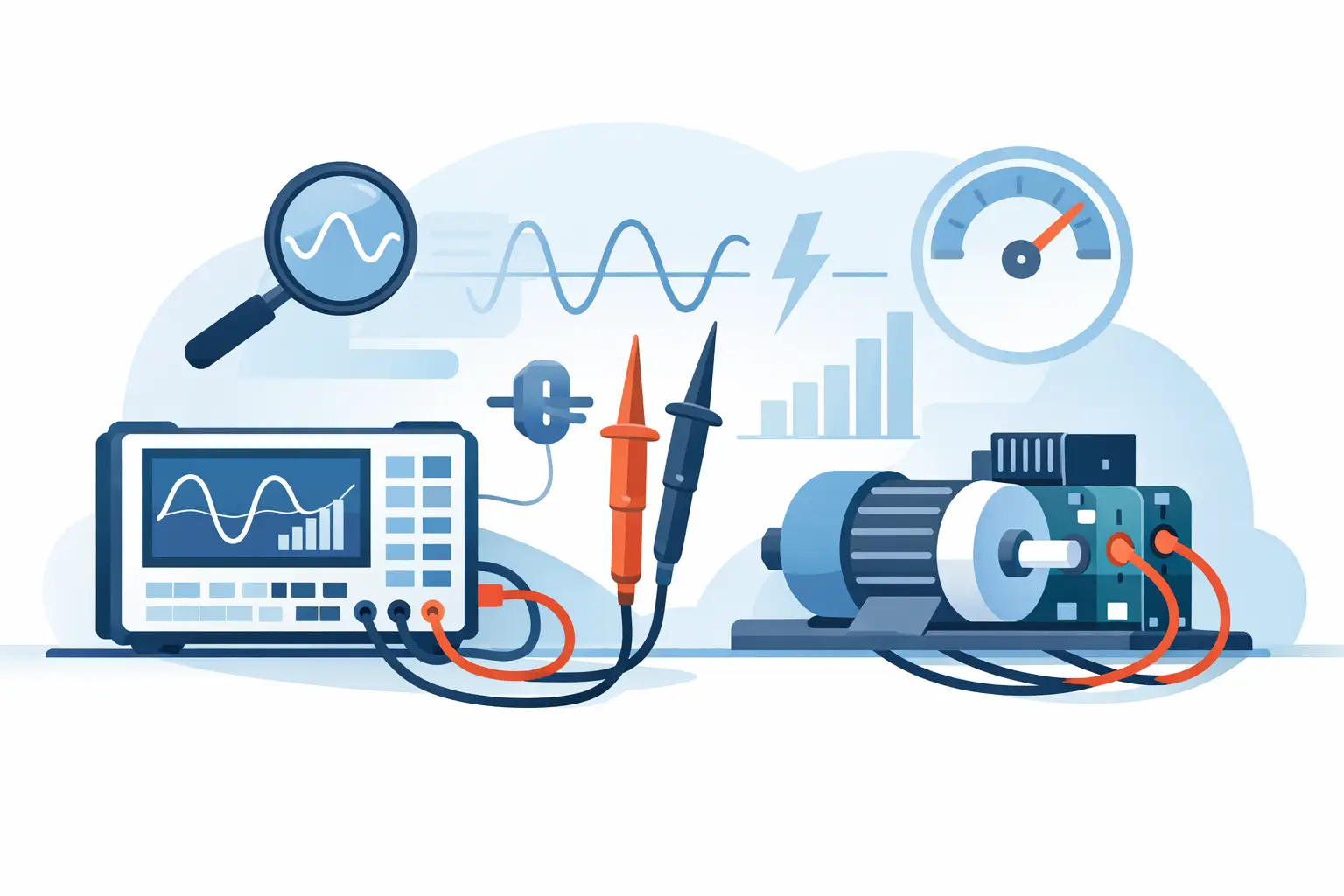
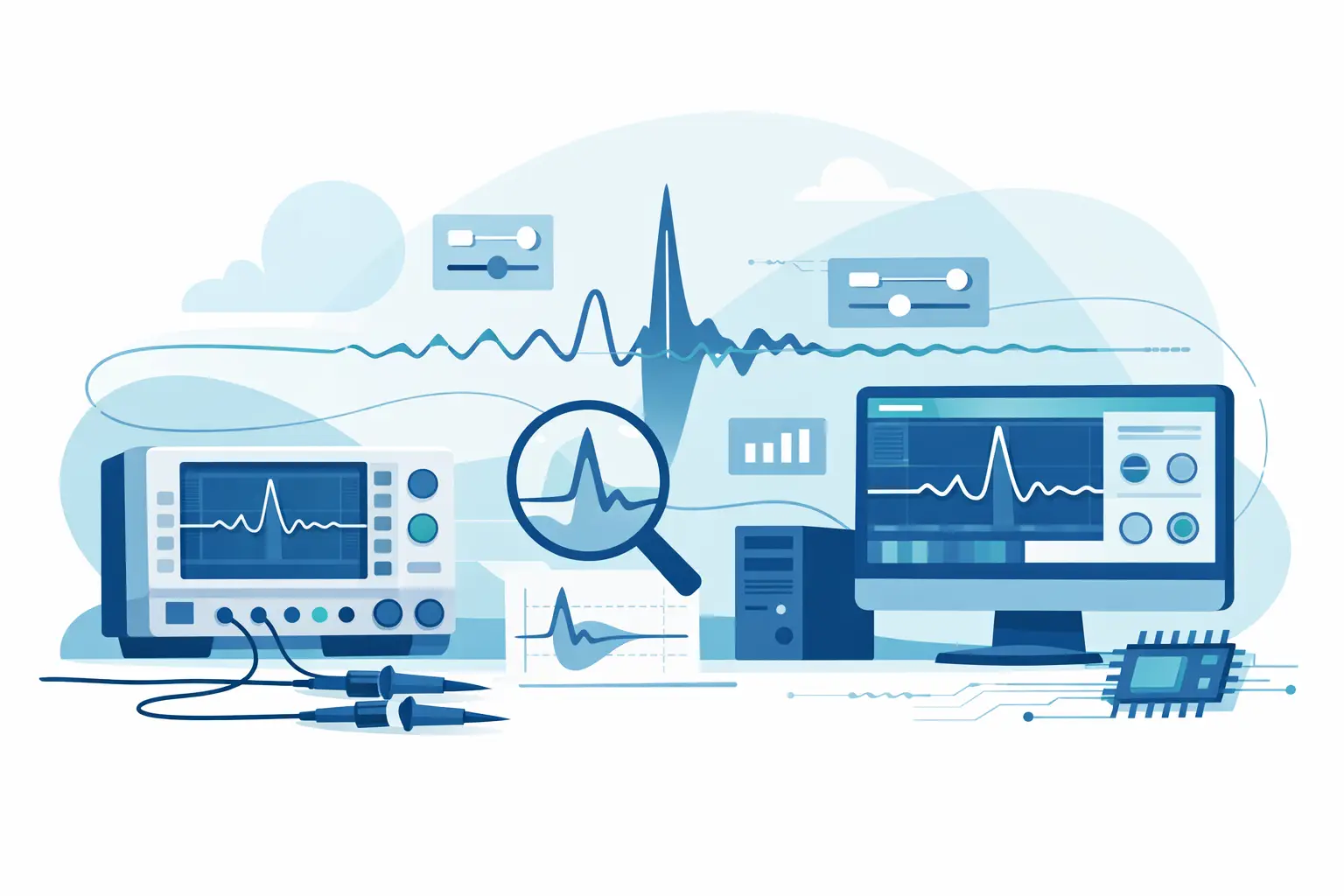
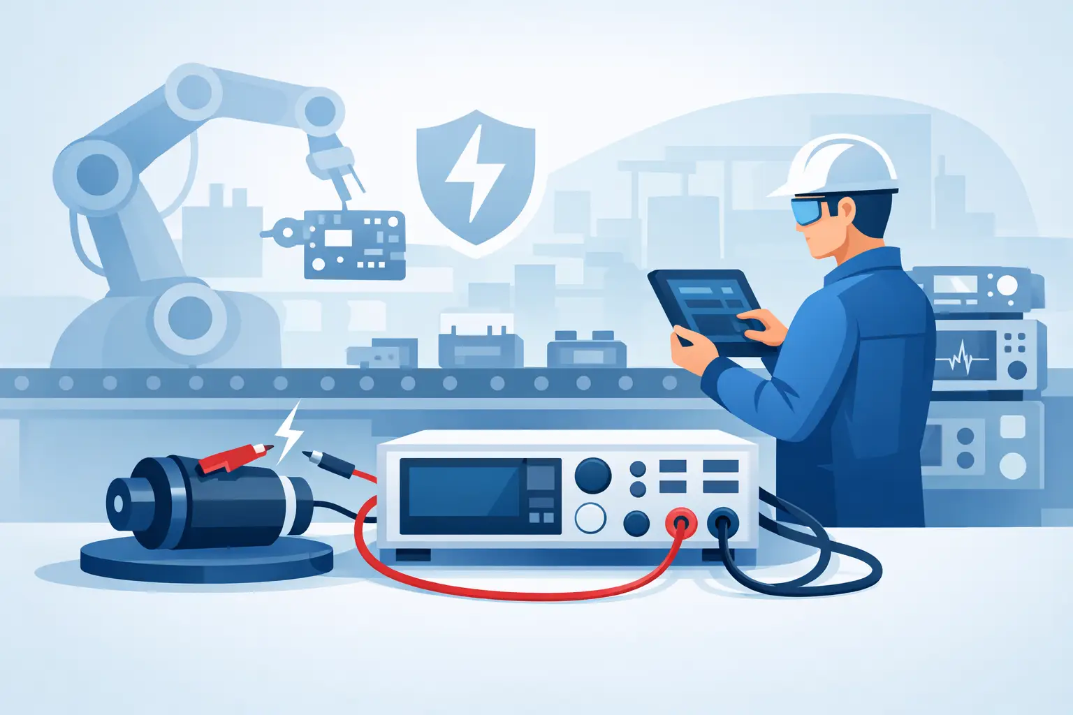
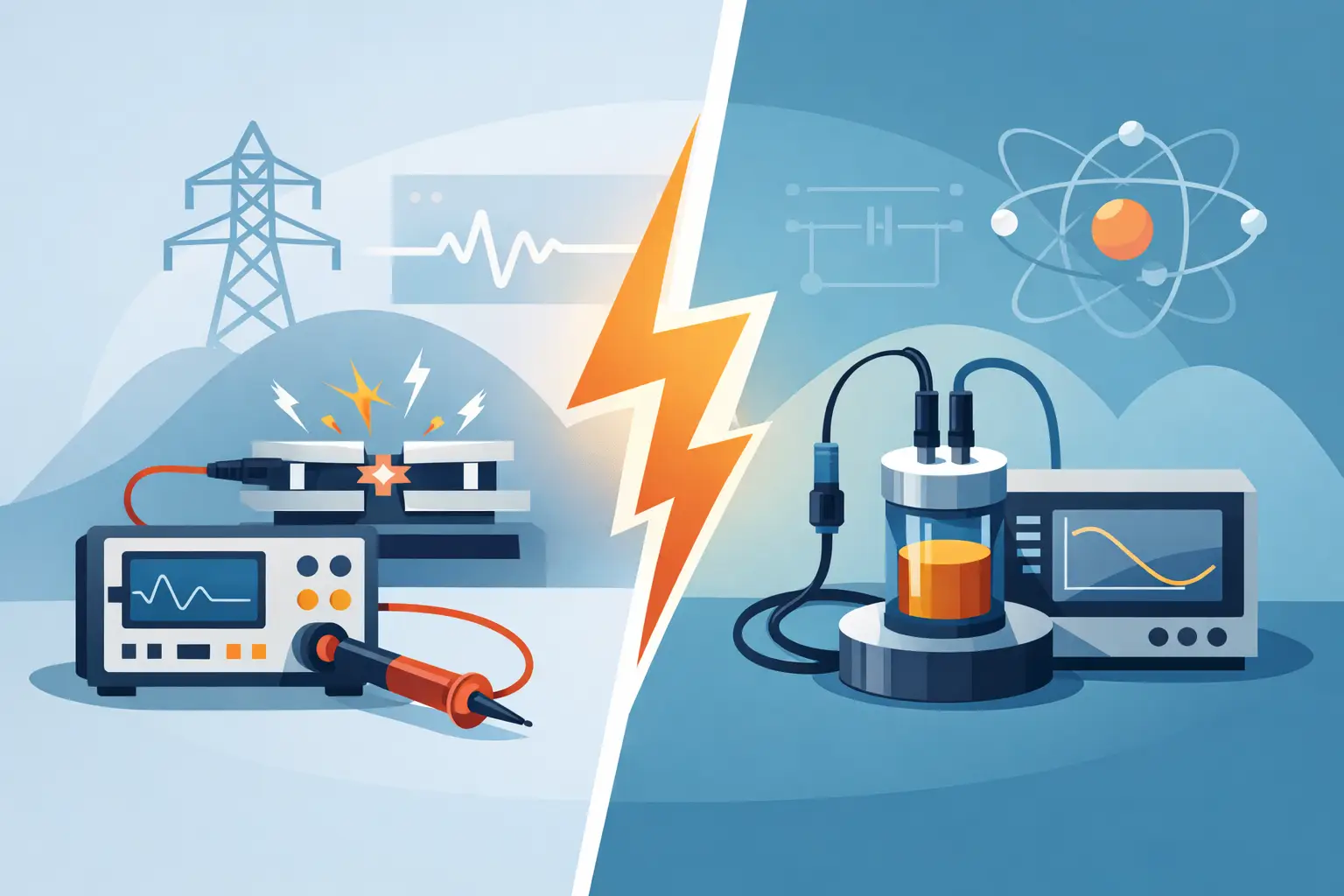
A transient that appears once per power cycle, an RF burst captured over milliseconds, and a prototype board debugged at the bench may all require high-speed waveform acquisition. They do not necessarily require the same instrument. The practical distinction in digitizers versus oscilloscopes is not simply whether each device samples voltage. It is whether the measurement task is centered on immediate visual troubleshooting or on acquiring defensible waveform data within a larger test system.
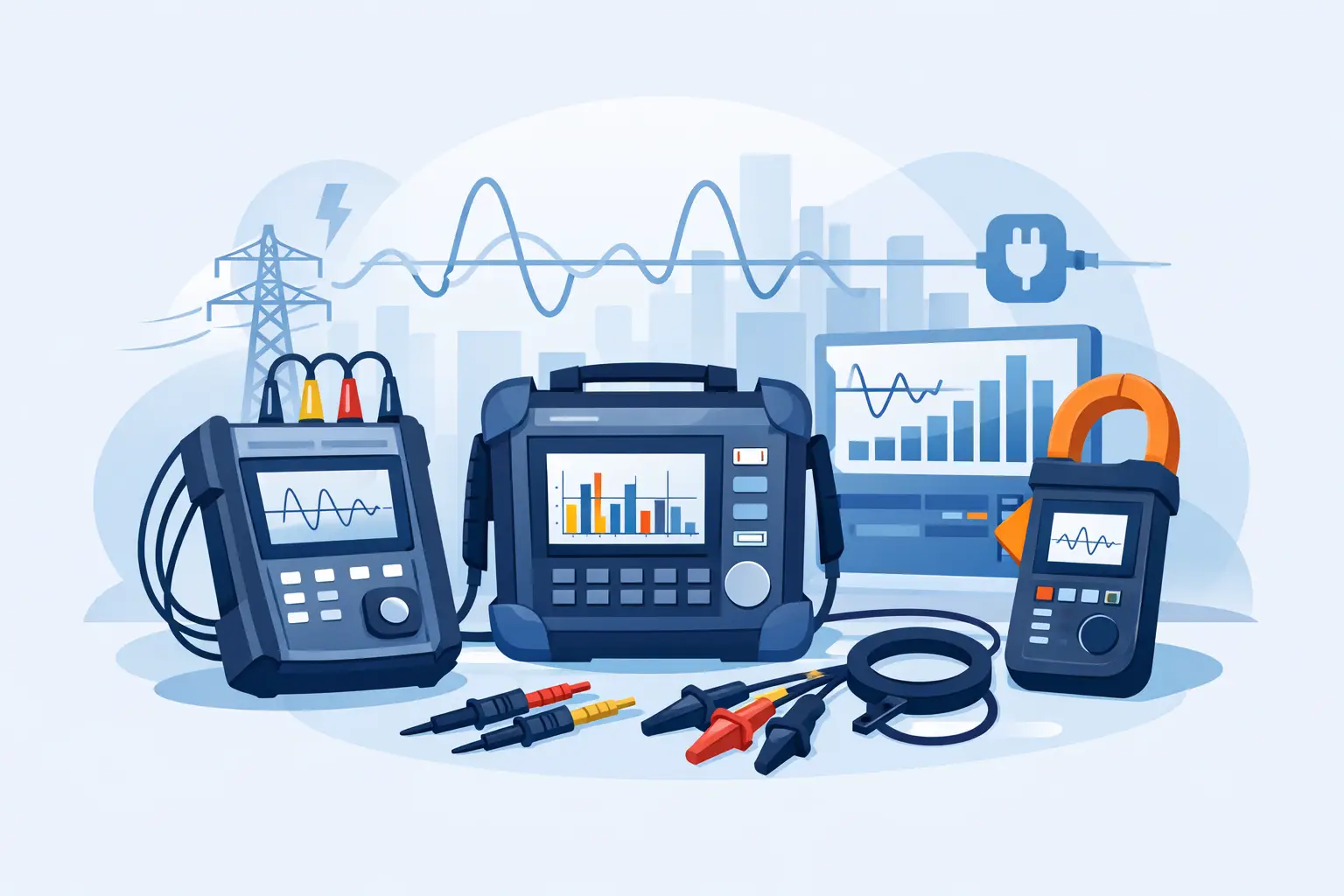
Both instruments use analog front ends, sampling clocks, analog-to-digital converters, acquisition memory, and triggering. A modern oscilloscope may also provide deep memory, protocol decoding, automated measurements, and sophisticated math. A high-speed digitizer may provide exceptional sample rates, channel density, synchronization, and continuous data transfer. The correct choice depends on the signal, the event of interest, the required record length, and what must happen to the data after capture.
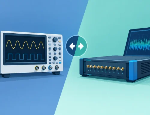
Digitizers Versus Oscilloscopes: The Core Difference
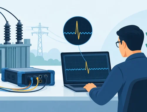
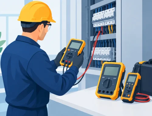
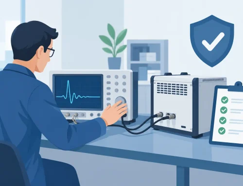
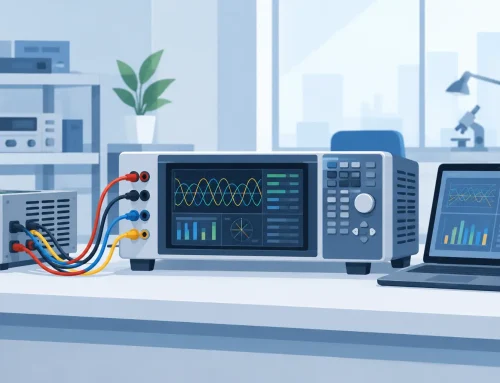
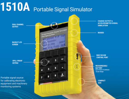
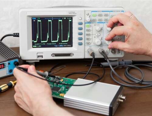
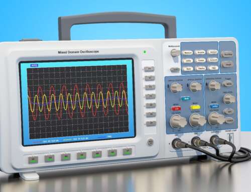
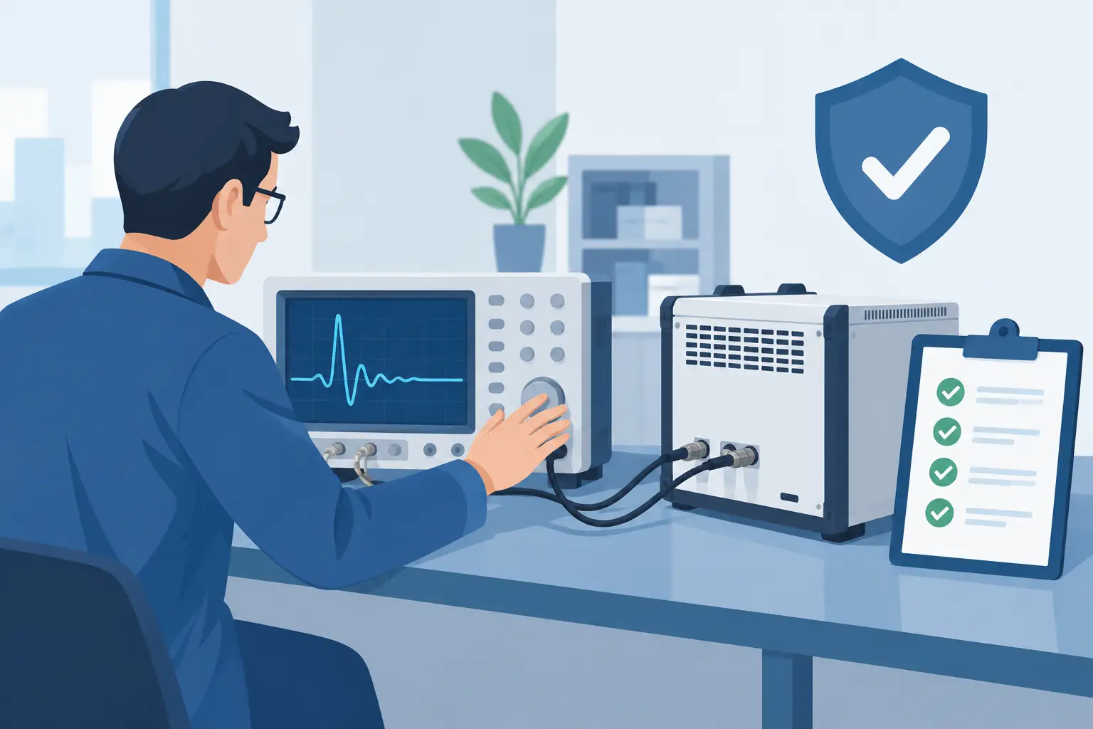
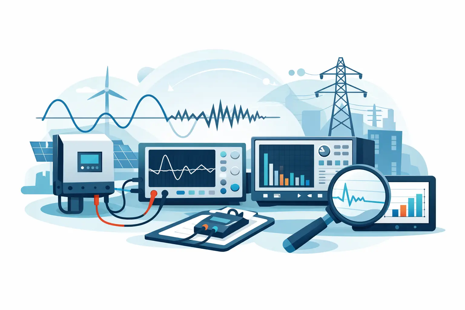
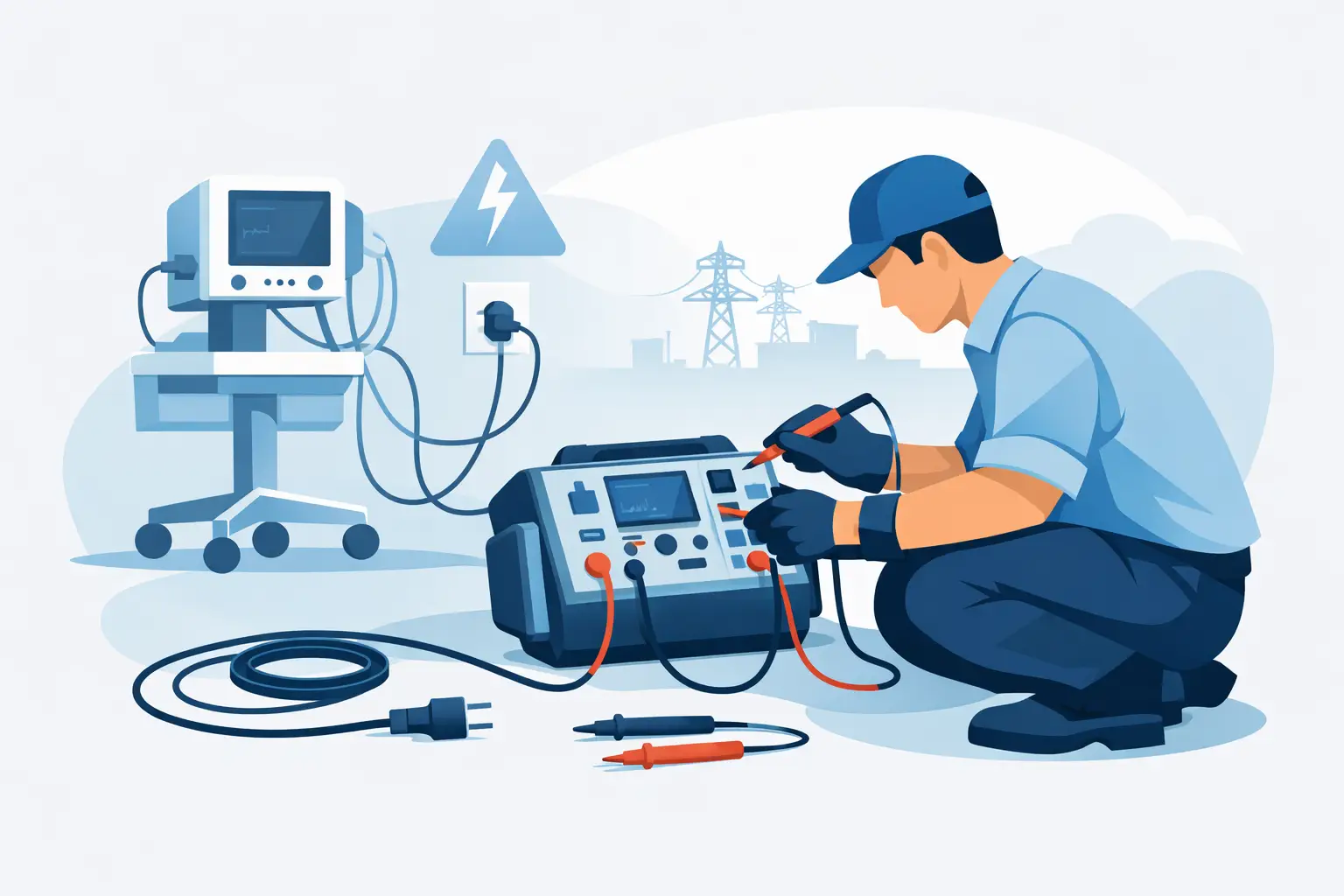
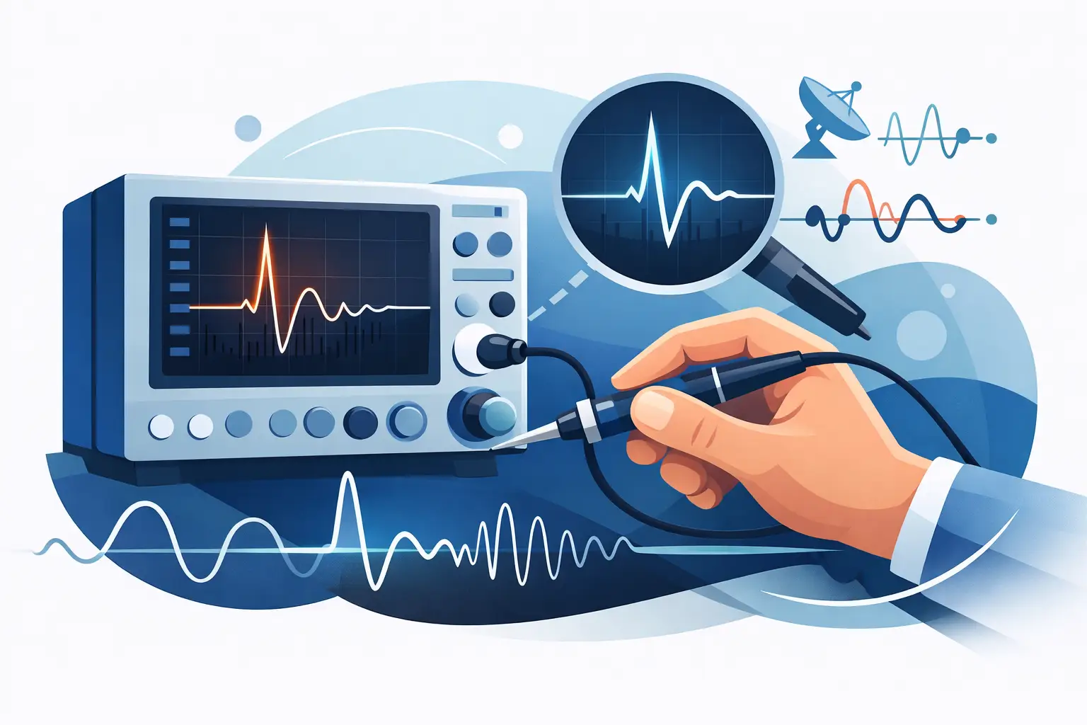
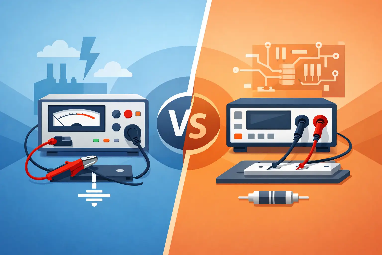
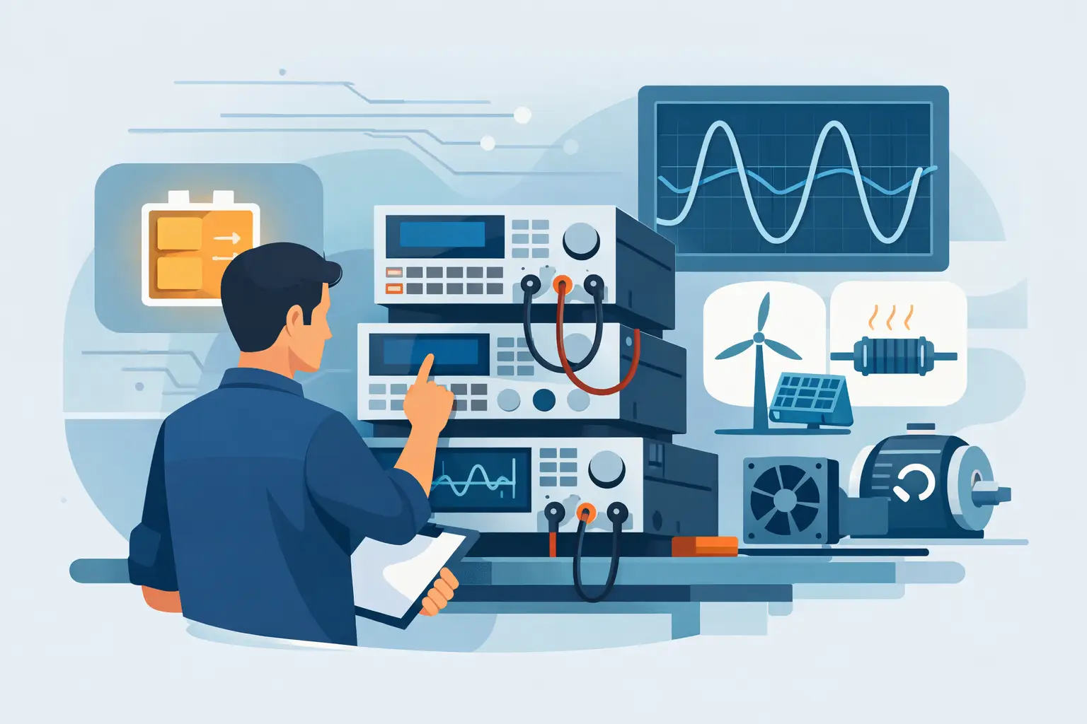
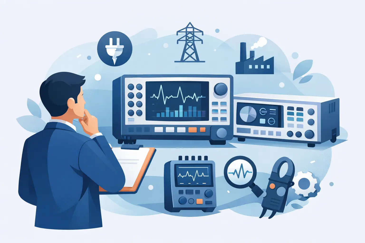
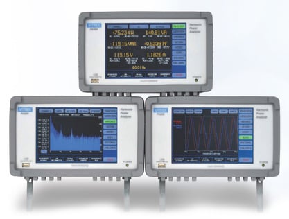
An oscilloscope is generally designed as a self-contained diagnostic instrument. Its integrated display, front-panel controls, trigger controls, measurement functions, and analysis tools allow an engineer to connect a probe, observe a signal, isolate an anomaly, and make decisions quickly. This workflow is valuable during design verification, field troubleshooting, repair, and exploratory lab work where the test conditions may change frequently.
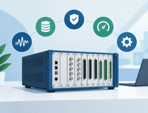
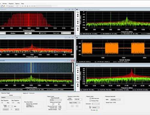
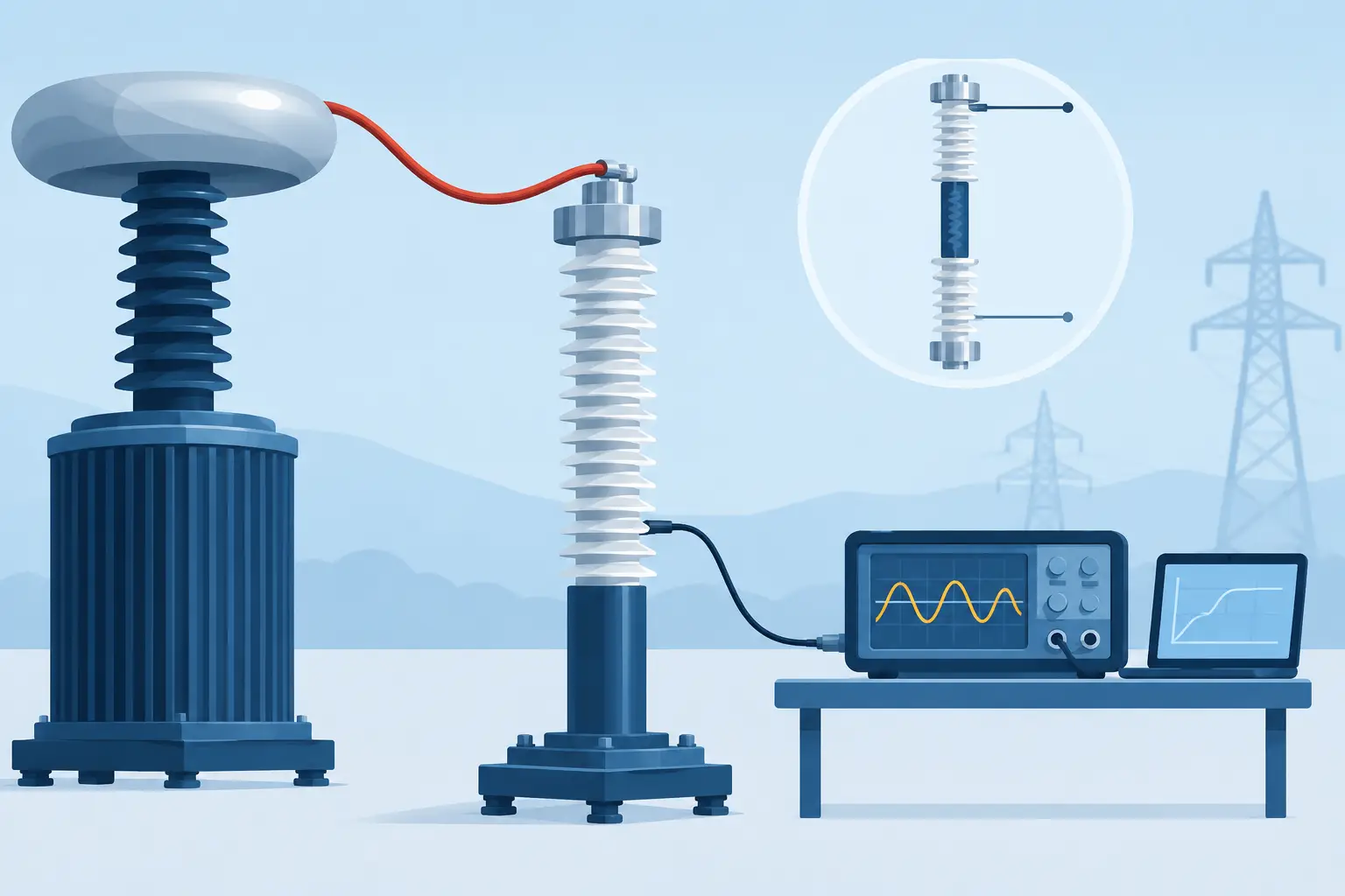
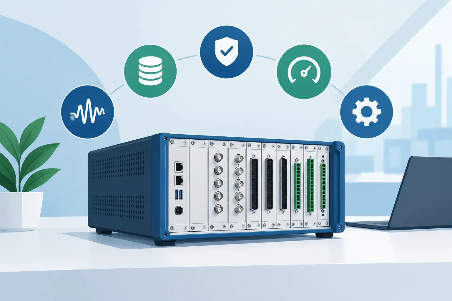
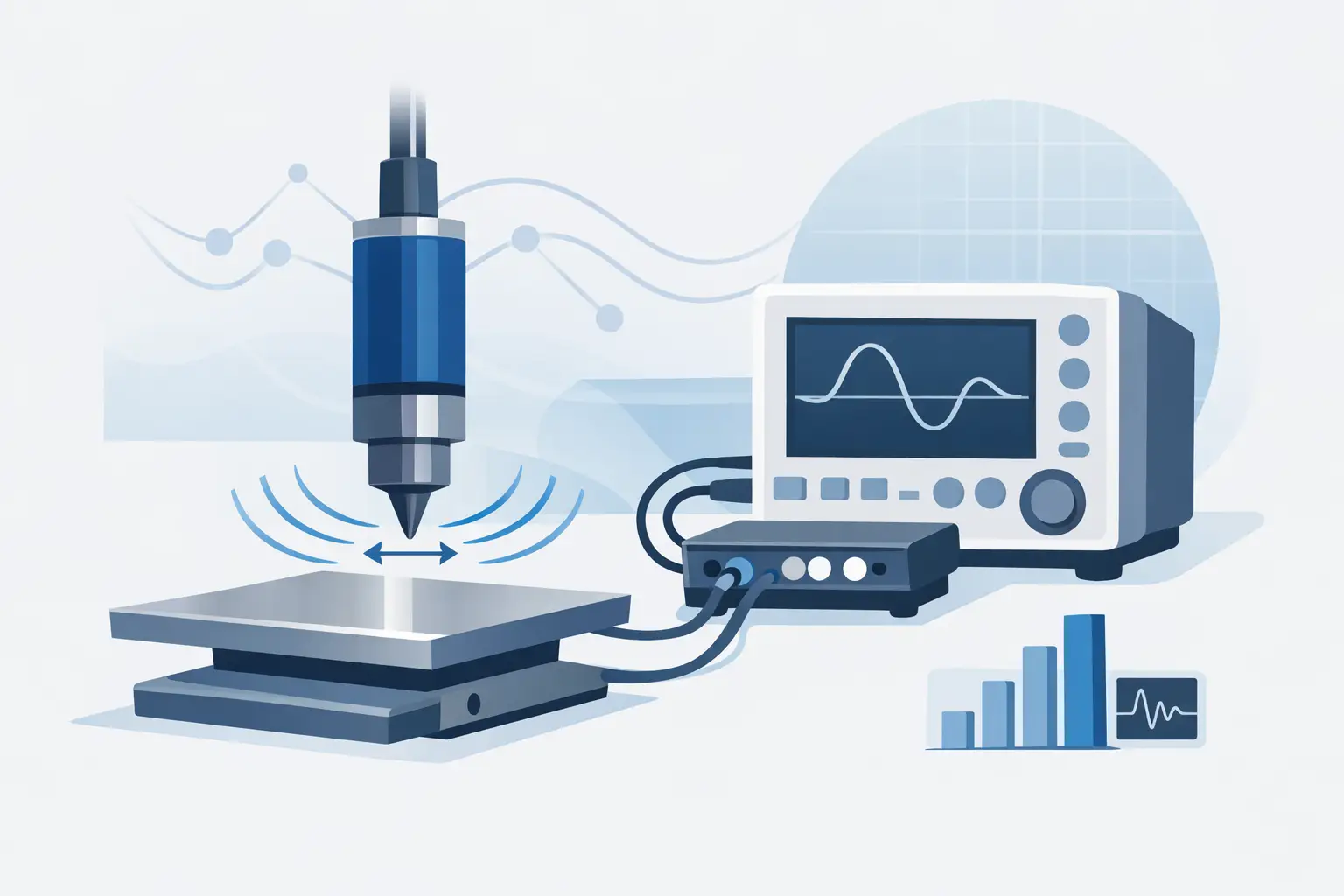
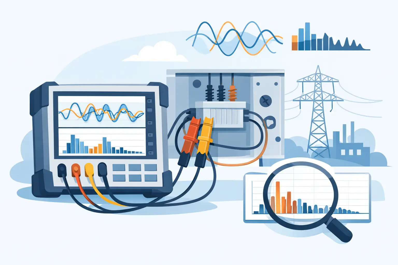
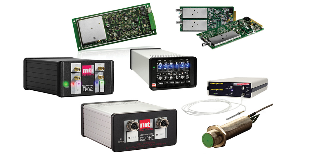
A digitizer is generally designed as an acquisition engine. It is commonly installed in a PCIe, PXI, PXIe, or other computer-based platform, where software controls configuration, triggering, acquisition, storage, and post-processing. Rather than making the instrument display the primary interface, a digitizer gives the host system direct access to sampled data for custom analysis, automated test sequences, or long-duration recording.
This distinction matters because instrument selection affects more than the waveform visible on screen. It affects test throughput, data architecture, automation effort, synchronization options, and the traceability of the resulting measurement process.
When an Oscilloscope Is the Better Engineering Tool
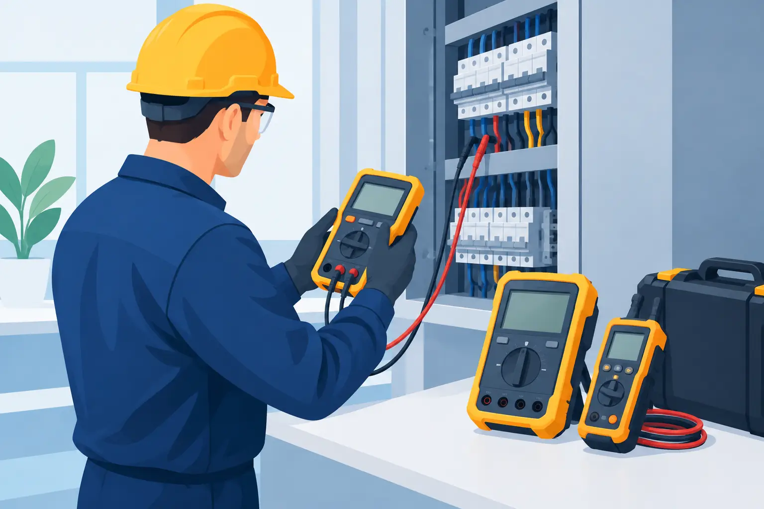
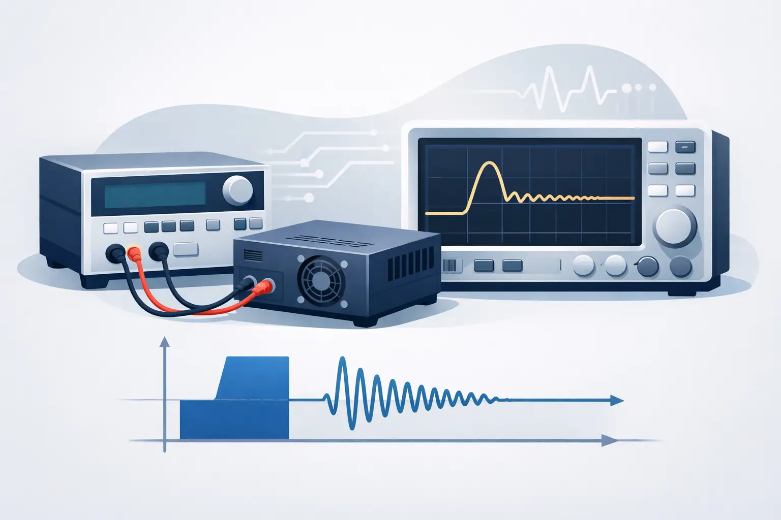
Oscilloscopes are typically the efficient choice when the engineer needs immediate visibility and interaction. A bench scope can reveal ringing on a switching node, intermittent timing violations, unexpected overshoot, or a malformed serial signal without requiring a software application to be developed first.
The display and user interface are a meaningful advantage, not a convenience feature. Engineers can adjust vertical scale, time base, triggering, persistence, and measurement settings while developing an understanding of an unfamiliar signal. Built-in waveform math, FFT functions, mask testing, and protocol decode can shorten the path from symptom to root cause.
Oscilloscopes also work well when the measurement is episodic. If an engineer needs to capture a startup transient, characterize a pulse edge, or verify timing across a few channels, the acquisition does not necessarily need to be integrated into a production or unattended workflow. The ability to place an instrument on a bench and begin measuring within minutes is often the right answer.
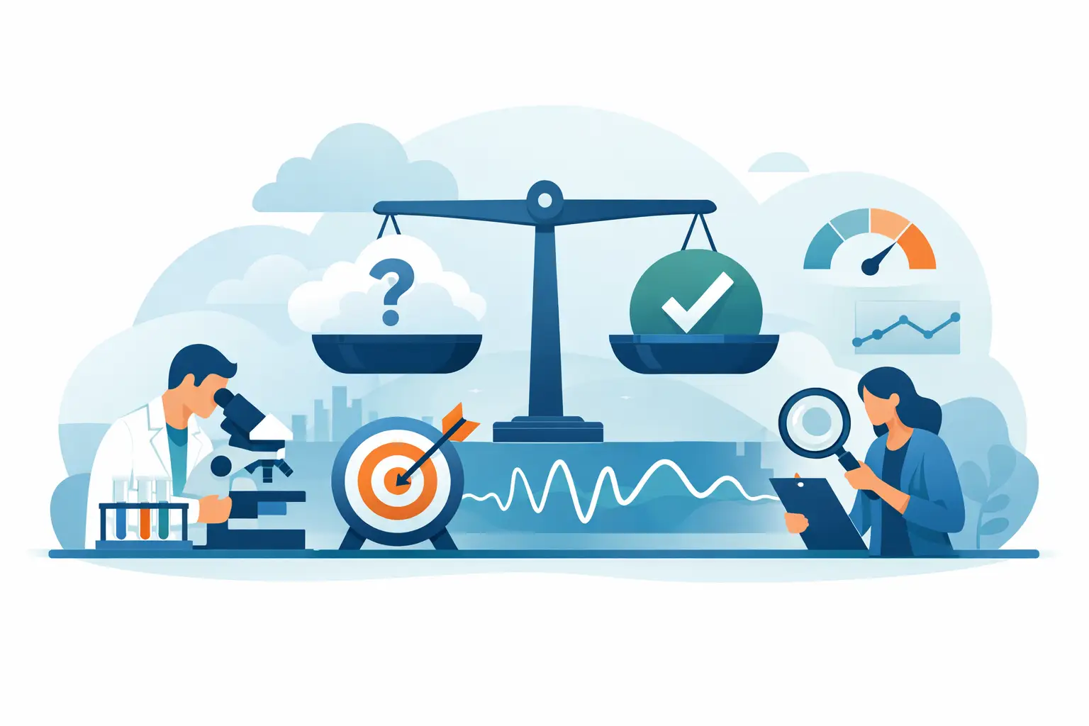
That said, a scope specification should still be evaluated carefully. Bandwidth, sample rate, memory depth, effective number of bits, input noise, trigger sensitivity, and probe selection all determine whether the captured waveform supports the intended conclusion. A fast scope with inadequate vertical resolution or excessive noise may not be appropriate for low-level signal characterization.
When a Digitizer Is the Better Choice
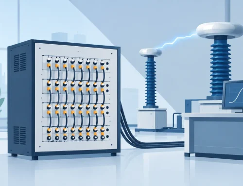
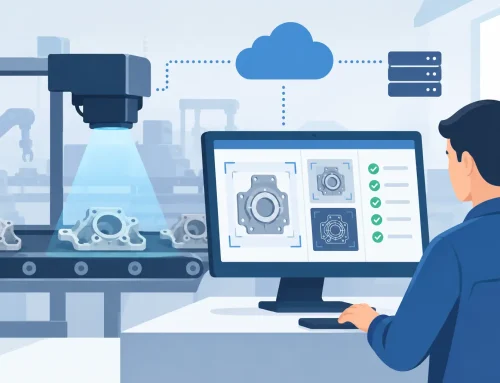
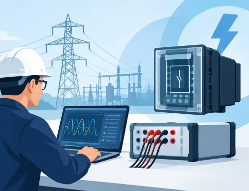
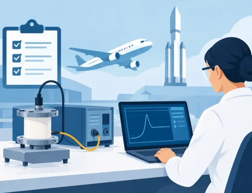
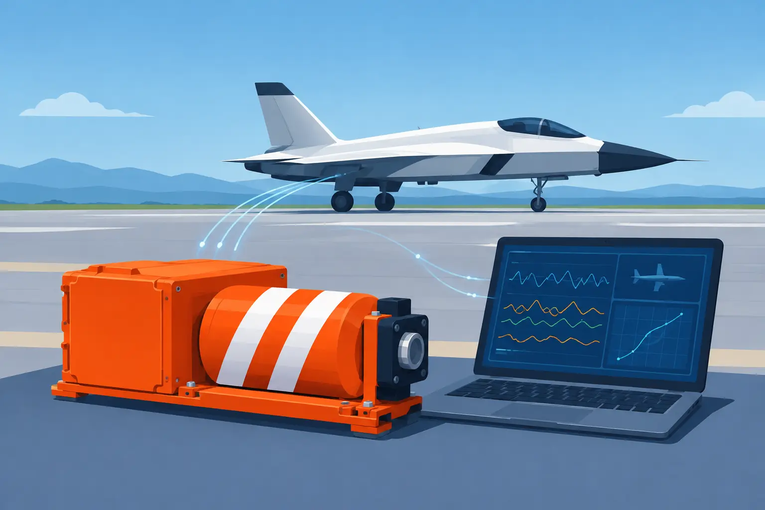
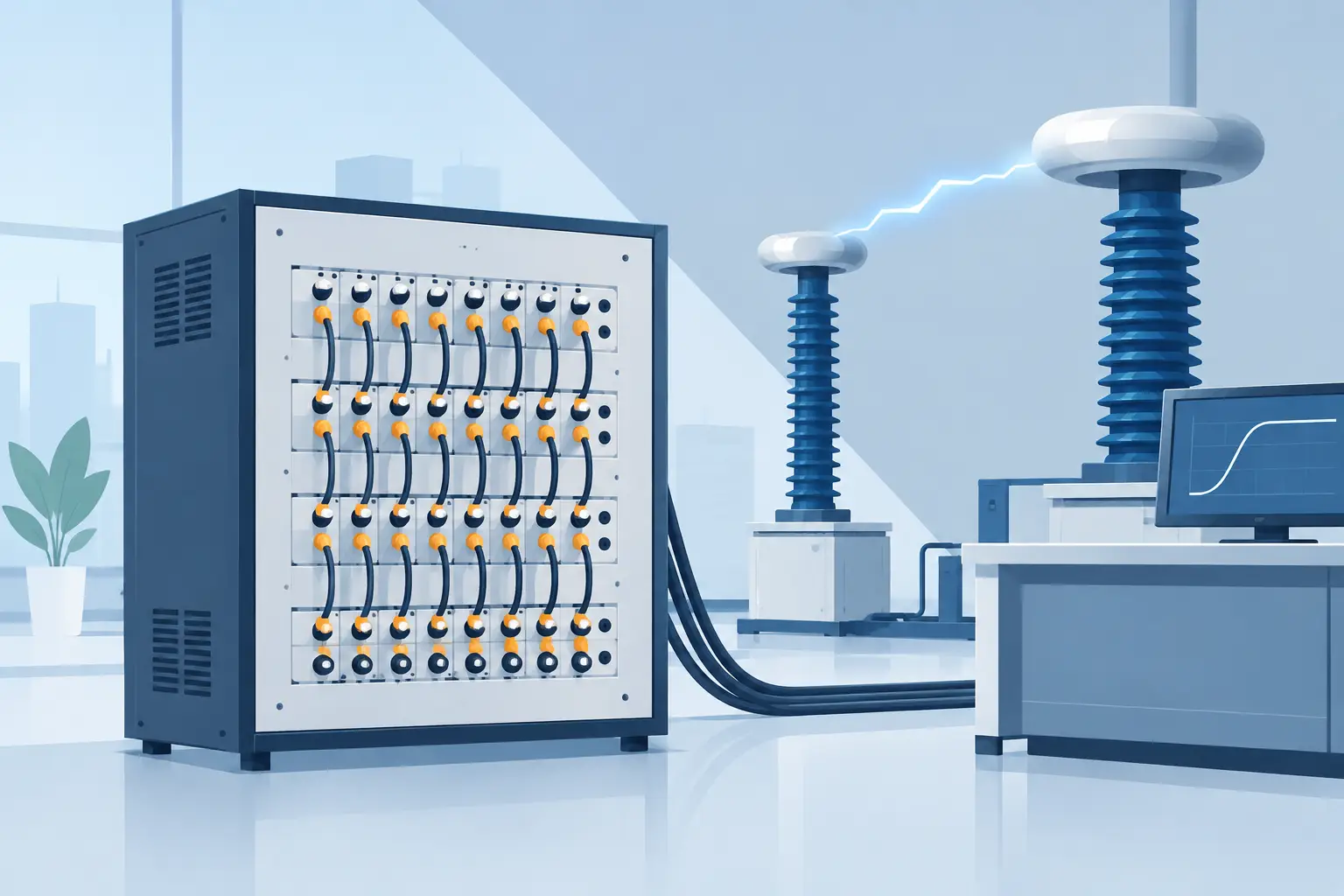
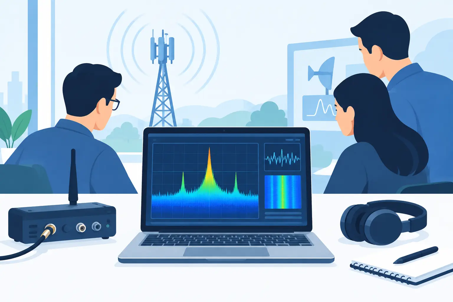
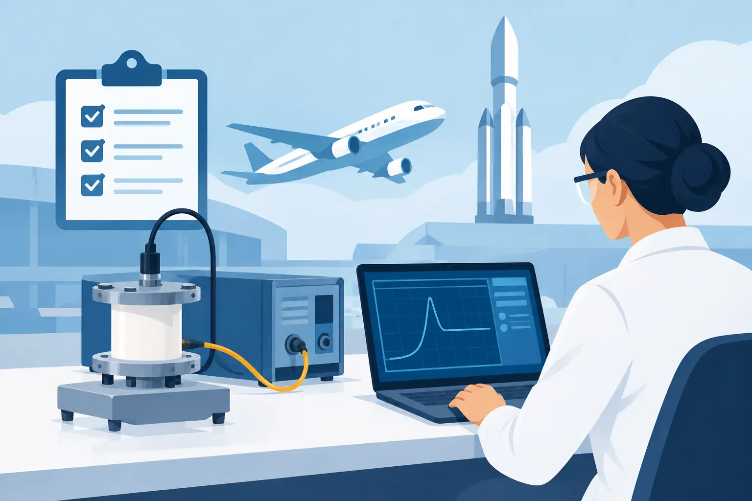
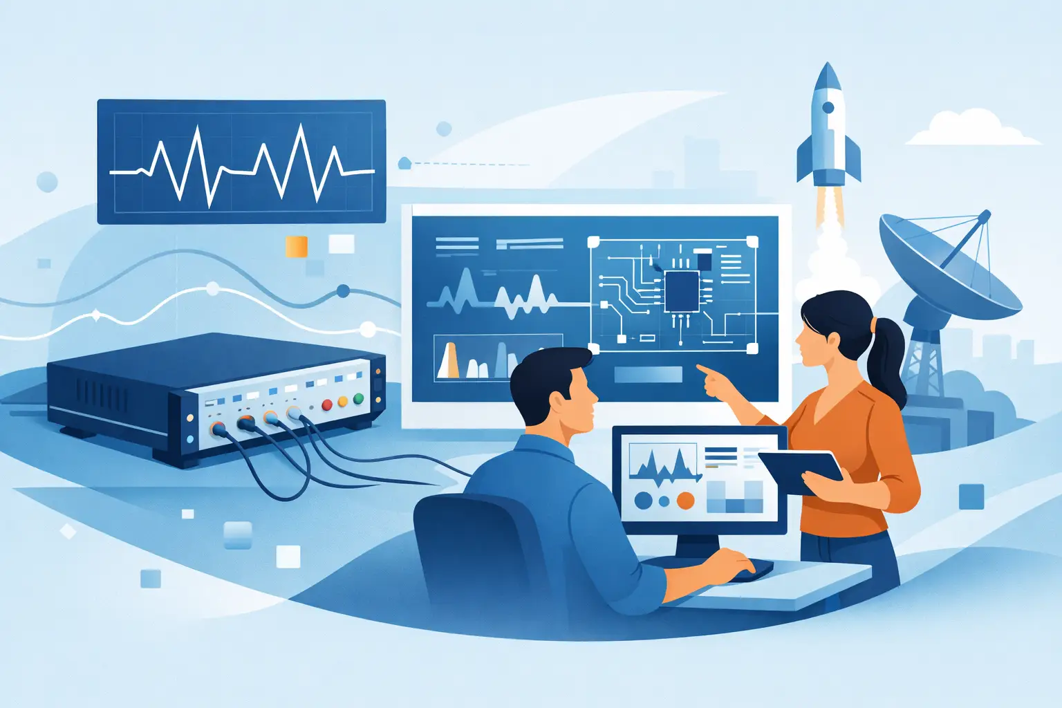
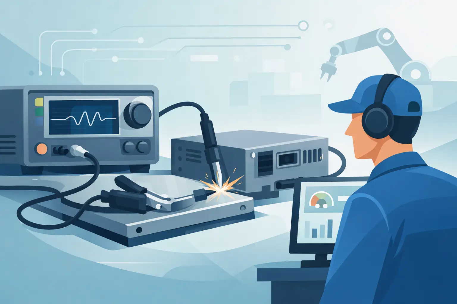
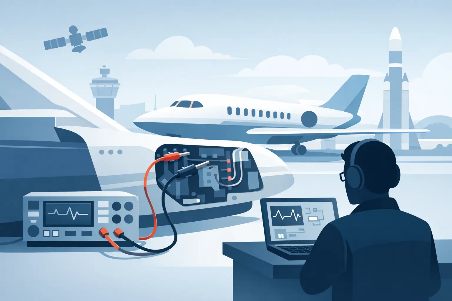
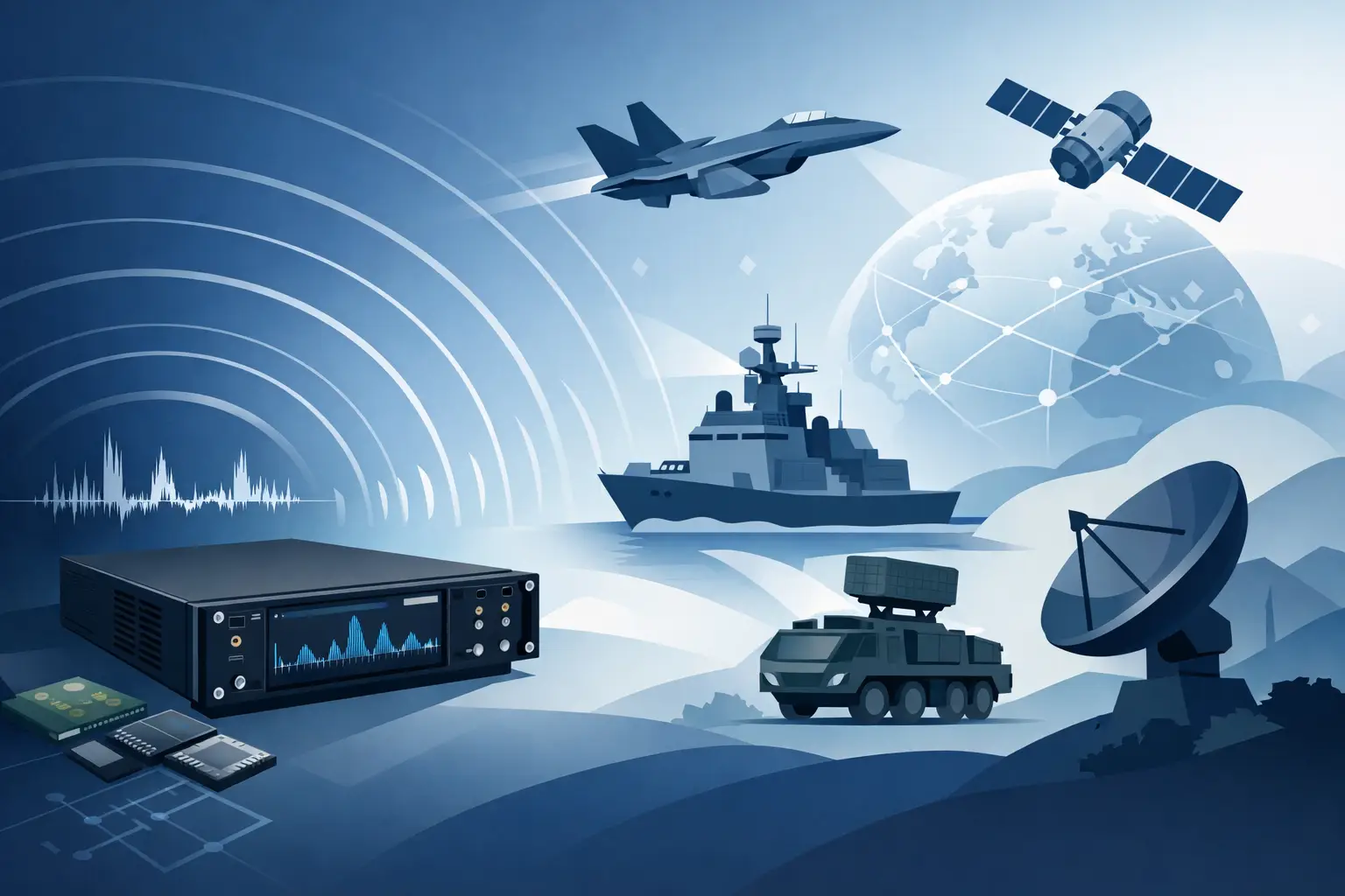
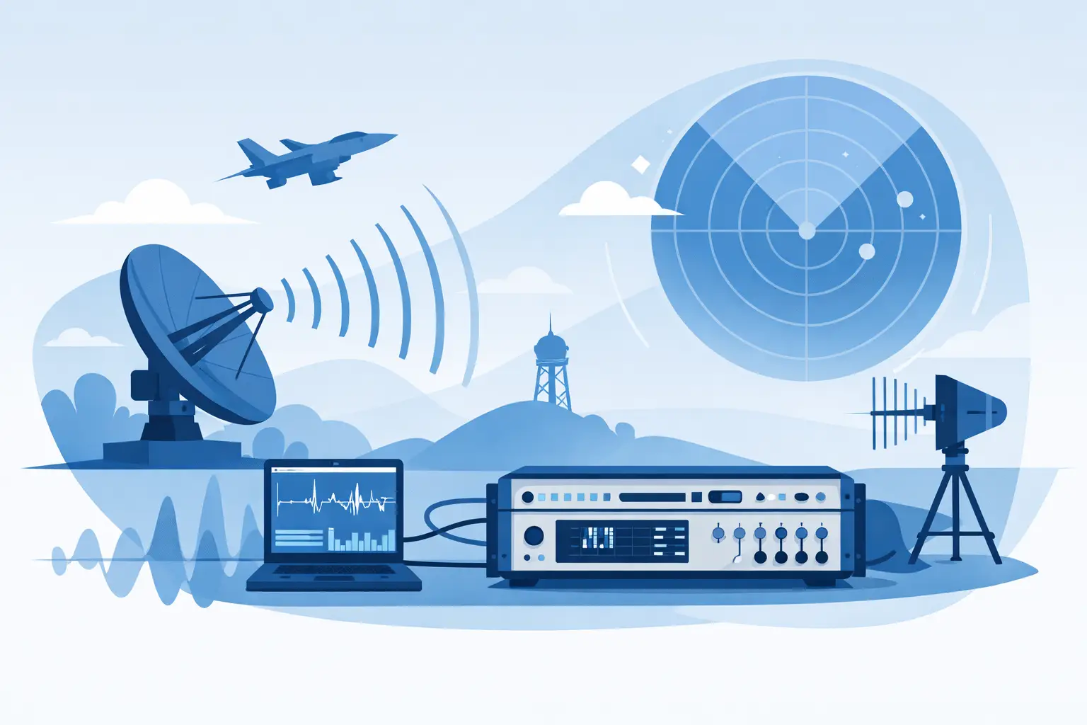
A digitizer becomes compelling when waveform data is part of a repeatable system rather than a one-time troubleshooting session. This includes automated test stands, high-energy physics experiments, radar and communications recording, power-conversion characterization, aerospace qualification, and data acquisition systems that must capture data over extended periods.
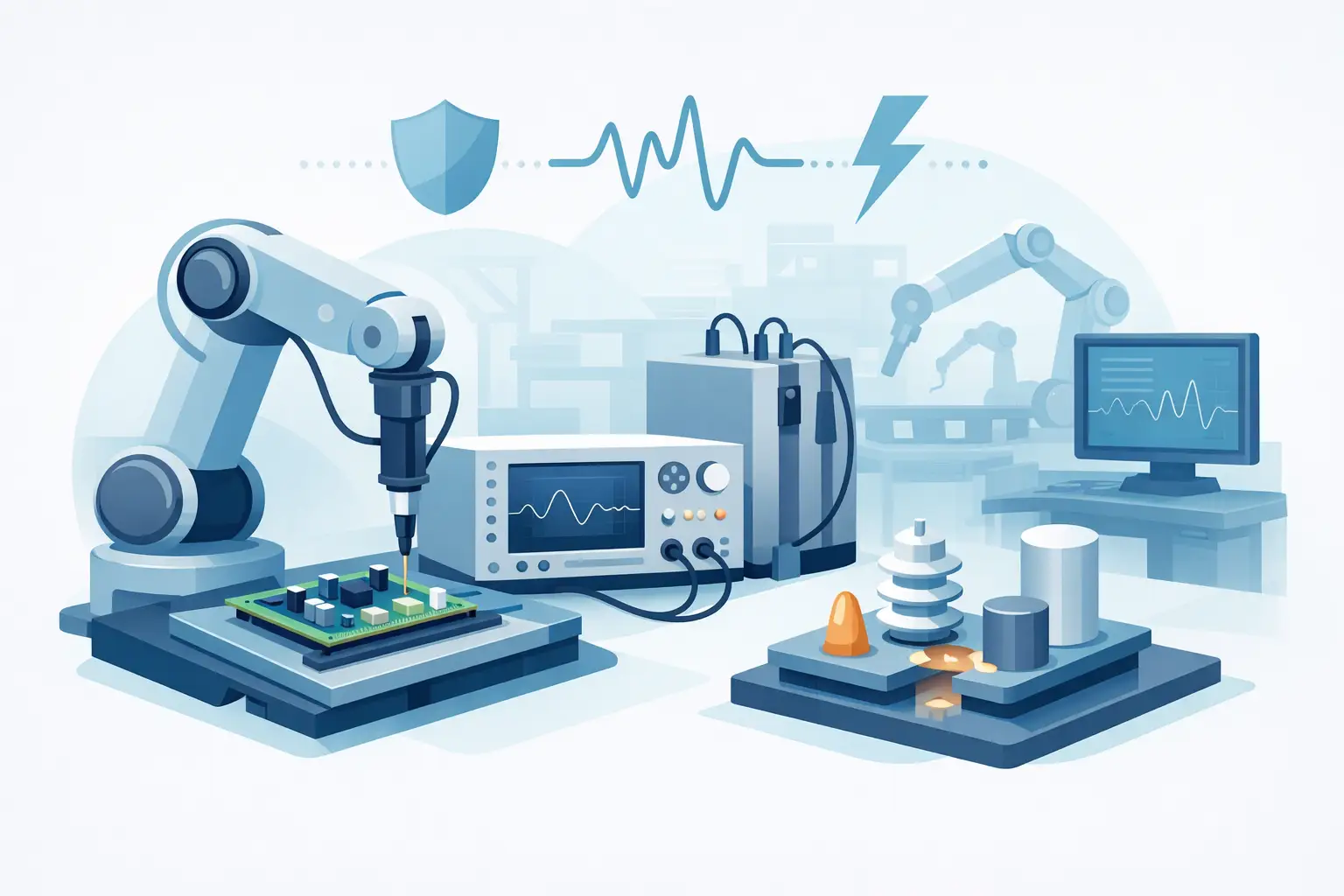
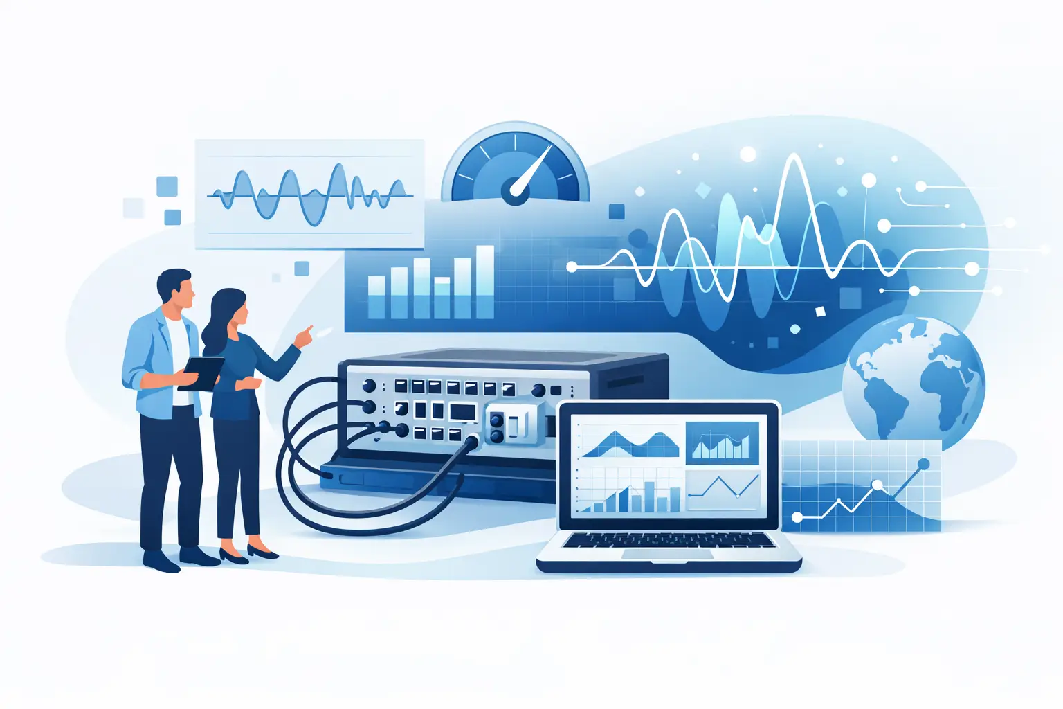
The primary benefit is control over the acquisition and analysis pipeline. Software can configure channels, arm the trigger, acquire records, perform calculations, compare results against limits, store raw data with test metadata, and generate pass/fail outcomes without operator intervention. This architecture supports consistency between units, shifts, test locations, and test revisions.
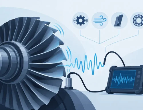
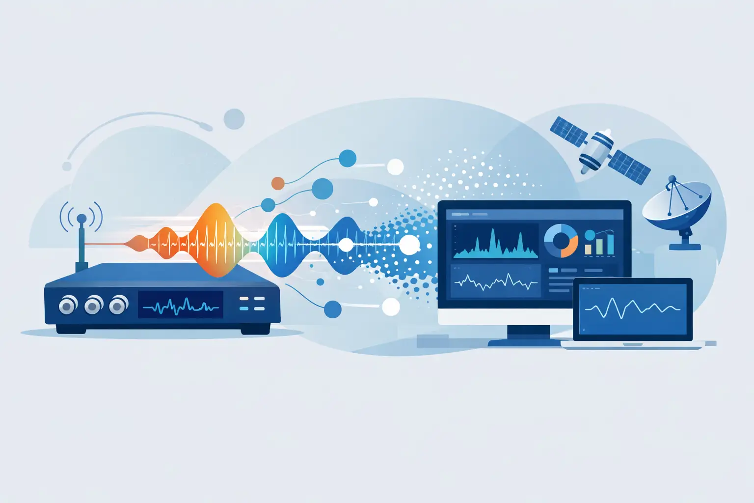
High-speed digitizers are also well suited to applications that require large waveform records or sustained transfer of data to host memory or disk. The useful question is not merely, “How deep is the onboard memory?” It is, “How much data must be captured, at what rate, for how long, and where will it be processed?” A system that captures isolated bursts has different requirements from one that records continuous IF data or repeated transient events.
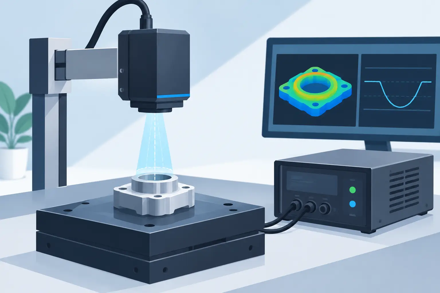
For many applications, synchronization is equally important. Multi-channel digitizers may support shared clocks, trigger distribution, time stamping, and deterministic alignment across channels or chassis. In a test system, channel-to-channel timing integrity can matter more than the convenience of an integrated display. A digitizer platform can also be paired with custom fixtures, switching hardware, motion systems, environmental chambers, and test executive software.
Compare the Specifications That Affect Measurement Integrity
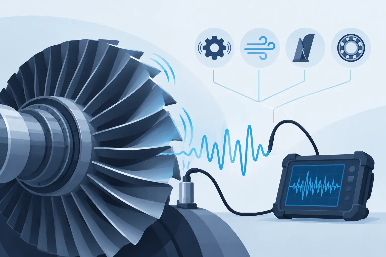
Sample rate and analog bandwidth are often the first specifications considered, but they do not stand alone. Sample rate determines the spacing between acquired points. Bandwidth describes the frequency range over which the front end can accurately pass signal content within its specified response. For fast edges, transient capture, and broadband signals, both must be sufficient for the phenomenon being measured.
Vertical resolution deserves equal attention. An 8-bit converter provides 256 nominal codes, while higher-resolution architectures can better distinguish small signal changes within the input range. Actual performance depends on noise, linearity, front-end design, and clock quality, so effective number of bits and signal-to-noise ratio are often more informative than nominal converter resolution alone.
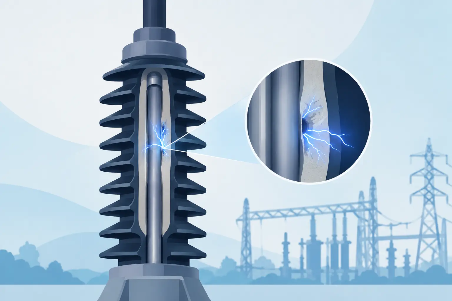
Triggering should be matched to the event being studied. Edge triggering may be adequate for repetitive signals. More demanding work may require pulse-width, pattern, window, external, or software-controlled triggering. In rare-event capture, pretrigger memory and low trigger jitter can determine whether the system records the condition that caused a failure or only its aftermath.
Memory depth defines the time span available at a selected sample rate. A simple relationship applies: record length divided by sample rate equals capture duration. At 1 GS/s, a 1 million-sample record spans approximately 1 ms. Engineers should calculate this requirement early, particularly when they need high resolution across a long event. Reducing sample rate to extend capture time can hide fast anomalies; increasing the sample rate without sufficient memory can shorten the observation window.
The input interface also matters. Input range, impedance, coupling, overload recovery, isolation requirements, and sensor compatibility should be evaluated before selecting an instrument. A digitizer that integrates efficiently into software may still be a poor fit if the front end cannot accommodate the expected signal amplitude or source impedance. Similarly, probe loading and grounding practices can alter the very waveform an oscilloscope is intended to observe.
System Integration Changes the Decision
For an automated environment, the software development kit is part of the instrument. Drivers, APIs, operating-system support, example code, buffer management, trigger control, and data formats affect deployment time and long-term maintainability. A digitizer should be assessed as a hardware and software subsystem, not as a standalone board specification.
Data volume also requires planning. High sample rates across multiple channels produce large files quickly. Engineers need to define whether raw data will be retained, reduced to calculated parameters, streamed to local storage, transferred over a network, or processed in real time. The answer drives bus selection, computer configuration, storage throughput, and analysis architecture.
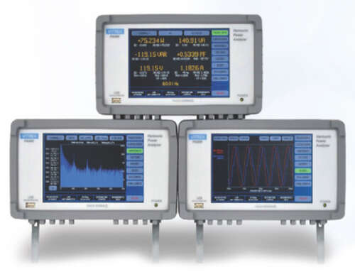
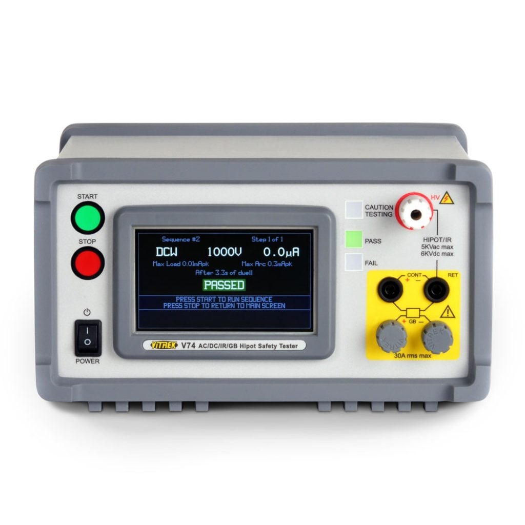
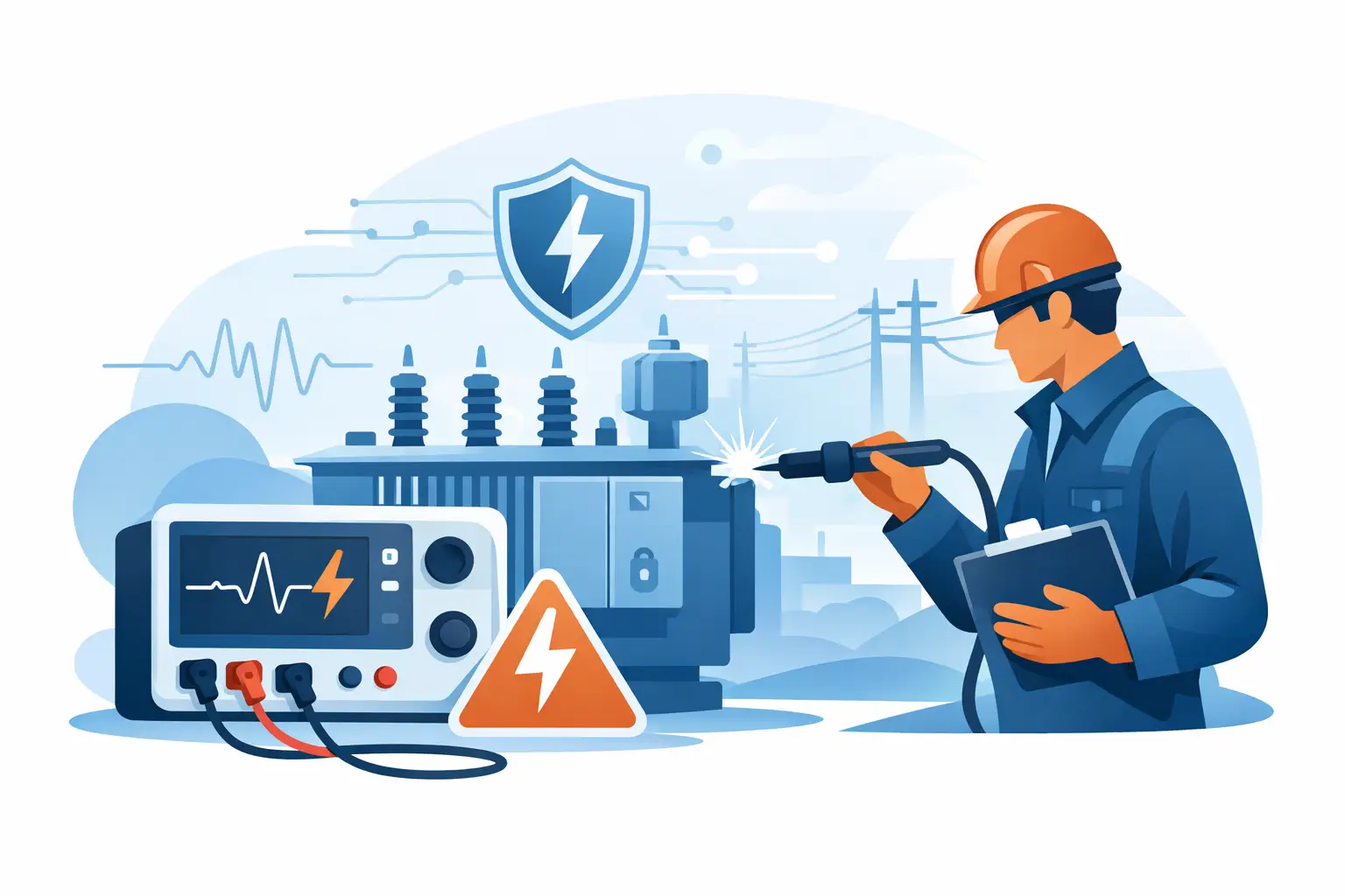
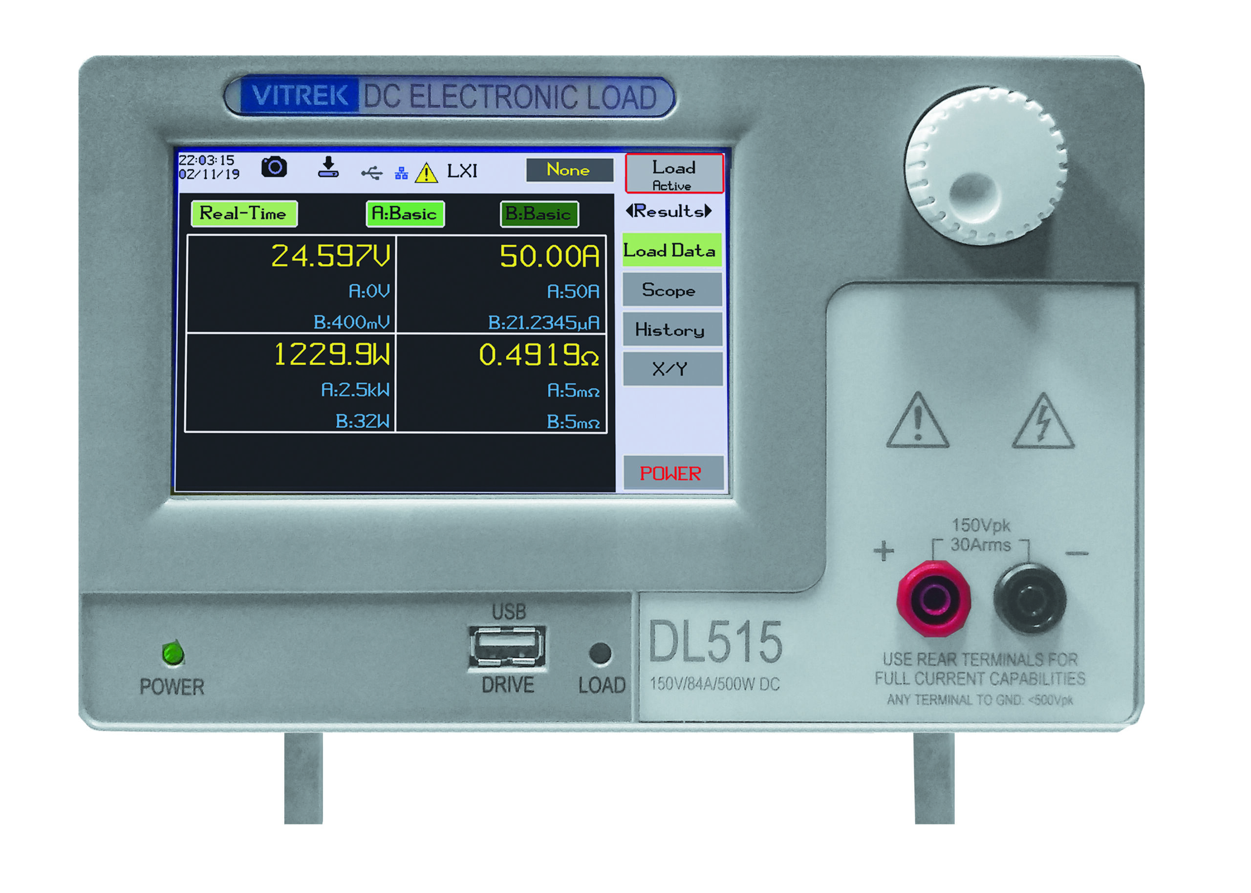
Calibration and traceability cannot be treated as administrative details in regulated or performance-critical programs. Instrument accuracy, calibration interval, environmental conditions, uncertainty requirements, and documentation practices should align with the test plan. For organizations building repeatable measurement infrastructure, suppliers such as Vitrek support this need through application-focused instrumentation, technical support, and calibration-oriented services.
A Practical Selection Method
Start by defining the event, not the instrument category. Describe its frequency content, amplitude, duration, repetition rate, trigger condition, and required measurement uncertainty. Then determine whether an engineer needs to interact with the signal in real time or whether the data must feed an automated workflow.
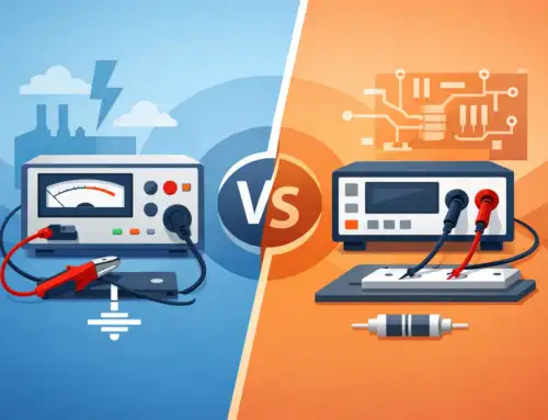
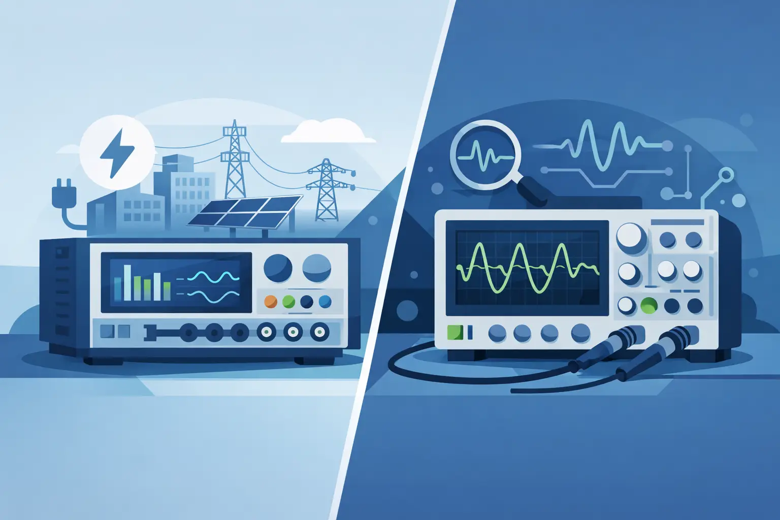
An oscilloscope is usually the appropriate first choice for bench diagnosis, prototype bring-up, visual waveform inspection, and flexible one-off measurements. A digitizer is usually the stronger choice when data capture must be programmable, synchronized, repeated at scale, or incorporated into a larger test system.
There is also no requirement to standardize on one approach for every phase of a program. A development team may use an oscilloscope to understand failure mechanisms and a digitizer-based system to execute the final qualification or production test. The most effective measurement architecture is the one that preserves signal fidelity while giving the engineering team a repeatable path from observation to evidence.