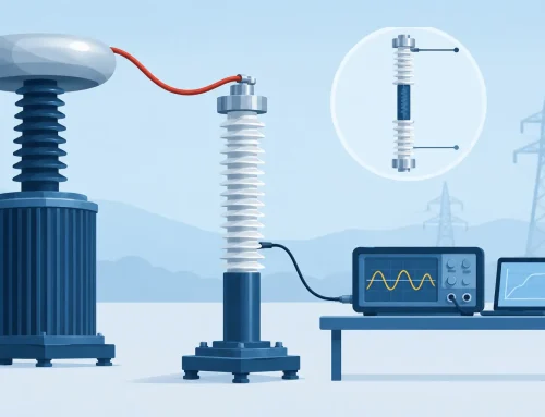
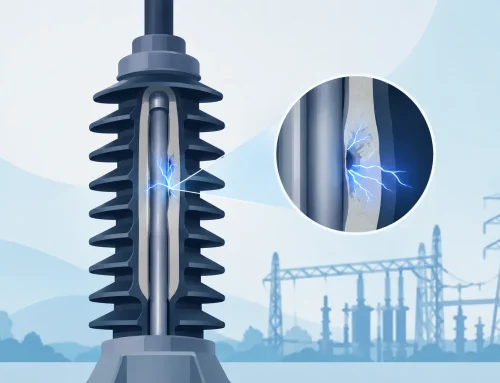
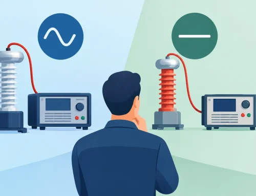
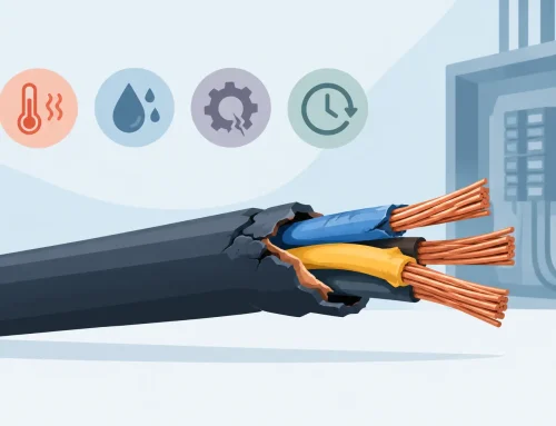
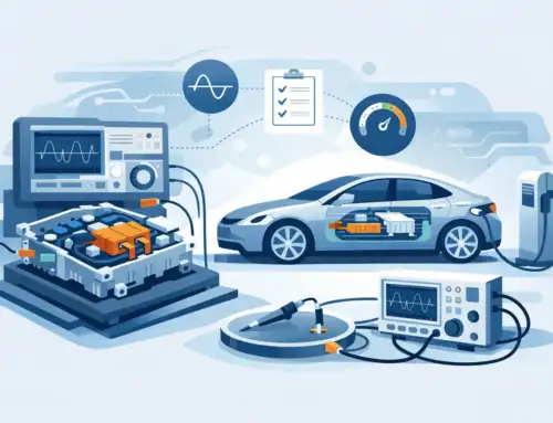
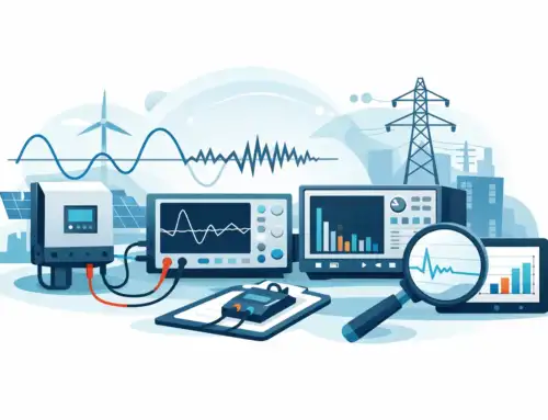
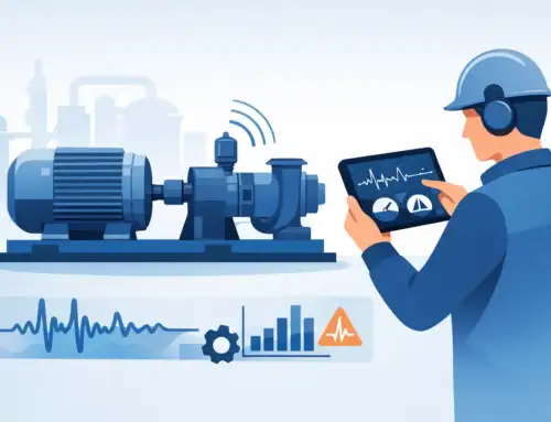
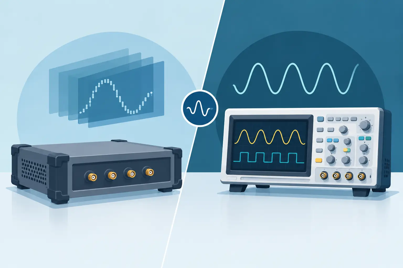
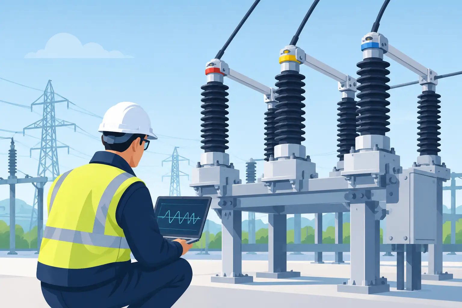
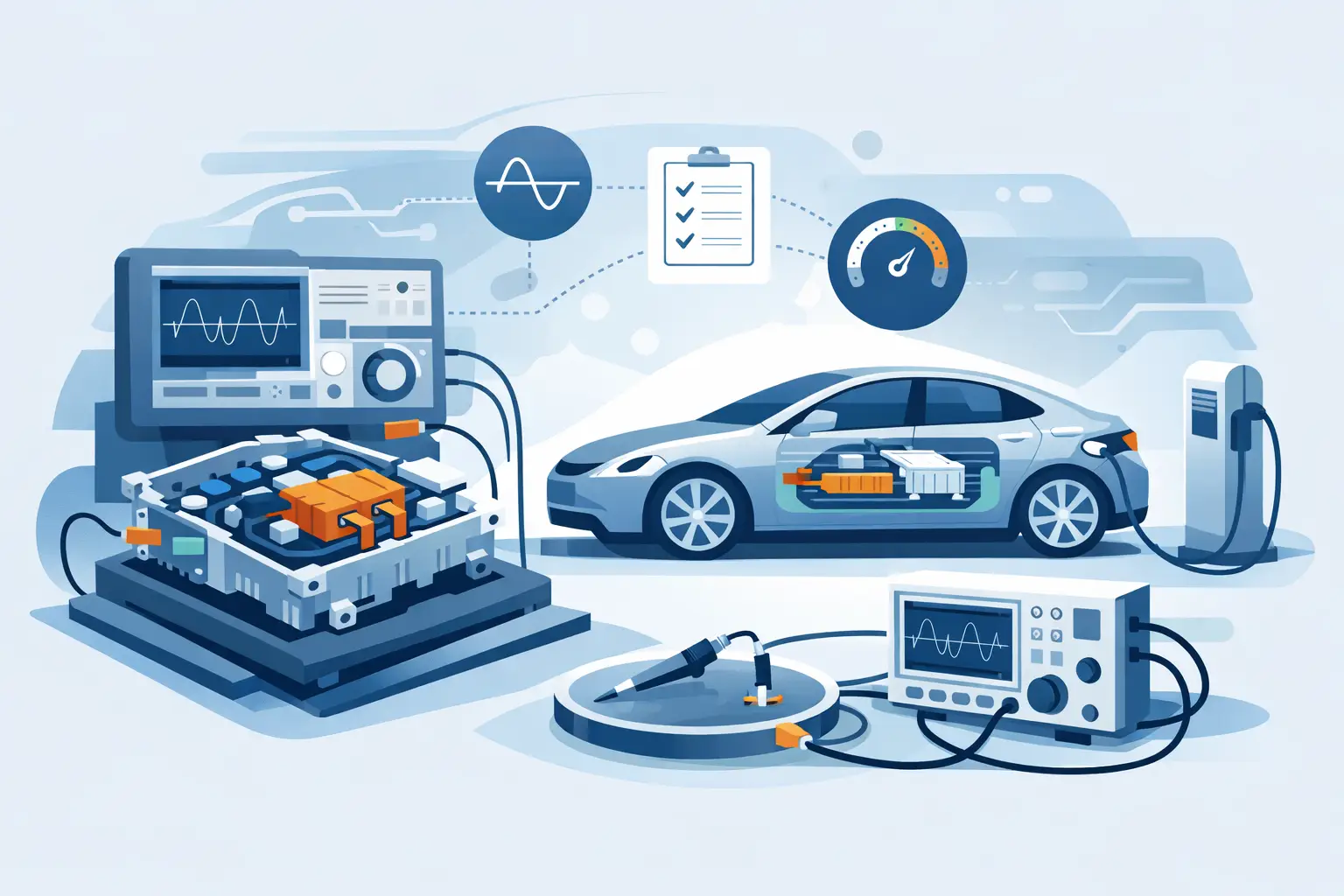
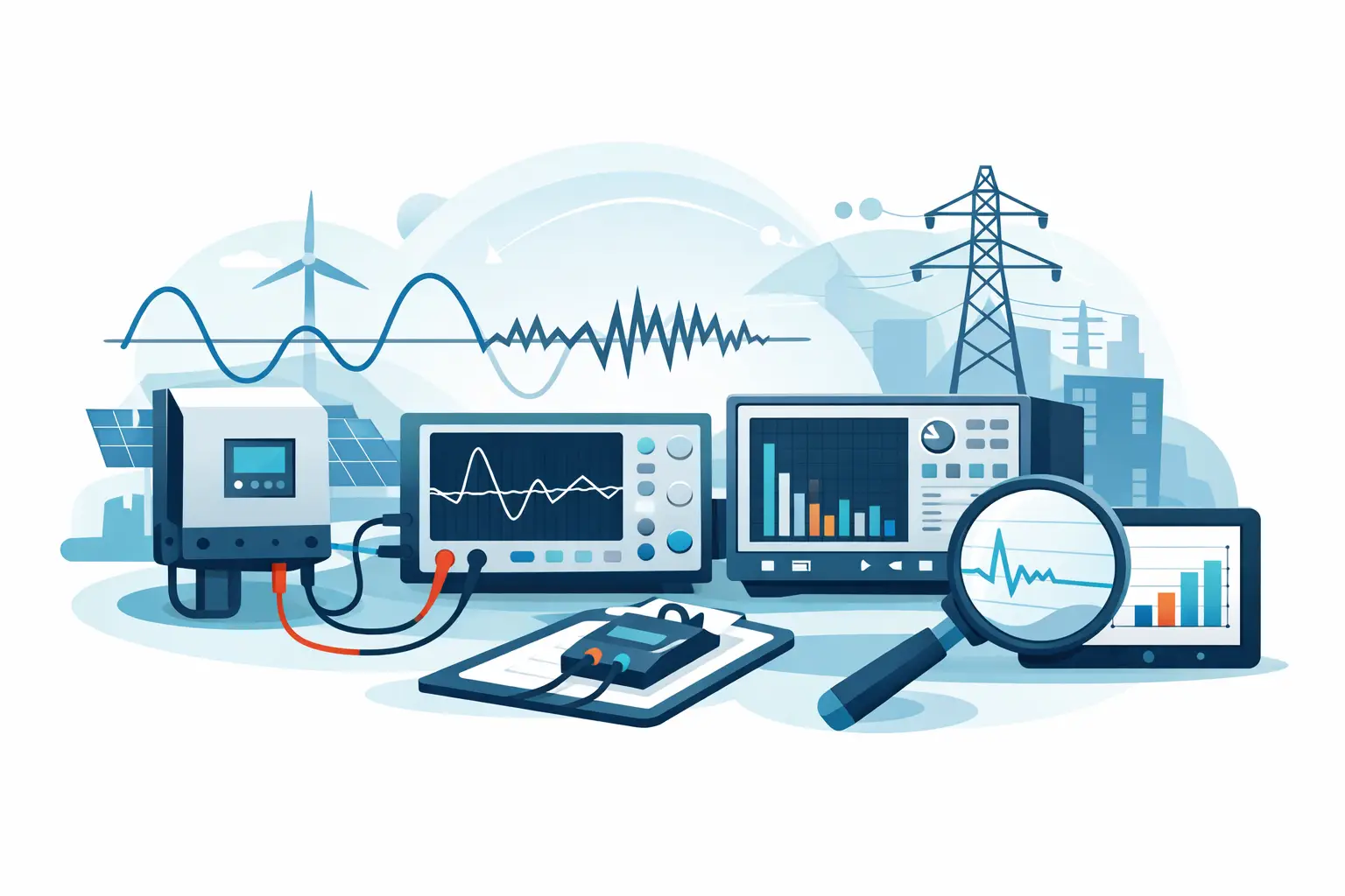
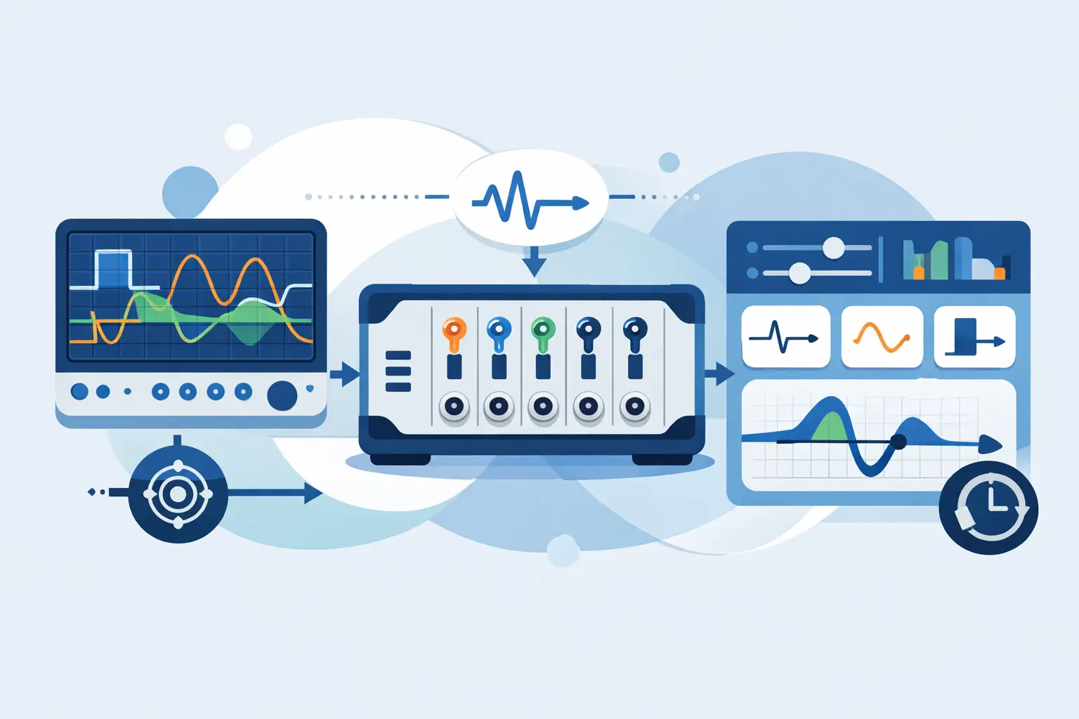
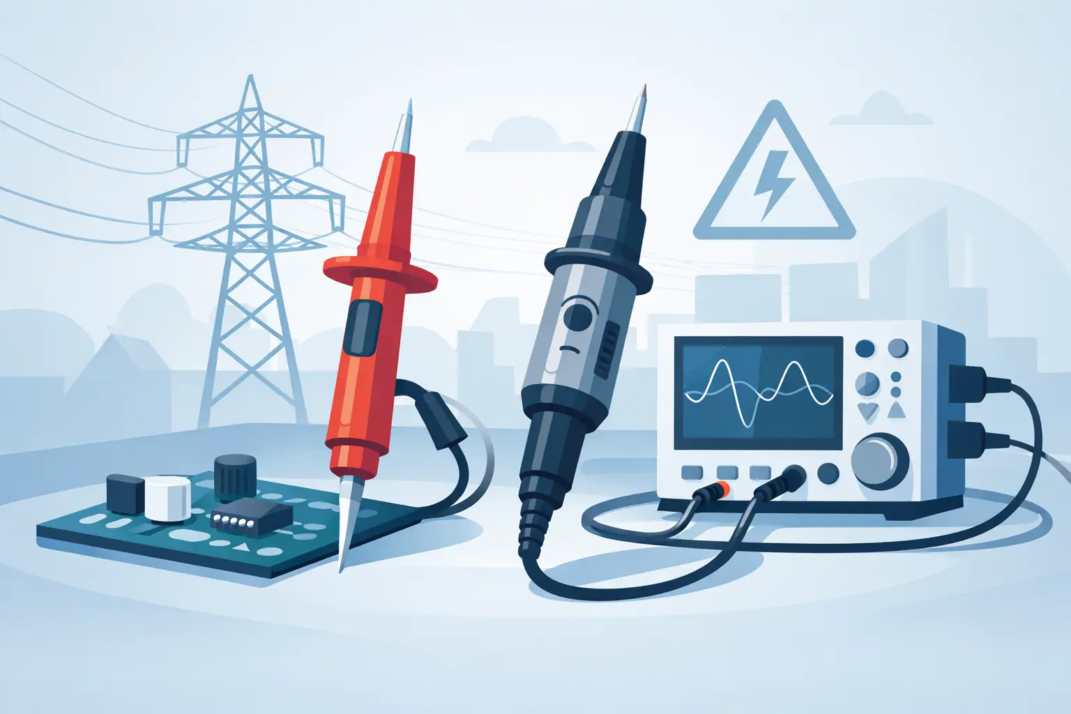
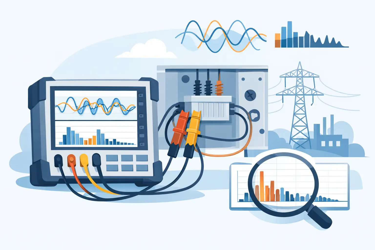
A transient that occurs once every few thousand cycles can still determine whether a power converter passes validation, a vehicle controller resets, or an insulation system experiences unexpected stress. To configure transient voltage capture effectively, the acquisition system must be designed around the event itself: its expected amplitude, rise time, repetition rate, source location, and safety category. A fast instrument alone cannot compensate for an unsuitable probe, an incorrect trigger threshold, or insufficient pre-trigger memory.
For engineering teams investigating switching overshoot, line disturbances, load-dump events, relay arcing, or intermittent faults, the objective is not simply to record a waveform. It is to produce a time-correlated, amplitude-accurate record that can support root-cause analysis, design decisions, and compliance documentation.
Start With the Transient You Need to See
Transient capture settings should begin with a test definition rather than default instrument parameters. Identify the nominal voltage, maximum credible excursion, expected polarity, and the fastest edge that may occur. Also define whether the event is periodic, command-related, random, or dependent on a changing load condition.
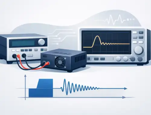
A switching-node overshoot in a wide-bandgap inverter may last tens of nanoseconds and repeat at the PWM frequency. A utility-line disturbance or automotive load transient may persist for milliseconds but occur infrequently. These cases require different combinations of sample rate, record length, trigger strategy, and input range.
Amplitude range deserves particular attention. Set the digitizer or oscilloscope input range high enough that the largest expected event does not clip, while keeping it low enough to preserve useful vertical resolution for the nominal waveform and smaller anomalies. If the system provides programmable gain, confirm that gain changes will not occur during the acquisition interval. A clipped transient can establish that an event occurred, but it cannot provide a defensible peak-voltage measurement.
Select the Measurement Path Before Configuring Capture
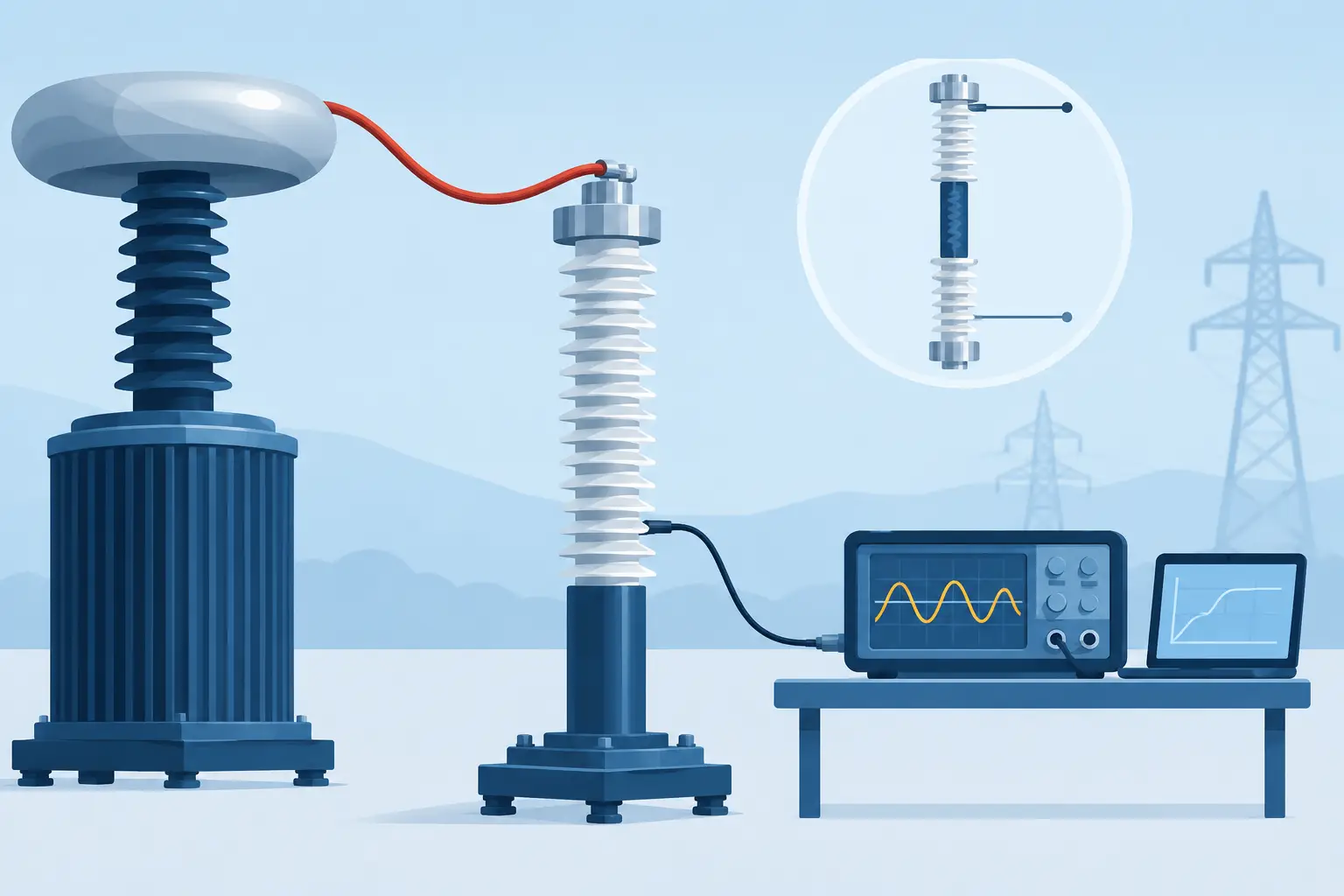
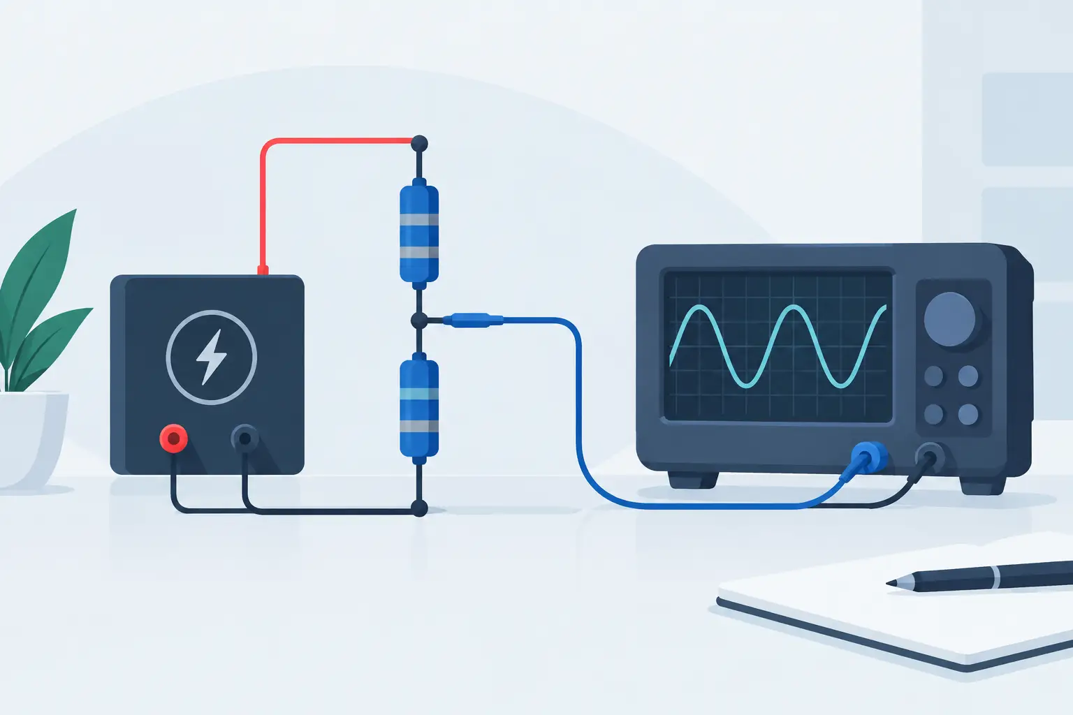
The probe, attenuator, cabling, and instrument input form a measurement system. Their combined bandwidth, voltage rating, common-mode capability, and loading characteristics determine what reaches the digitizer.
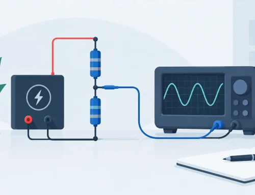
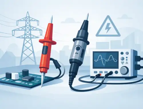
For grounded low-voltage circuits, a properly rated passive or active probe may be appropriate. For high-side switching measurements, floating systems, or high common-mode environments, use an appropriately rated differential probe or isolated measurement approach. The probe’s differential voltage rating is only one part of the decision. Its common-mode rating, bandwidth under the actual attenuation setting, and specified transient immunity must also cover the application.
Avoid long ground leads on conventional probes when measuring fast edges. Their inductance can create ringing that appears to be part of the circuit under test. Use the shortest practical ground connection or a probe accessory designed for low-inductance connections. Likewise, a long coaxial run can introduce reflections if source and termination impedances are not considered. A 50-ohm measurement path may improve high-frequency signal integrity, but it also loads the source substantially. It is appropriate only when the circuit can drive that load or when a suitable buffer or attenuator is used.
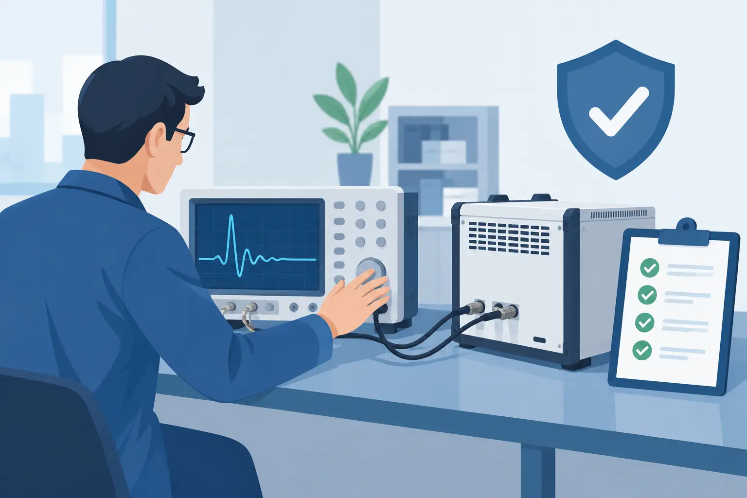
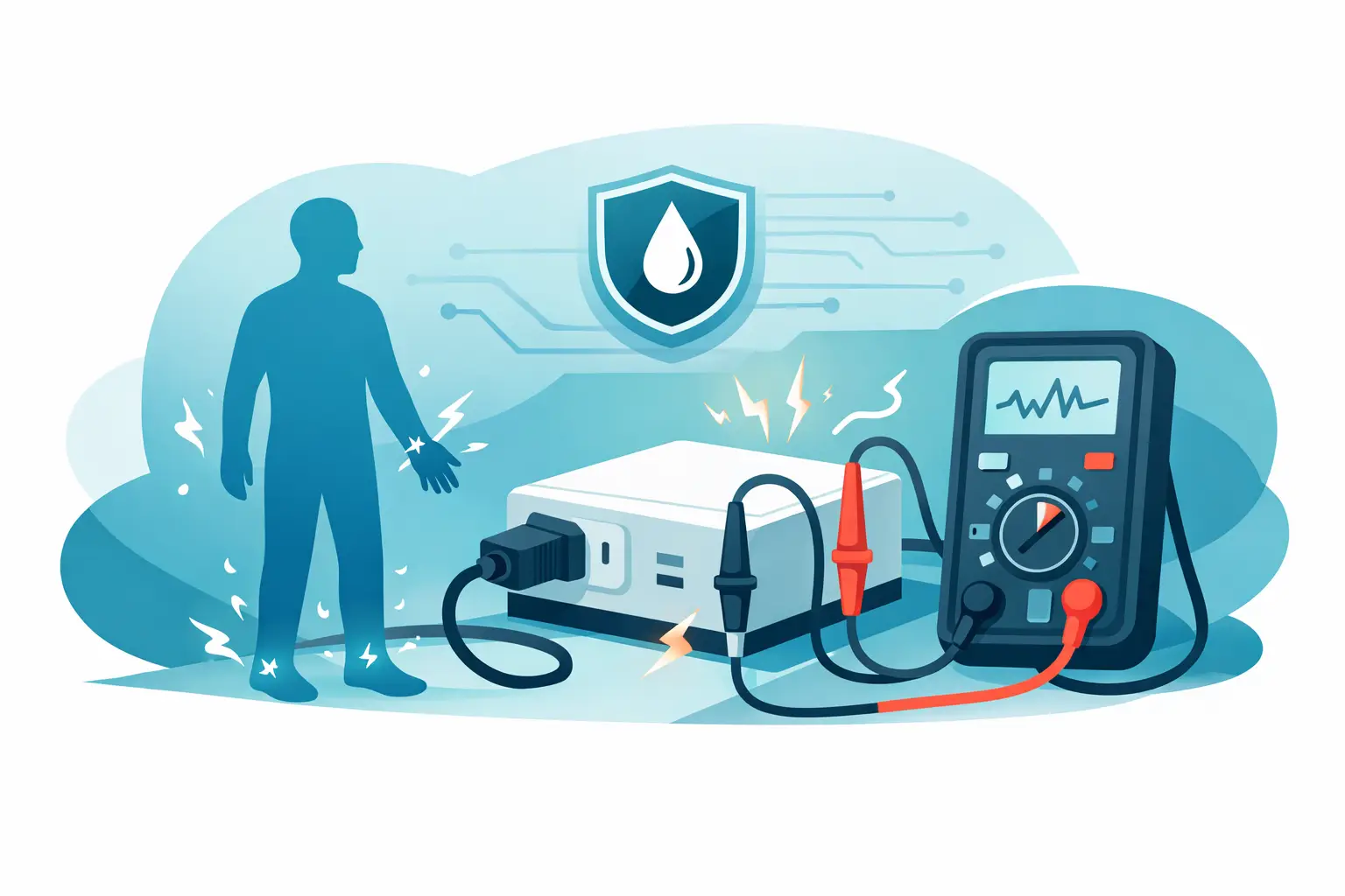
Before connecting to energized equipment, verify the installation against applicable safety procedures and the ratings of every component in the signal path. This includes leads, connectors, feedthroughs, probes, attenuators, and the instrument input. High-energy transients demand more than adequate peak-voltage ratings; fault energy and installation category matter as well.
How to Configure Transient Voltage Capture Settings
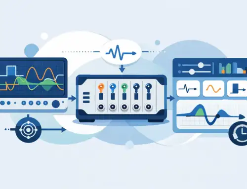
The primary capture parameters are sample rate, acquisition bandwidth, record length, pre-trigger percentage, trigger mode, and trigger threshold. They are interdependent, so changing one often requires reviewing the others.
Set sample rate from edge speed and bandwidth
Sample rate should be selected from the fastest waveform content that must be measured, not merely from the fundamental frequency of the circuit. A useful starting point is to acquire at several times the required measurement bandwidth. Higher oversampling can improve waveform definition and timing analysis, but it consumes memory more quickly and may reduce the available capture duration at a fixed record size.
The instrument’s analog bandwidth must also be sufficient. Increasing sample rate cannot recover frequency content removed by a limited-bandwidth front end or probe. Conversely, using excessive bandwidth in a noisy environment can make trigger stability and amplitude measurements worse. Apply bandwidth limiting only when it is consistent with the highest-frequency content relevant to the test objective.
For very fast events, confirm the sample rate applies to the number of active channels in the intended configuration. Some systems share converter resources between channels, reducing the per-channel rate when additional inputs are enabled.
Size the record for context, not just the spike
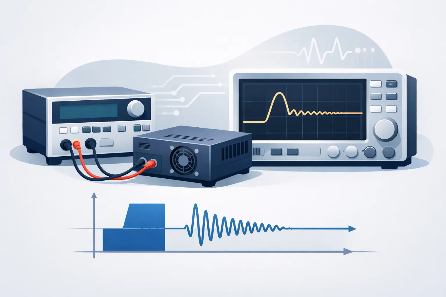
A transient record should include enough time before and after the event to explain it. Pre-trigger data can reveal the command transition, load condition, or voltage trend that preceded the excursion. Post-trigger data shows damping, recovery time, repeated ringing, or the effect of protection circuitry.
If an event is expected to occur within a known command sequence, use a record long enough to cover the relevant sequence rather than capturing only the peak. If the event is random, a shorter record with repeated acquisitions may be more efficient. The right trade-off depends on whether the investigation needs broad operational context or maximum resolution around a short-lived anomaly.
Choose a trigger that represents the failure mechanism
A rising- or falling-edge trigger is often sufficient for predictable overshoot. Set the threshold above normal noise and below the minimum event amplitude that must be captured. Triggering too close to the baseline causes false captures; setting the threshold too high misses smaller but still significant disturbances.
For bipolar events, window, pulse-width, or runt triggers can be more selective than a simple edge trigger. For power-quality investigations, trigger on an external command, current probe, digital control signal, or another correlated channel when voltage alone is not a reliable indicator. An external trigger can be especially valuable when the voltage transient is too brief or irregular to establish a stable threshold.
Use trigger holdoff when repetitive ringing creates multiple triggers from one physical event. Holdoff should exceed the ringing interval but remain shorter than the expected time between distinct events. This prevents a high acquisition count from being mistaken for a high fault rate.
Preserve Timing and Amplitude Integrity
When several channels are used to compare gate drive, current, DC bus voltage, and output voltage, synchronization is part of the measurement requirement. Confirm channel-to-channel skew, probe delay, and trigger timing uncertainty. A small timing error can change the apparent relationship between current commutation and voltage overshoot, leading to an incorrect diagnosis.
Compensate or document probe delays when timing relationships are measured in nanoseconds or low microseconds. Perform a functional check with a known fast-edge source before testing the production assembly. This check can reveal inverted polarity, unexpected attenuation, probe saturation, cable-induced reflections, and trigger alignment errors before valuable test time is spent on suspect data.
For high-voltage measurements, verify attenuation ratio and calibration status. A digitizer may provide excellent intrinsic accuracy, but the complete result is governed by the weakest component in the measurement chain. Calibration traceability, stated uncertainty, environmental conditions, and probe derating should be recorded when measurements support qualification or compliance evidence.
Validate the Setup With Controlled Events
A capture configuration is not complete when the instrument displays a waveform. It is complete when the team can show that the system reliably captures representative events without clipping, false triggers, or material distortion.
Begin with a controlled stimulus if one is available, such as a known switching condition, pulse generator, surge source, or commanded load transition. Capture enough repetitions to assess trigger reliability and waveform consistency. If peak amplitude or timing varies, determine whether the variation is in the device under test or in the measurement system.
Review each acquisition for input overload indicators, trigger position, baseline noise, and unexpected ringing. Compare the observed waveform with expected circuit behavior and, where practical, confirm it with an alternate probe or measurement location. Agreement between two independently configured paths is often more persuasive than a single visually convincing trace.
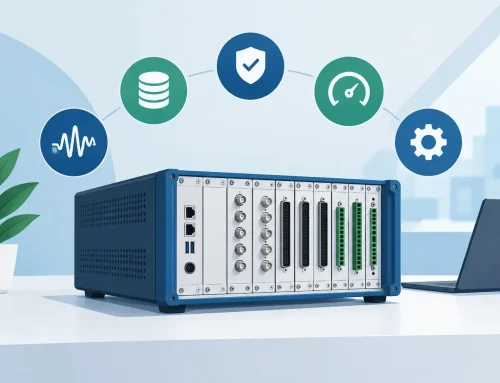
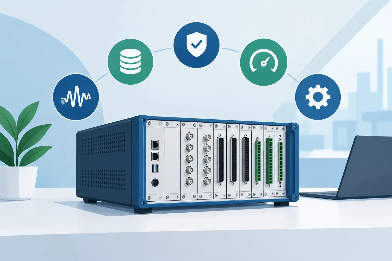
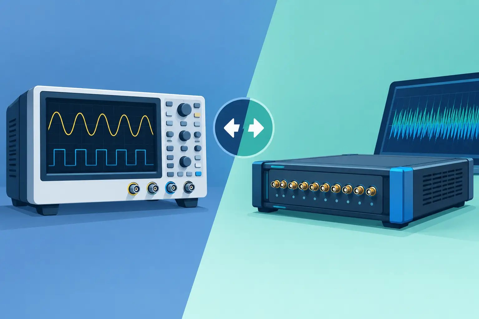
Save the raw waveform, configuration file, probe details, sample rate, bandwidth setting, input range, trigger parameters, and test conditions together. This preserves the measurement context for later design reviews, failure analysis, or audit requirements. High-speed digitizer platforms and acquisition software can support repeatable capture sequences, but repeatability still depends on disciplined configuration control.
Common Capture Failures and Their Causes
When a transient is missing, the trigger is commonly the first issue, but it is not the only one. The event may be faster than the measurement path, outside the configured record window, attenuated by an unsuitable probe, or hidden by bandwidth filtering. When a waveform looks unusually noisy, investigate probe grounding, common-mode limits, cable routing, termination, and electromagnetic coupling before attributing the behavior to the circuit.
A frequent error is optimizing every parameter for maximum speed. Maximum bandwidth, maximum sample rate, and the shortest record may capture a sharp edge while omitting the operating condition that explains it. Another is configuring for broad context with so much range and memory depth that the peak is poorly resolved. The appropriate settings depend on the engineering question, not on the highest available specification.
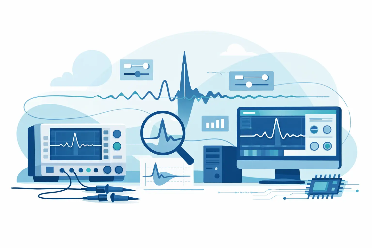
The most useful transient record is one that connects the event to a cause: the switching command that preceded it, the current change that accompanied it, the protection response that followed it, and the verified limits of the measurement system. Configure the capture around that chain of evidence, and the waveform becomes a reliable engineering result rather than an isolated screen image.