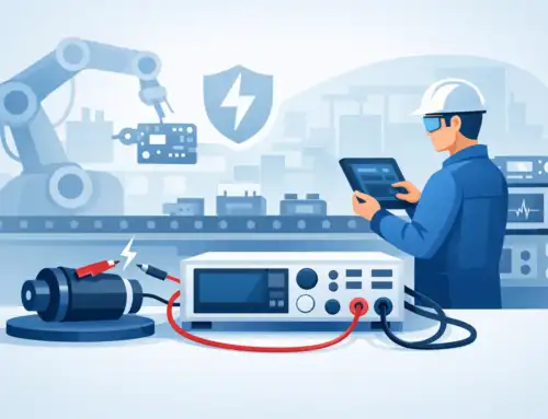
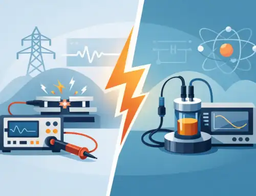
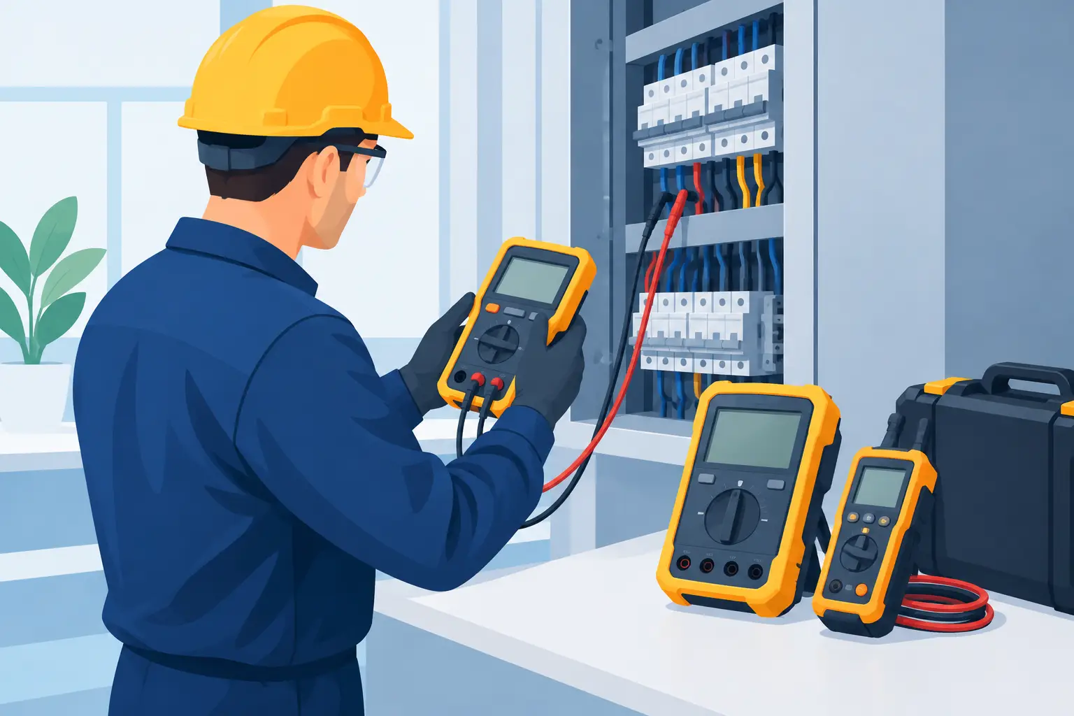
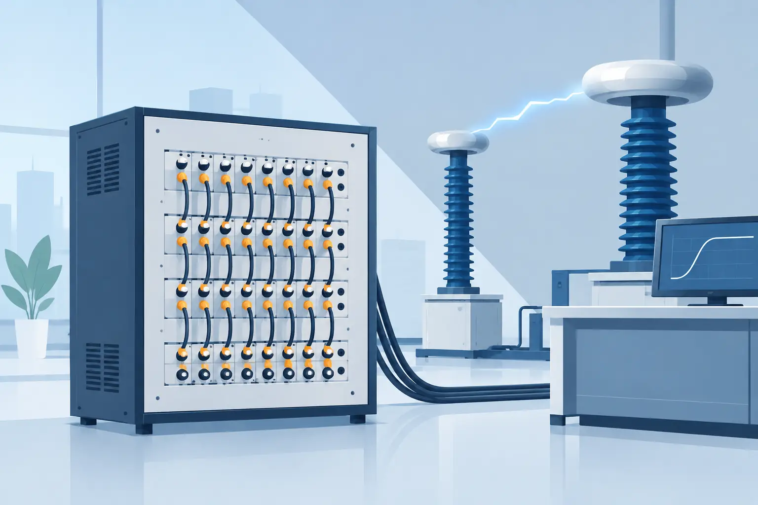
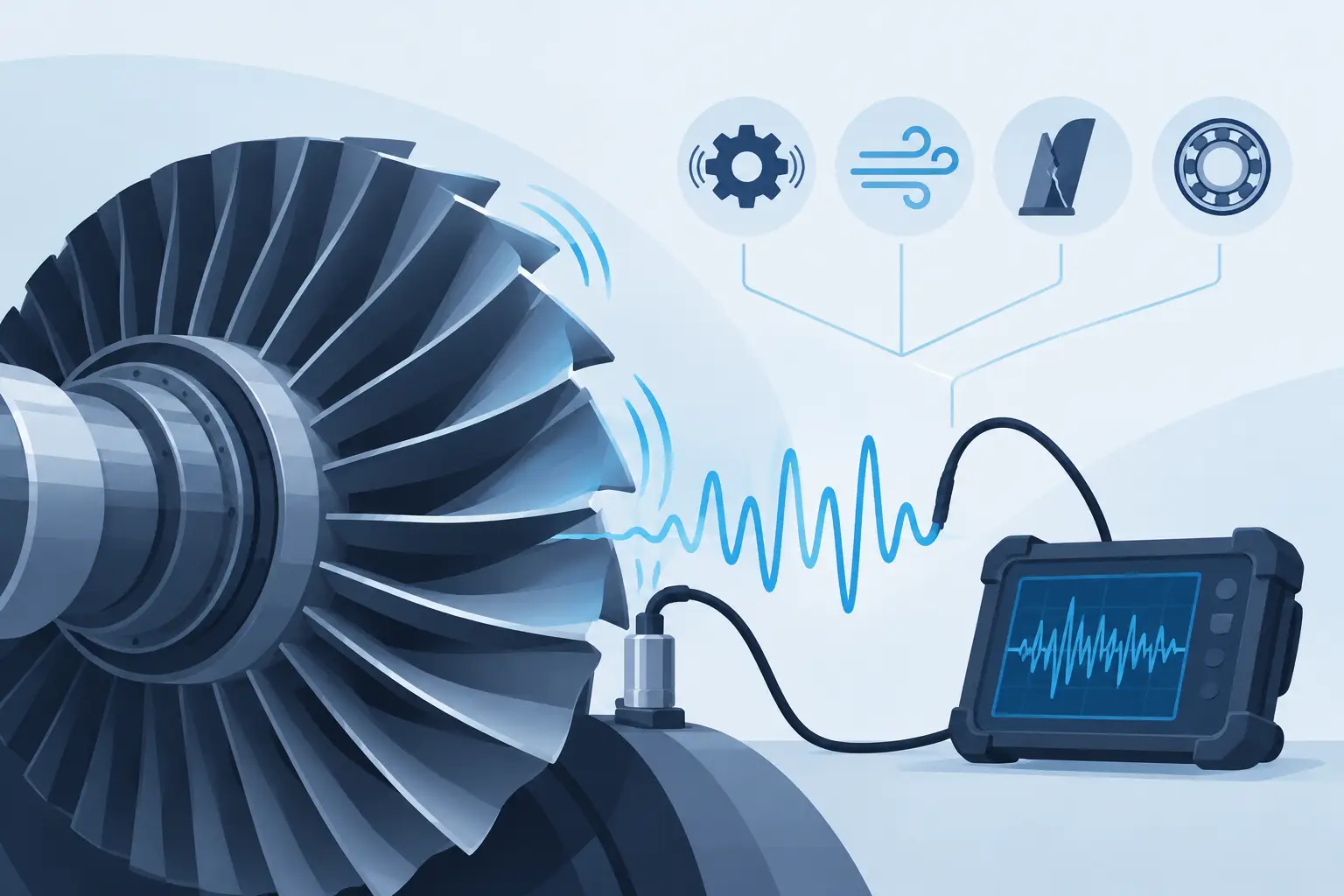
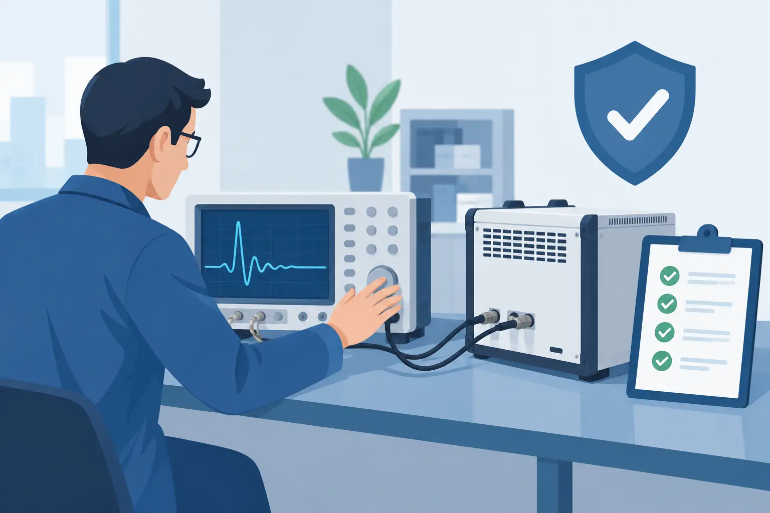
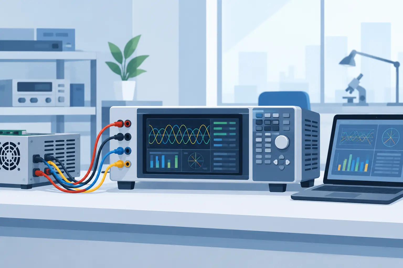
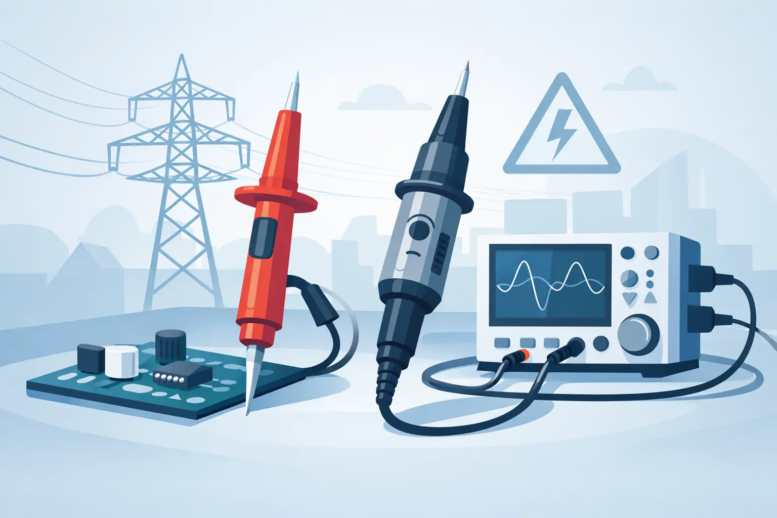
A divider that survives the applied voltage but distorts the measured waveform is not a successful measurement solution. In high-energy, high-frequency, or compliance-critical test environments, a high voltage divider selection guide must address more than nominal voltage and ratio. The divider becomes part of the measurement system, affecting uncertainty, transient fidelity, operator safety, and the validity of the final test record.
For aerospace power hardware, EV inverters, insulation systems, pulsed supplies, and laboratory R&D, the right choice depends on the voltage waveform, source impedance, required bandwidth, instrument input, environmental conditions, and the applicable safety standard. A resistor value alone cannot resolve those requirements.
Start With the Measurement Objective
Define what the test must prove before selecting a divider. A DC withstand test may require stable, low-drift voltage measurement over minutes or hours. A switching transient investigation may require nanosecond-scale response and tightly controlled frequency behavior. An impulse or surge test may require a divider that can tolerate steep-front waveforms without flashover, excessive overshoot, or internal damage.
The voltage range should include normal operating voltage, foreseeable overvoltage, and the margin required by the test method. Selecting a divider at its published maximum working voltage can be reasonable only when the installation, duty cycle, waveform, and environmental conditions match its rating basis. Repetitive pulses, elevated temperature, altitude, humidity, contamination, and enclosure geometry can all reduce practical margin.
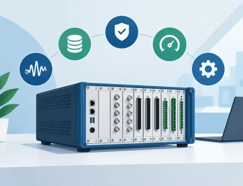
Also establish the required measurement uncertainty at the point of use. A divider specified at 0.1% ratio accuracy may not deliver 0.1% total system uncertainty once the digitizer or voltmeter accuracy, calibration uncertainty, temperature coefficient, loading effects, and frequency response are included. Requirements should be allocated across the complete measurement chain.
Select the Divider Technology for the Waveform
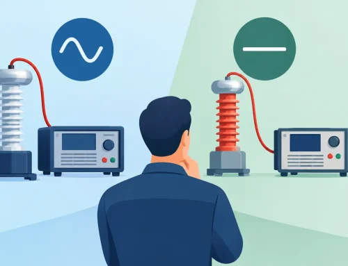
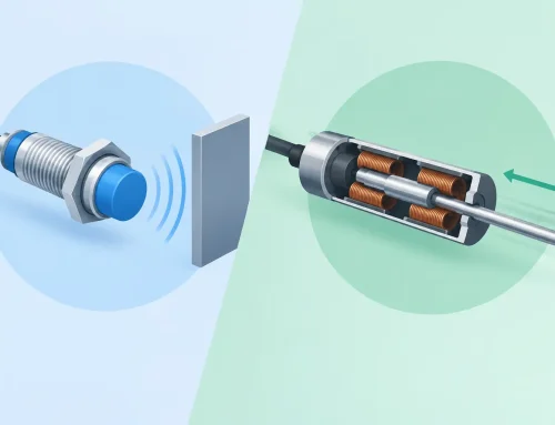
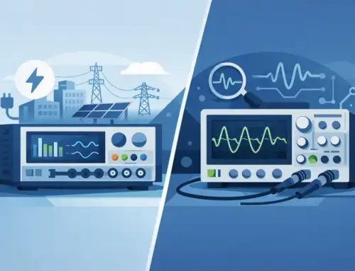
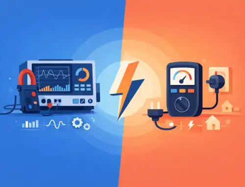
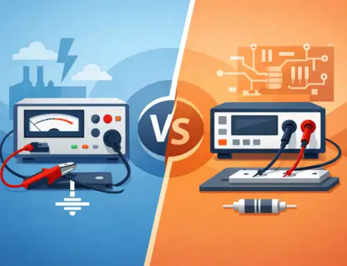
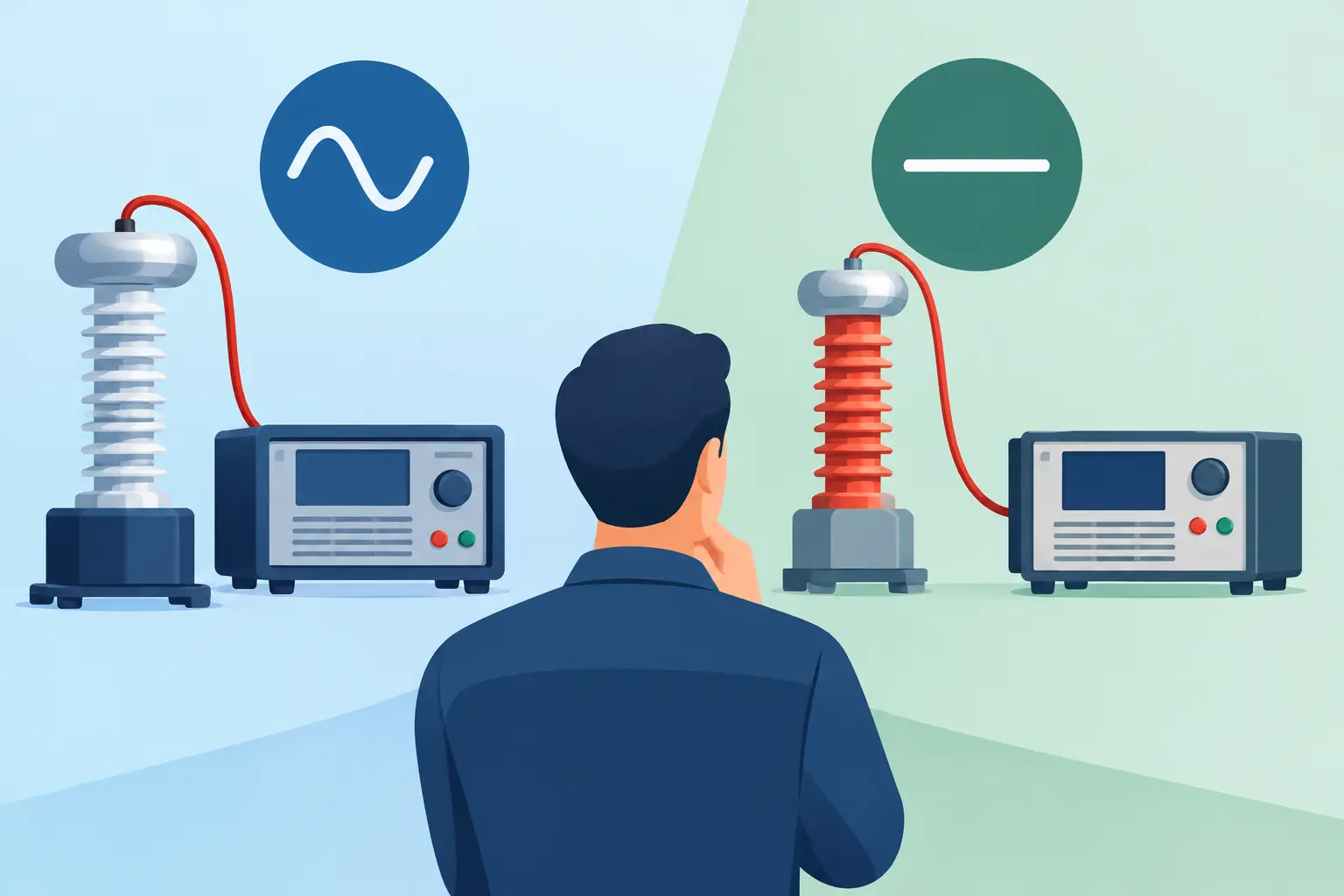
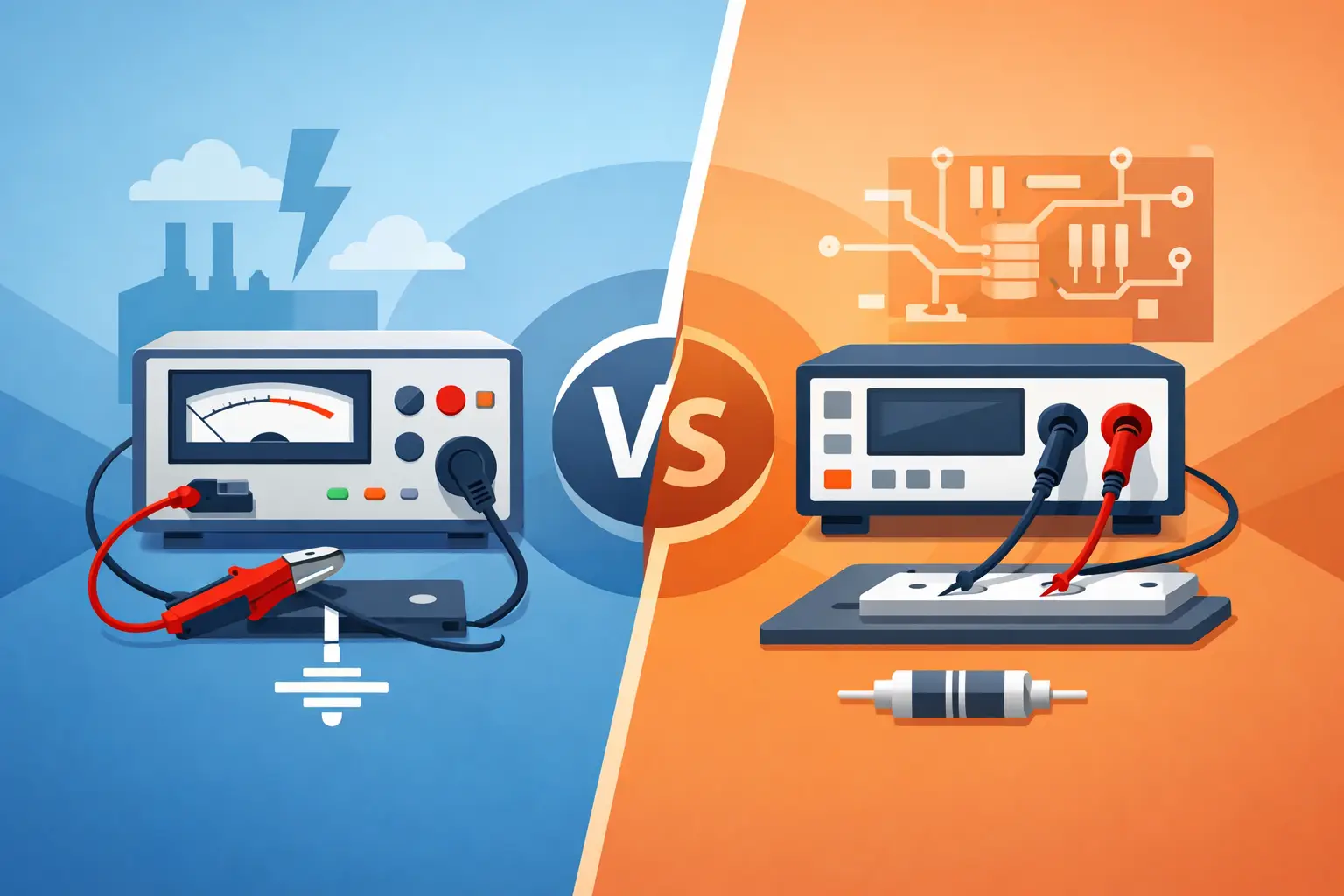
High-voltage dividers are generally resistive, capacitive, or compensated resistive-capacitive designs. Each approach has useful operating territory and meaningful limitations.
Resistive Dividers
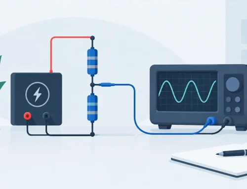
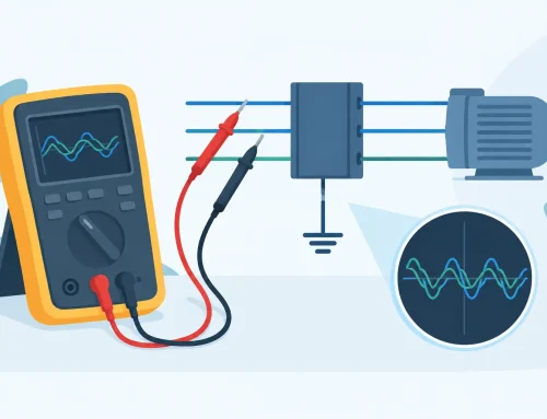
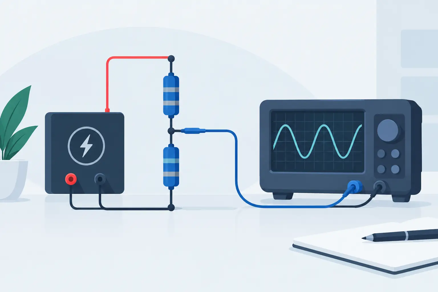
A resistive divider is often the preferred approach for DC and low-frequency AC measurements because it provides a direct relationship between input voltage and output voltage. With appropriately selected high-value resistor networks, insulation design, and thermal management, resistive dividers can support precise measurements over a broad voltage range.
The trade-off is power dissipation. Divider current creates heat, and resistor temperature rise changes resistance values and ratio accuracy. At high voltage, even a modest divider current can produce substantial power. For example, a 100 kV measurement across a 1 Gohm divider draws 100 microamps and dissipates 10 W. That heat must be distributed safely and predictably through the resistor chain.
Resistive dividers also have parasitic capacitance. At higher frequencies, the distributed capacitance of the resistor network and output connections can alter the response, creating attenuation error, phase shift, or waveform distortion.
Capacitive Dividers
Capacitive dividers are well suited to AC, impulse, and fast transient measurements. Their low power loss is especially valuable at high voltages and frequencies where a resistive approach would dissipate excessive energy. In a basic capacitive divider, the output depends on the ratio of capacitances rather than resistance.
They are not usually the first choice for DC measurements because an ideal capacitor blocks DC after charging. Leakage paths, dielectric absorption, and input resistance can influence low-frequency behavior. Capacitive divider performance also depends strongly on the instrument input capacitance and the physical layout of the measurement circuit.
Compensated Dividers
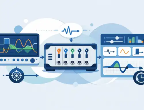
A compensated divider combines resistive and capacitive elements to maintain a consistent division ratio across a defined frequency range. This is often the appropriate approach when both low-frequency accuracy and fast transient response matter, such as power electronics characterization, pulse testing, and switching waveform capture.
Compensation must be considered as a system property, not just a divider feature. Cable length, probe connections, digitizer input impedance, input capacitance, and grounding arrangement can shift the response. A divider that is correctly compensated with one instrument configuration may require verification when connected to another.
Match Ratio, Output Level, and Instrument Input
The division ratio must keep the instrument input within its rated voltage range under normal and fault conditions. It should also produce sufficient output amplitude to use the available resolution and noise performance of the voltmeter, digitizer, or data acquisition system.
An excessively high ratio protects the input but can leave only a small signal at the measuring instrument, reducing effective resolution. An unnecessarily low ratio may overdrive the instrument during overshoot or abnormal operation. The practical target is an output signal that uses a meaningful portion of the input range while retaining headroom for expected transients.
Input impedance matters just as much. A divider calibrated into a 10 megohm input may show a different ratio when connected to a 1 megohm instrument. Input capacitance becomes increasingly significant as bandwidth increases. Confirm the specified load conditions for the divider and compare them with the actual instrument and cable configuration.
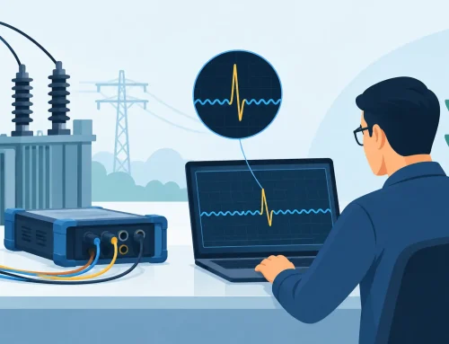
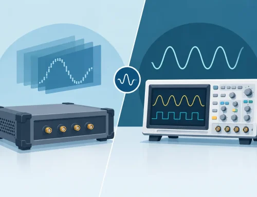
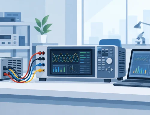
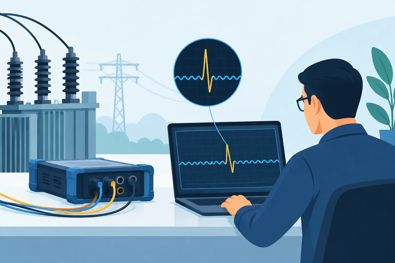
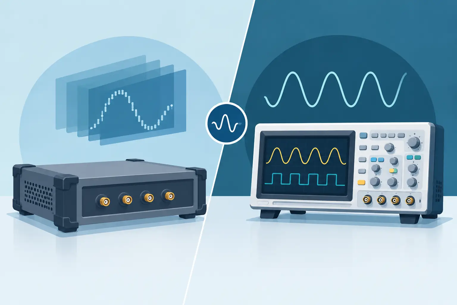
For digitized measurements, consider the required sample rate and vertical resolution alongside divider bandwidth. A fast divider connected to an undersampled digitizer does not produce a valid representation of a fast event. Conversely, a high-bandwidth acquisition path can reveal ringing caused by test-fixture inductance rather than the device under test. Measurement planning should account for both possibilities.
Evaluate Bandwidth and Transient Performance
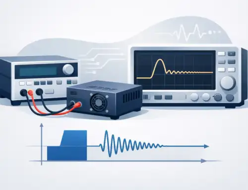
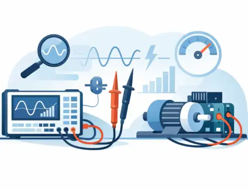
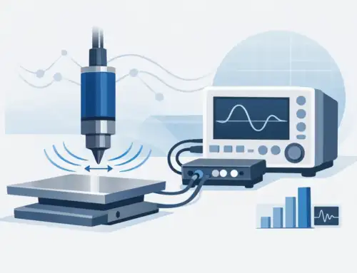
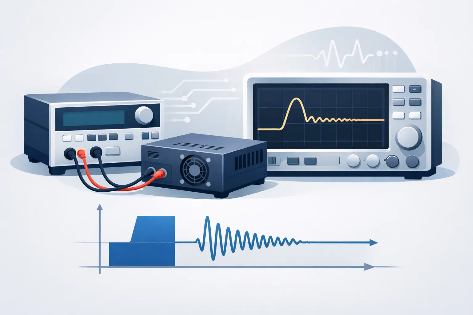
Bandwidth specifications are useful, but they do not fully describe transient fidelity. A divider can have an acceptable nominal bandwidth while still exhibiting step-response overshoot, ringing, slow settling, or pulse droop that compromises a specific test.
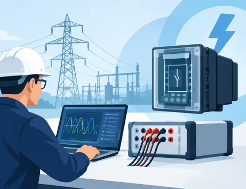
For switching devices and pulse power applications, review the rise time, settling time, amplitude flatness, phase response, and step response. The physical arrangement matters. Long ground leads, unshielded output cables, and uncontrolled return paths add inductance and susceptibility to interference. In high-voltage pulsed work, a carefully engineered divider can be undermined by poor interconnection practice.
The source itself also influences the result. A divider connected across a low-impedance impulse source behaves differently from one connected to a high-impedance capacitive supply. Where waveform accuracy is critical, validate the complete setup using a known source or comparison method under conditions that resemble the actual test.
Verify Insulation Coordination and Safety Requirements
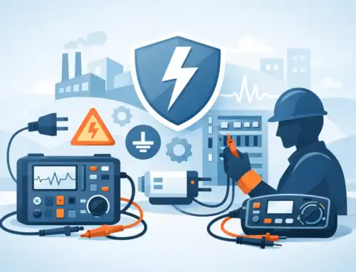
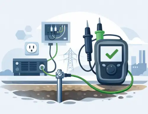
Electrical ratings must be supported by physical insulation design. Review creepage distance, clearance distance, dielectric materials, connector ratings, shielding, and enclosure requirements. The appropriate distances depend on voltage, pollution degree, altitude, material group, installation category, and whether the equipment is intended for laboratory or industrial use.
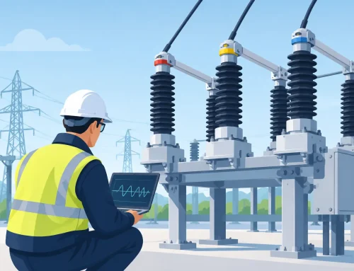
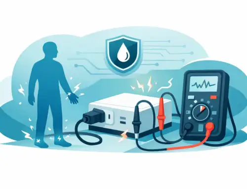
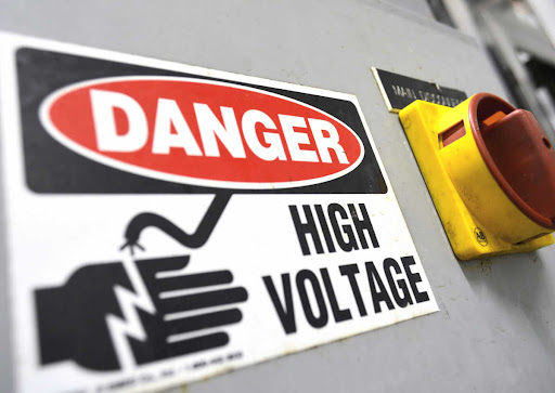
A divider used in a guarded test enclosure has different exposure risks than one used on an open bench. Access to energized conductors, stored energy, discharge paths, grounding provisions, and interlock integration should be addressed at the system level. The divider should not introduce a hazardous accessible voltage at its low-voltage output or measurement connector.
For regulated equipment, identify the standards governing the application early. Depending on the system, this may include IEC 61010 measurement safety requirements, IEC 60664 insulation coordination principles, IEC 60060 high-voltage test techniques, or industry-specific procedures. Compliance claims should be evaluated against the actual intended installation and use case, not assumed from a component rating.
Consider Partial Discharge, Environmental Effects, and Duty Cycle
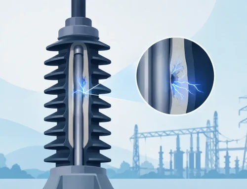
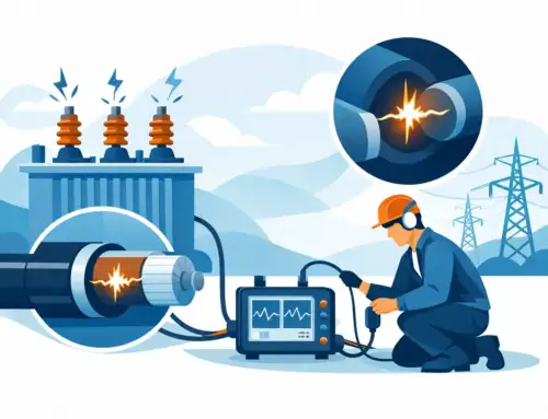
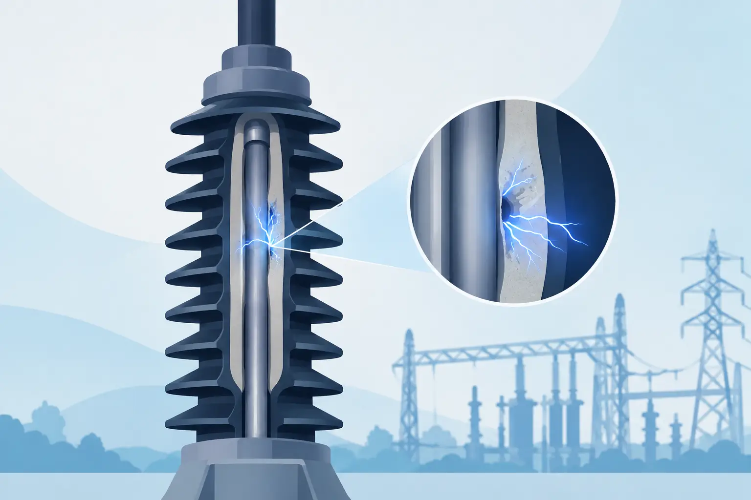
Partial discharge performance is especially relevant in high-voltage AC, impulse, and insulation-validation environments. Internal voids, sharp conductor geometry, contaminated surfaces, and inadequate field grading can initiate discharge well below catastrophic breakdown. This can introduce measurement noise, accelerate insulation degradation, and compromise repeatability.
Environmental conditions deserve equal attention. Humidity and surface contamination can create leakage currents that alter ratio accuracy. Temperature changes affect resistance and capacitance. At altitude, reduced air density can lower external insulation withstand capability. For production systems, evaluate the expected duty cycle as well as single-event capability. A divider rated for occasional laboratory measurements may not be suitable for continuous automated testing.
Require Calibration That Supports Measurement Integrity
Calibration should verify the ratio under relevant voltage, frequency, and loading conditions. A low-voltage resistance check can confirm part of a resistive network, but it may not reveal high-voltage leakage, field-related effects, or frequency-dependent errors. For precision applications, calibration records should identify the divider, ratio, uncertainty, traceability, environmental conditions, and instrument configuration.
Establish a recalibration interval based on use intensity, required uncertainty, environmental exposure, and quality-system requirements. A divider that experiences repeated impulses, thermal cycling, transport, or high-humidity storage may warrant more frequent verification. Before critical tests, inspect the assembly for damaged insulation, contamination, loose connections, and changes in cable routing.
The best divider selection is the one that produces defensible data in the real test configuration, not merely favorable specifications on a data sheet. Define the waveform, uncertainty, load, safety boundary, and operating environment first. That discipline gives engineers a measurement path they can validate, repeat, and rely on when the result matters.