A high-voltage insulation system can pass a conventional withstand test and still contain a defect that is actively degrading it. That defect may produce only brief, localized electrical events, but repeated activity can become a reliable precursor to insulation failure. So, what is partial discharge? It is a localized electrical discharge that bridges only part of an insulating medium between conductors, without completely bridging the insulation system.
What Is Partial Discharge?
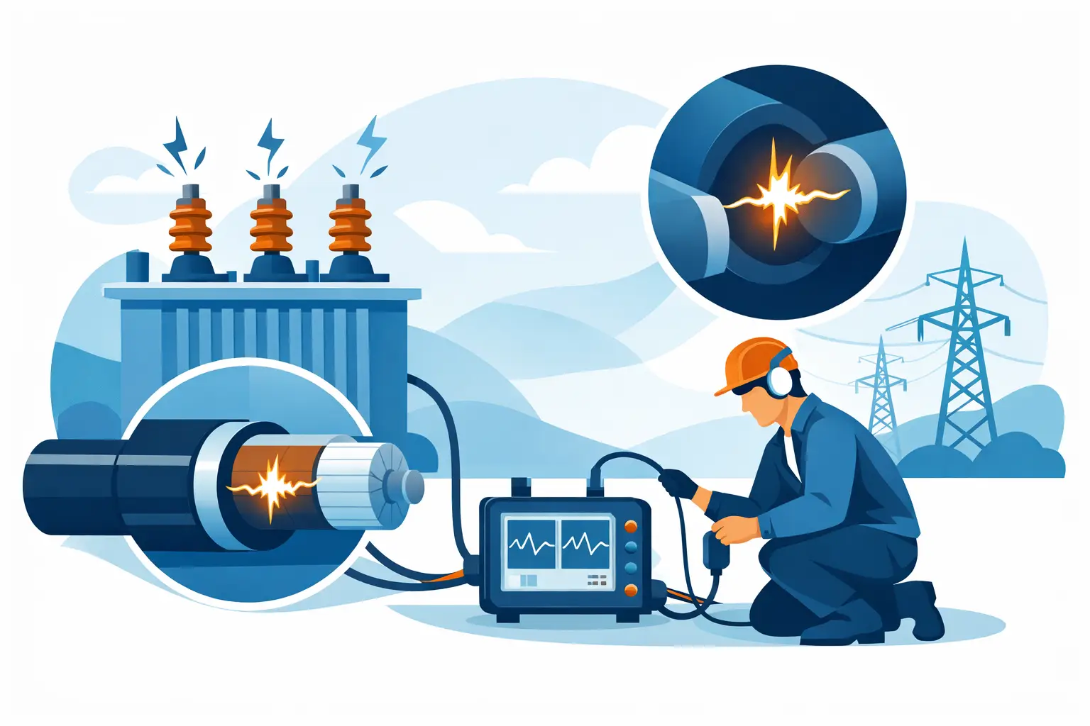
Partial discharge, commonly abbreviated PD, occurs when the electric field at a localized point exceeds the dielectric strength of the surrounding material or medium. The discharge is confined to a small region, such as an internal void, a delaminated interface, a sharp conductor edge, or a contaminated surface. Unlike a complete dielectric breakdown, it does not create a sustained conductive path from one electrode to another.
That distinction matters in test and reliability work. A component may remain functional while PD is present, yet each discharge can damage insulation through chemical attack, heat, ion bombardment, ultraviolet radiation, and localized mechanical stress. Over time, those effects can enlarge a void, erode a surface, form electrical trees, and reduce the margin between normal operation and catastrophic failure.
PD is most relevant in medium- and high-voltage equipment, including motors, generators, transformers, cable systems, switchgear, capacitors, power modules, aerospace power equipment, and EV traction systems. It can also be a concern in compact electronic assemblies where high electric-field stress is concentrated across small clearances or insulation layers.
Where Partial Discharge Starts
The electrical field is rarely uniform in a practical assembly. Manufacturing variation, material interfaces, geometry, contamination, and aging all create locations where the local field is substantially higher than the average field predicted from terminal voltage alone.
Internal discharge
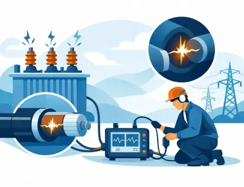
Internal PD occurs within gas-filled voids, cracks, inclusions, or separations inside a solid or liquid insulation system. A void has a lower dielectric constant than the surrounding insulation, which can increase the electric-field stress across the void. When ionization begins, each event progressively attacks the cavity wall. Internal discharge is particularly consequential because the damage may remain invisible until insulation deterioration is advanced.
Surface discharge
Surface discharge develops along the boundary between insulation and another material, often air. Moisture, dust, conductive residue, poor creepage design, and interface defects can increase the likelihood of surface activity. In severe cases, repetitive surface discharge creates tracking paths that eventually support a sustained fault.
Corona discharge
Corona is a form of PD occurring in a gas near a conductor where the electric field is highly concentrated. It is commonly associated with sharp points, improperly terminated shields, insufficient spacing, or exposed high-voltage features. Corona may produce ozone, audible noise, optical emission, and radio-frequency interference. Although it can be easier to observe than internal PD, it should not be dismissed as a harmless nuisance.
Why PD Is a Reliability Concern
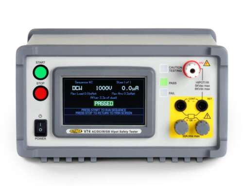
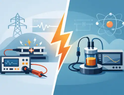
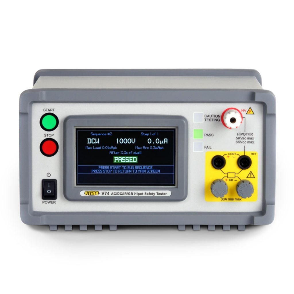
A hipot or dielectric withstand test answers an essential question: can the insulation survive a specified voltage for a defined duration without a complete breakdown? Partial discharge testing answers a different question: is the insulation system experiencing localized ionization that may drive long-term degradation?
Neither test replaces the other. Withstand testing is valuable for identifying gross insulation weaknesses and verifying safety margins. PD measurement is more sensitive to localized defects that may not cause an immediate failure. For products expected to operate for years under elevated voltage, temperature cycling, vibration, humidity, or repetitive inverter-driven waveforms, the distinction can be critical.
The severity of PD depends on more than the magnitude of an individual pulse. Engineers should consider inception voltage, extinction voltage, repetition rate, phase position, pulse pattern, operating voltage, temperature, humidity, and trend over time. A low apparent charge reading is not automatically acceptable, and a high reading does not always identify the most damaging defect without further analysis. The insulation technology, equipment design, applicable standard, and test configuration determine what constitutes meaningful risk.
PD Inception and Extinction Voltage
Two terms are central to PD characterization. Partial discharge inception voltage, or PDIV, is the lowest applied voltage at which PD becomes detectable as voltage rises under specified test conditions. Partial discharge extinction voltage, or PDEV, is the voltage at which the activity ceases as voltage is reduced.
The difference between these values can reveal useful information about the defect and dielectric system. In many cases, discharge persists below the voltage at which it began because ionization products, residual charge, and altered local conditions support continued activity. A design with PDIV comfortably above the maximum expected operating and transient voltage generally has more margin than one with inception near normal service voltage.
Test procedures must define voltage ramp rate, dwell time, frequency, coupling arrangement, background noise limit, and acceptance criteria. Without controlled conditions, comparisons between units, production lots, or test laboratories can be misleading.
How Partial Discharge Is Measured
The conventional measurement method described in IEC 60270 measures apparent charge, typically reported in picocoulombs (pC). Apparent charge is not a direct measurement of the physical charge at the defect. It is the charge that, if injected at the terminals of the test object, would produce the same measured response at the measuring system. This is an important practical distinction when comparing different equipment geometries and coupling networks.
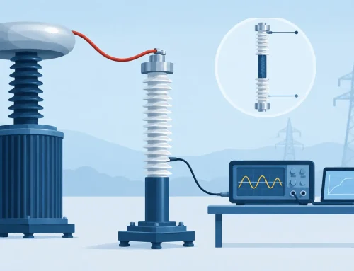
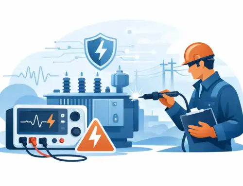
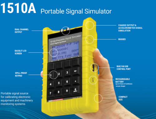
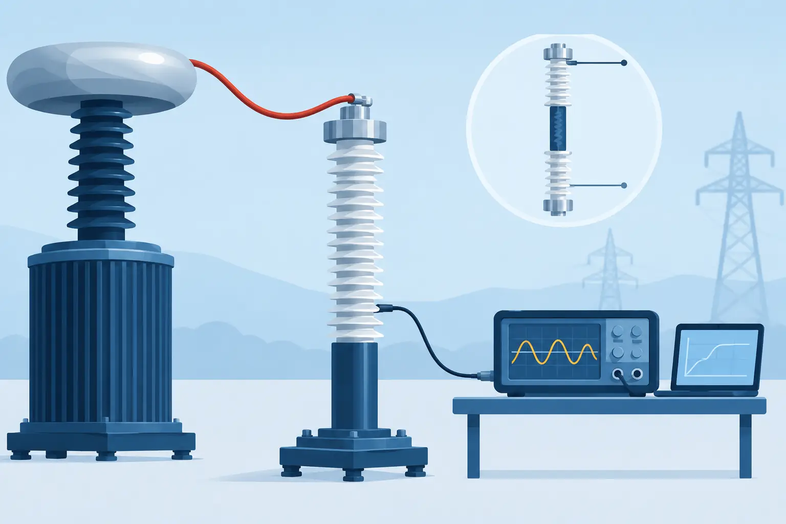
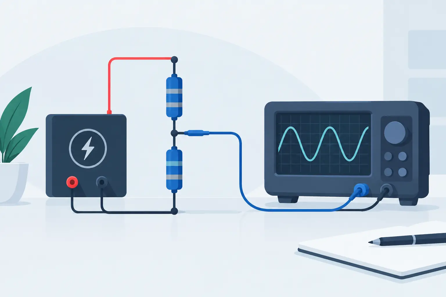
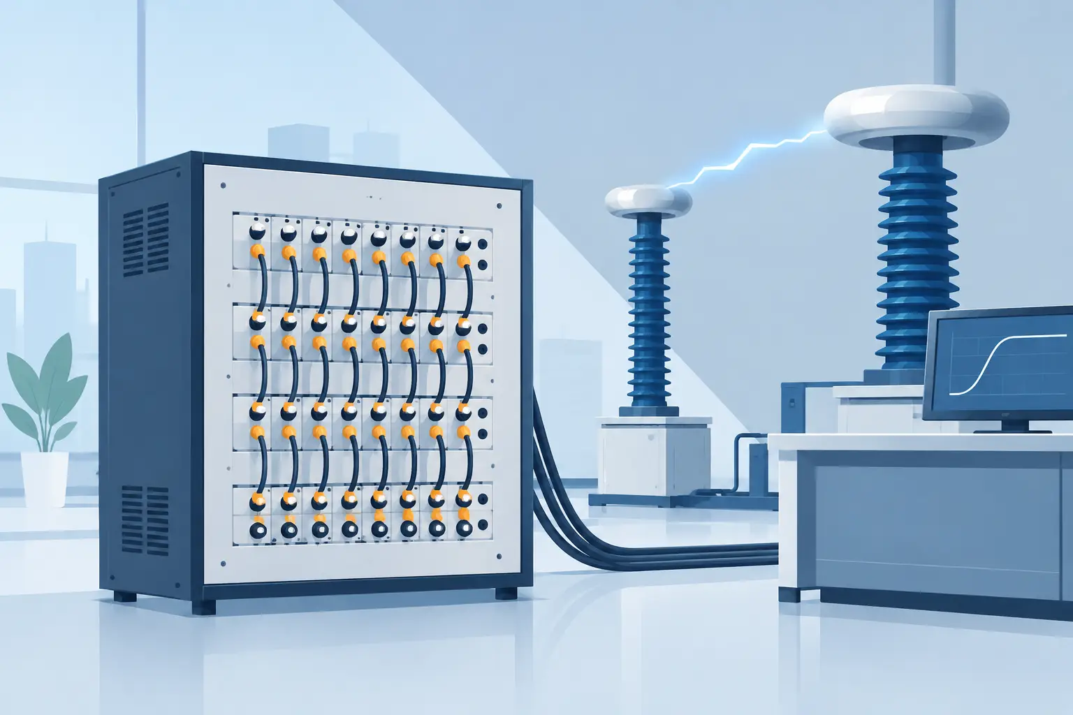
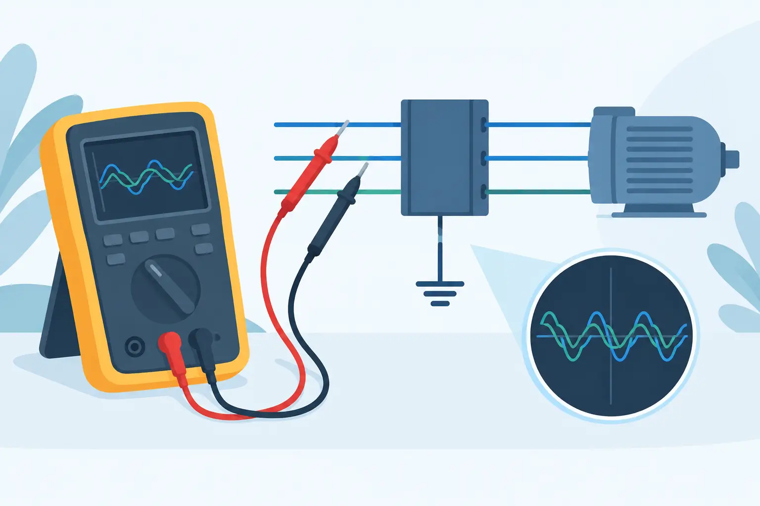
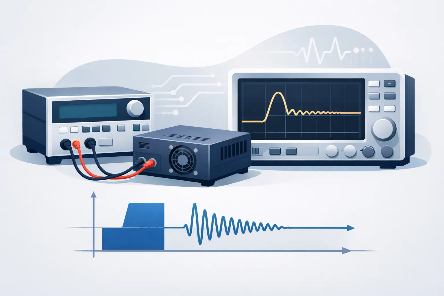
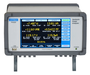
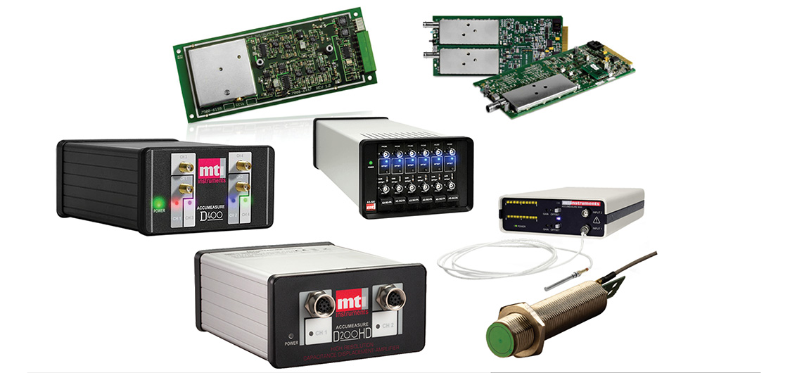
A conventional PD test system typically includes a high-voltage source, test object, coupling capacitor or coupling device, measuring impedance, acquisition instrument, and calibration source. The measurement chain must be calibrated for the specific setup. Shielding, grounding, cable routing, and separation from external interference are equally important, especially in production environments with switching power supplies, drives, relays, and radio-frequency noise.
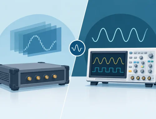
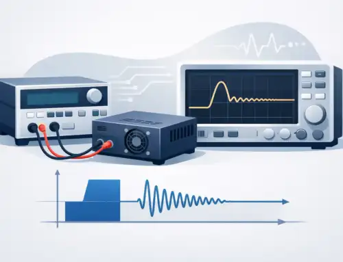
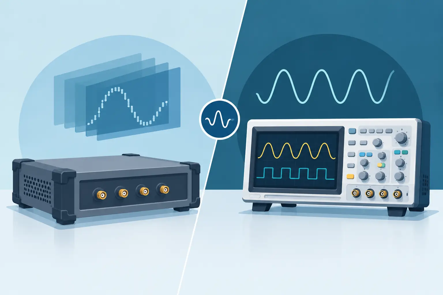
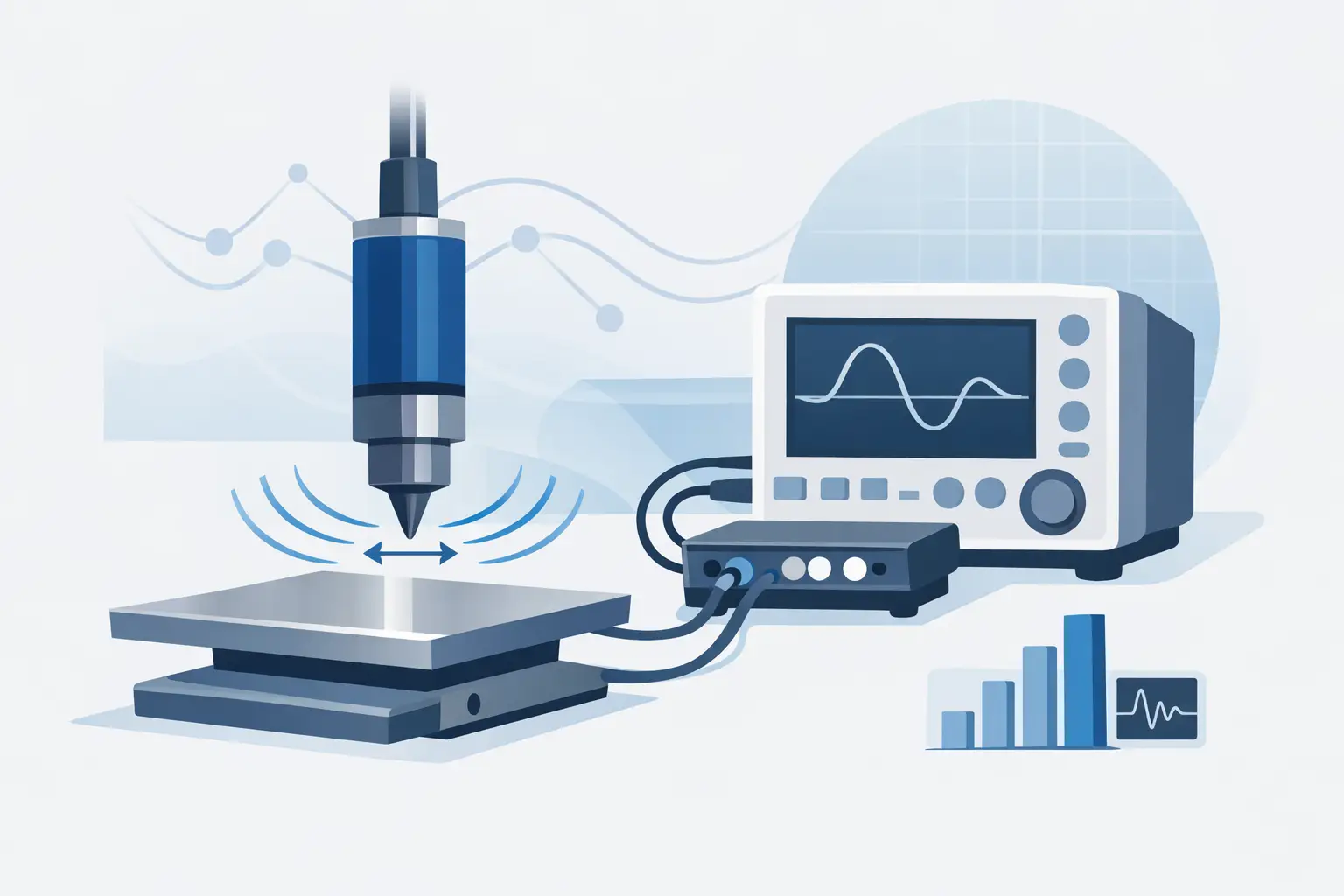
PD pulses are fast. Depending on the application, detection may also use high-frequency current transformers, ultra-high-frequency sensors, acoustic sensors, transient earth-voltage methods, or optical techniques. These nonconventional approaches are often useful for online monitoring or locating activity in installed assets. Their sensitivity, frequency response, and ability to quantify apparent charge may differ substantially from a conventional IEC 60270 measurement.
For laboratory qualification and manufacturing acceptance, conventional methods provide a well-established basis for repeatable, standards-aligned results. For field diagnostics, sensor selection often depends on asset accessibility, voltage class, noise environment, and whether the objective is detection, trending, localization, or formal acceptance testing.
Separating Real PD From Electrical Noise
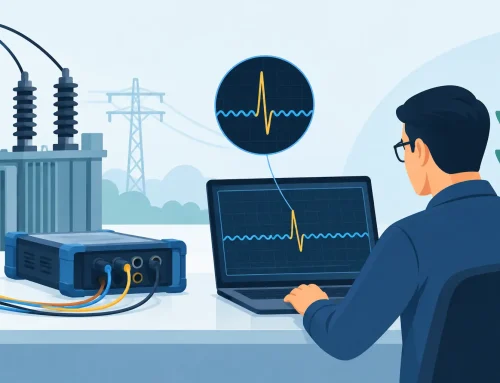
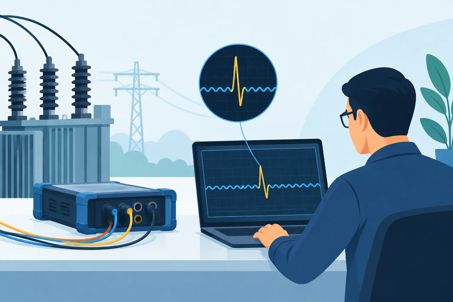
A credible PD result requires more than observing pulses on a display. External interference can resemble discharge activity. Common sources include switching transients, digital electronics, fluorescent lighting, corona from nearby fixtures, grounding faults, radio transmissions, and intermittent connections in the test setup itself.
Phase-resolved partial discharge analysis, often called PRPD, helps distinguish discharge mechanisms from noise by plotting pulse magnitude and occurrence relative to the AC voltage phase angle. Internal void discharge, surface discharge, and corona can produce different phase distributions, though interpretation requires experience and should be supported by controlled testing. Pattern recognition is useful, but it is not a substitute for understanding the insulation structure and measurement circuit.
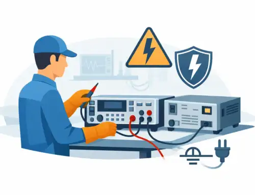
Good practice starts with a low-noise test environment and a verified ground scheme. Measure background noise before connecting the test object, establish the instrument bandwidth deliberately, perform calibration, and document the test configuration. When unexpected activity appears, isolate the source methodically rather than assuming the unit under test is defective.
Applying PD Testing in Product Development and Production
The right point to introduce PD testing depends on product risk and manufacturing maturity. During R&D, it can reveal inadequate clearances, field concentrations, material incompatibility, winding-process issues, and weaknesses that accelerated life testing may later expose. In design verification, PDIV and PDEV testing can support insulation coordination decisions and validation against application requirements.
In manufacturing, PD screening can identify process escapes such as voids in potting compounds, incomplete impregnation, damaged magnet wire, contamination, poor terminations, and assembly variation. The trade-off is cycle time and test-system complexity. A production test must be sensitive enough to identify meaningful defects while remaining resistant to normal electrical noise and practical enough to support throughput.
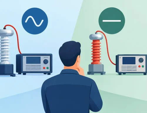
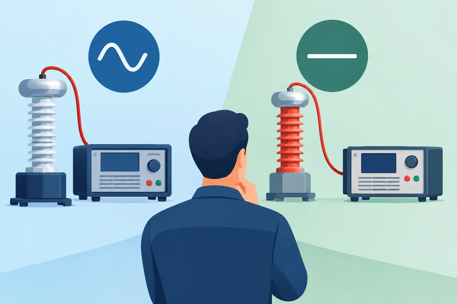
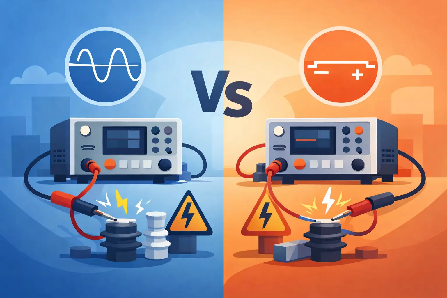
For rotating machines and power-electronics assemblies, waveform selection deserves particular attention. A 50/60 Hz sinusoidal test may be appropriate for some requirements, while fast-rise pulses from inverter switching can create different field distributions and insulation stresses. The test method should reflect the actual service environment rather than relying on a convenient voltage source alone.
Building Confidence in PD Results
Partial discharge data is most useful when it is traceable, repeatable, and connected to a defined engineering decision. That means selecting the appropriate measurement method, controlling the test environment, calibrating the system, recording the relevant settings, and establishing acceptance limits based on design risk and applicable requirements.
For high-stakes products, PD testing is not simply a pass/fail station. It is a way to see insulation behavior before that behavior becomes a field failure. A disciplined measurement strategy gives engineering and quality teams the evidence needed to improve designs, stabilize processes, and protect the service life of the equipment they build.