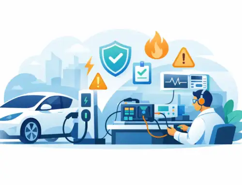
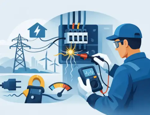
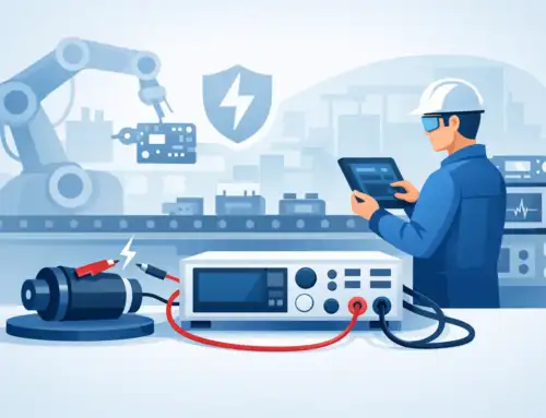
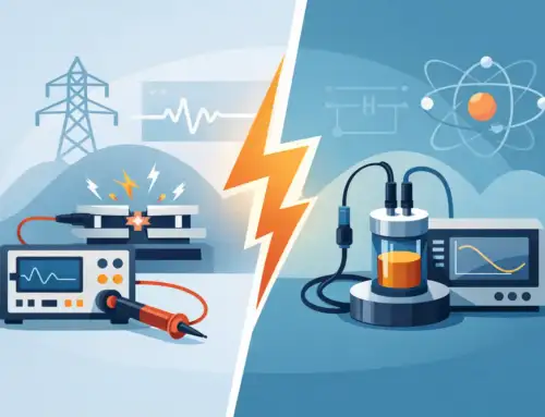
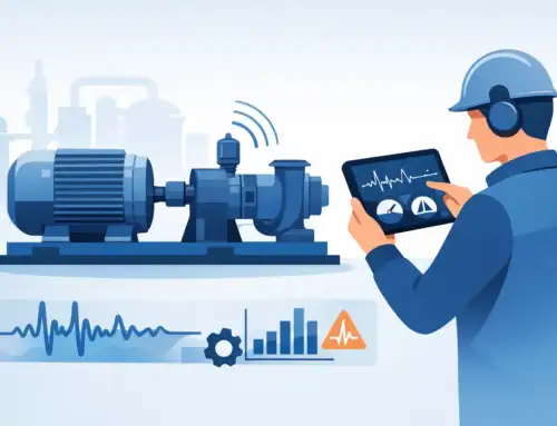
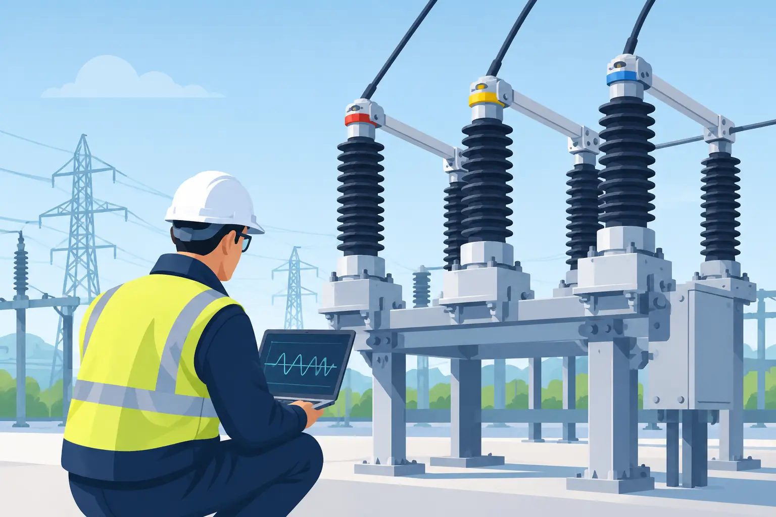
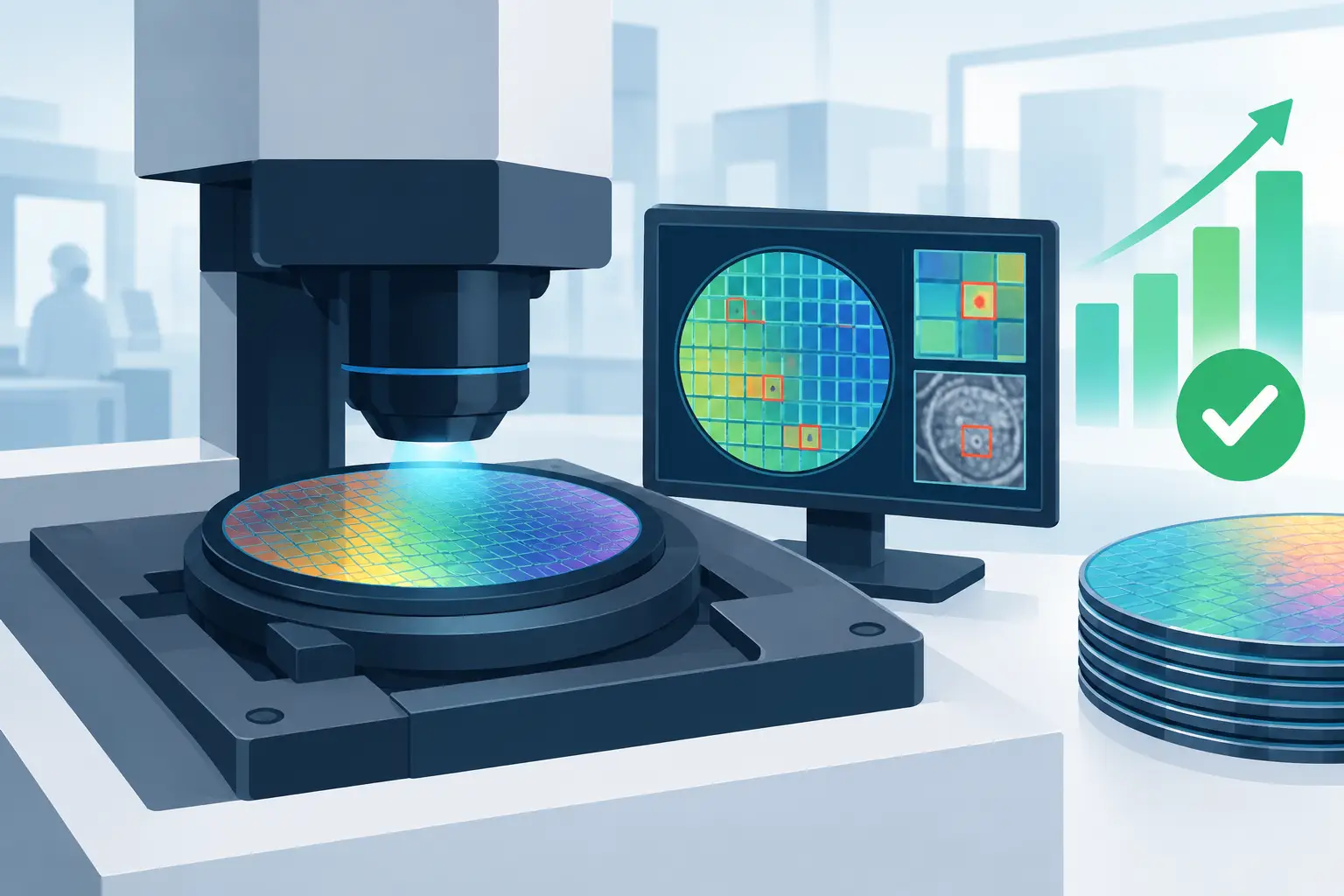
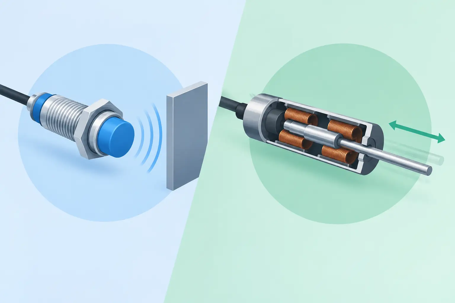
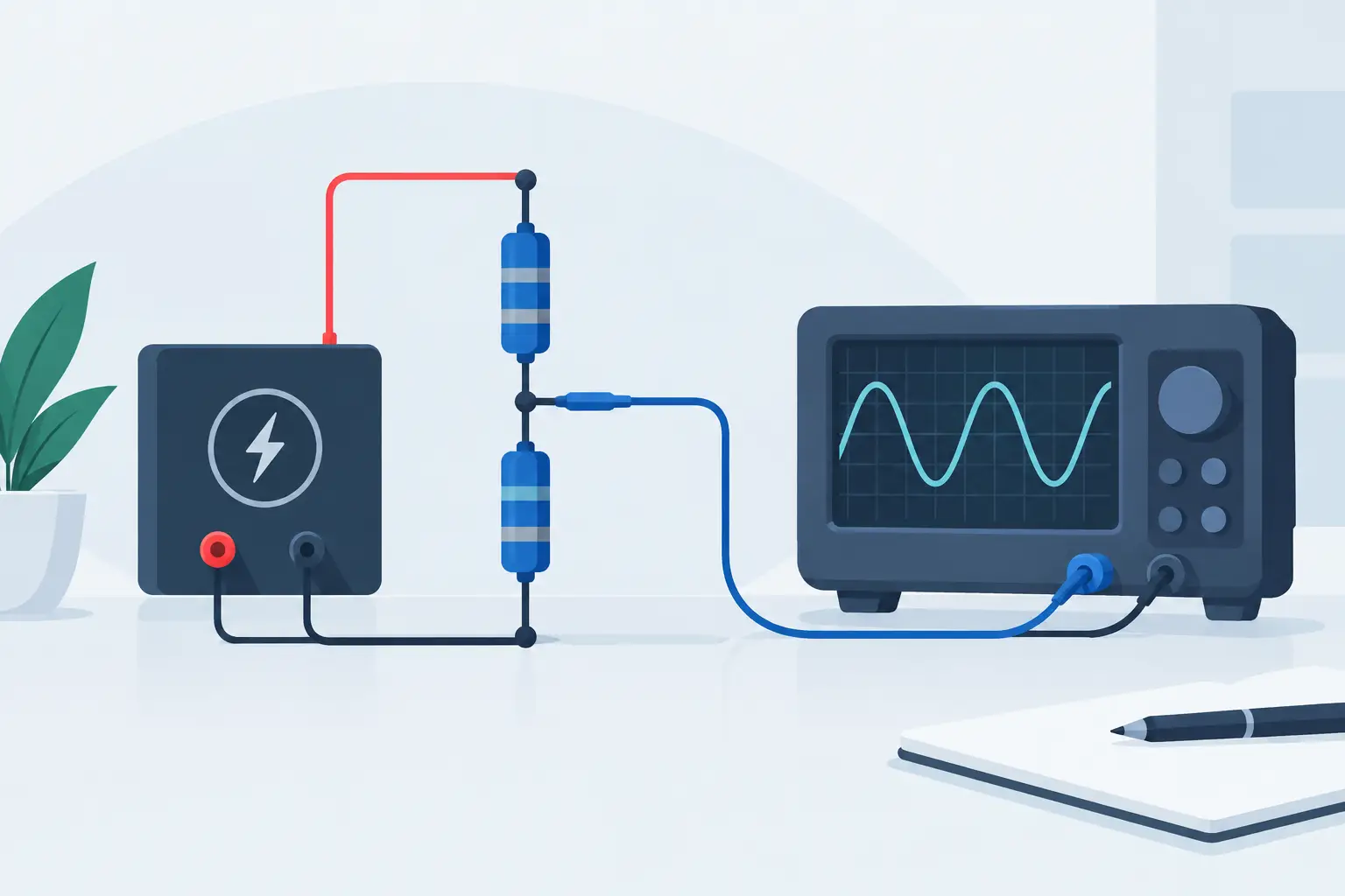
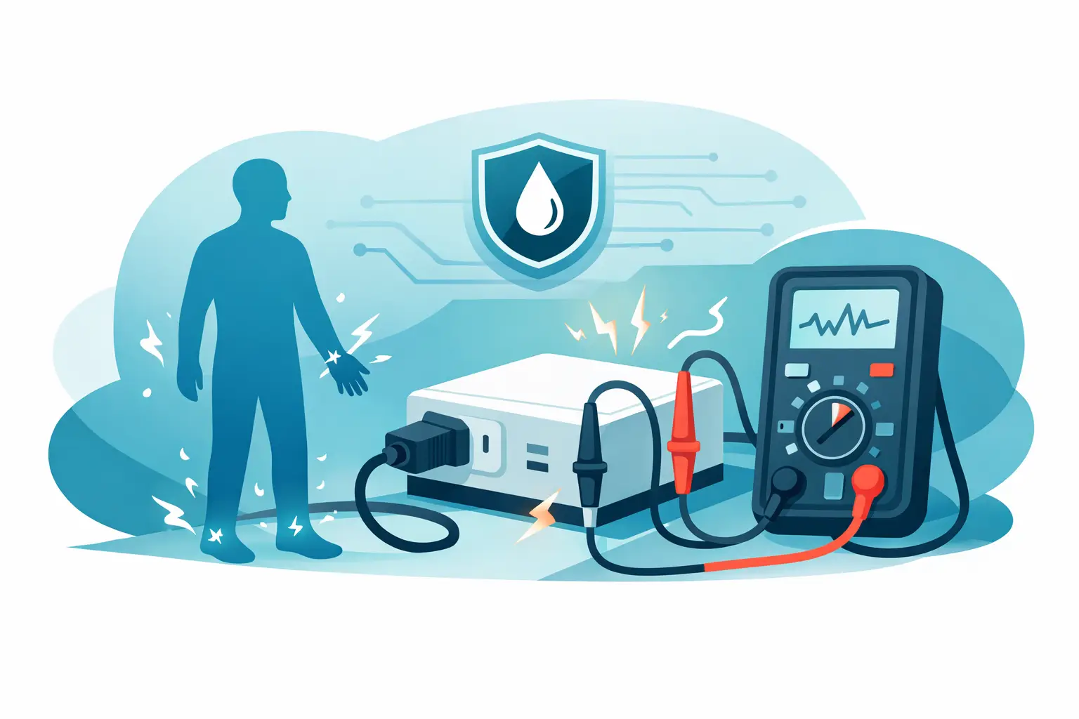
A motor that passes a startup check can still be approaching an insulation-related failure. A cable may carry rated current for years, then fail during a humidity event, switching transient, or overload. Asking why does insulation fail is not merely a materials question. It is a question of electrical stress, thermal history, contamination, mechanical condition, and the quality of the measurements used to assess degradation.
For engineering and maintenance teams, insulation failure matters because it can create shock hazards, arc events, unplanned downtime, product nonconformance, and damage to high-value equipment. The objective is not to expect insulation to remain perfect indefinitely. It is to identify degradation early enough to make a defensible maintenance, repair, or replacement decision.
Why Does Insulation Fail? It Is Usually Cumulative
Electrical insulation is designed to prevent unintended current flow between conductors, or between a conductor and ground. Its performance depends on dielectric strength, insulation resistance, physical integrity, and its ability to withstand the operating environment. Most failures develop progressively, even when the final event appears sudden.
A useful model is that insulation ages when stresses exceed, or repeatedly approach, the material’s practical limits. Heat accelerates chemical aging. Moisture lowers surface resistance and can penetrate porous materials. Mechanical motion creates cracks and abrasion. Electrical fields concentrate at voids, sharp edges, damaged terminations, and contaminated surfaces. One factor often amplifies another.
For example, a winding operating at elevated temperature may experience varnish embrittlement. Vibration can then crack the embrittled insulation, allowing moisture or conductive dust to reach the winding surface. The measured insulation resistance may decline only after those mechanisms have been active for a substantial period.
Thermal Aging and Overheating
Heat is among the most persistent causes of insulation deterioration. Sustained overtemperature exposure can oxidize polymers, drive off plasticizers, harden varnishes, and reduce flexibility. In windings, thermal cycling also produces differential expansion between conductors, insulation films, slot liners, potting compounds, and structural materials.
The source of heat is not always obvious. It may result from overload, inadequate ventilation, blocked cooling paths, high ambient temperature, poor connections, harmonic losses, repeated starts, or localized losses near a termination. A thermal issue can be highly localized, so an average temperature measurement may not reveal the most stressed area.
Temperature also affects insulation resistance test results. Comparing readings taken at significantly different temperatures without correction can produce misleading trends. A sound program records test voltage, temperature, humidity, equipment state, and test duration with every measurement.
Electrical Stress, Transients, and Partial Discharge
Insulation systems are rated for a defined voltage environment, but real systems encounter more than their nominal voltage. Switching operations, inverter-driven motors, inductive load interruption, lightning-related surges, and fast-rising voltage waveforms can apply repetitive electrical stress.
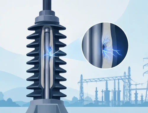
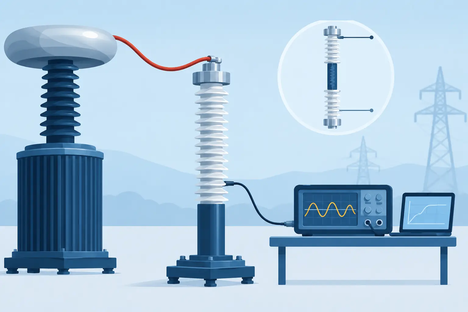
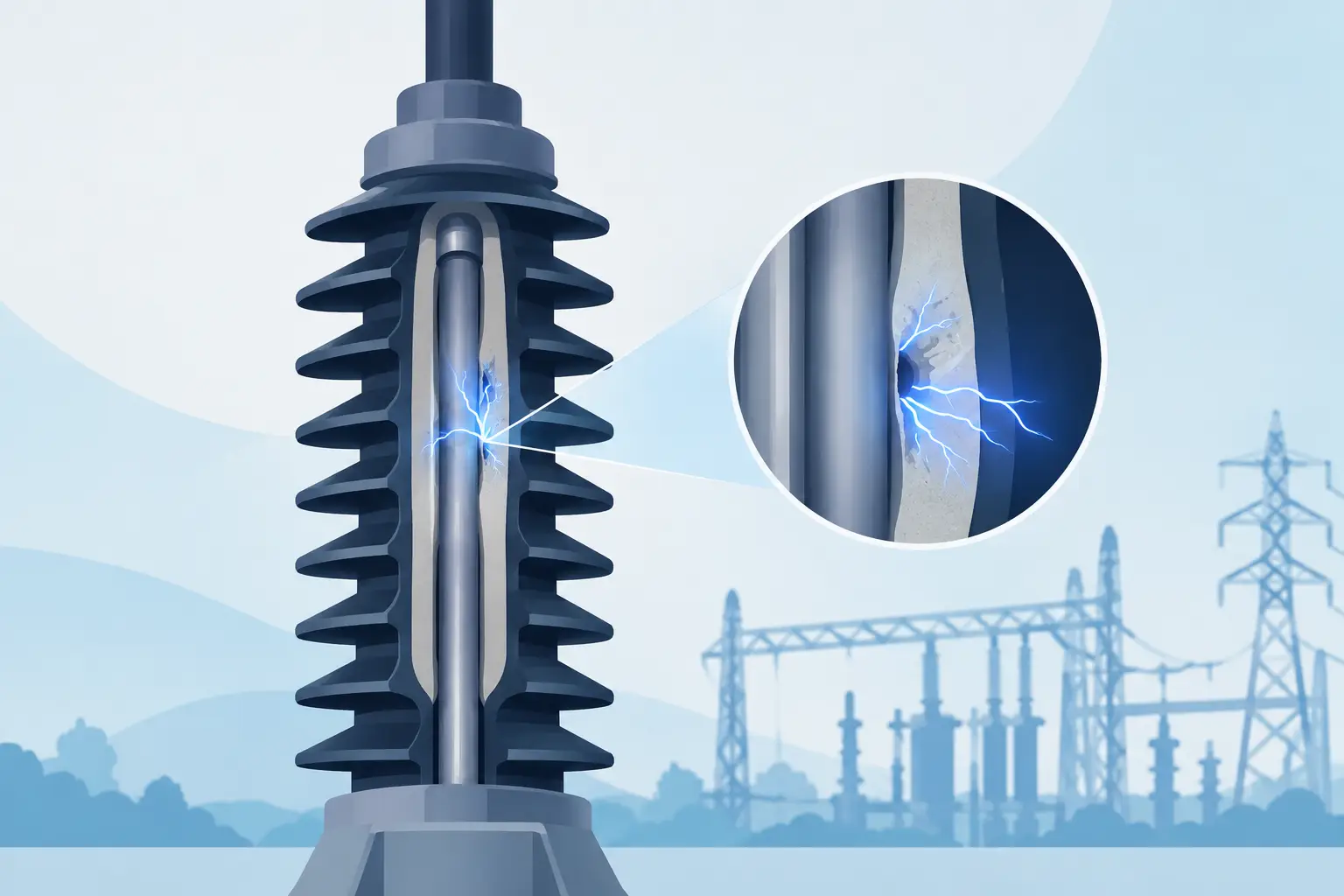
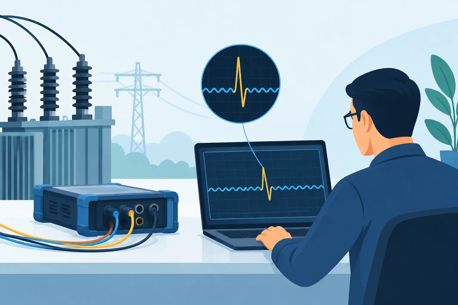
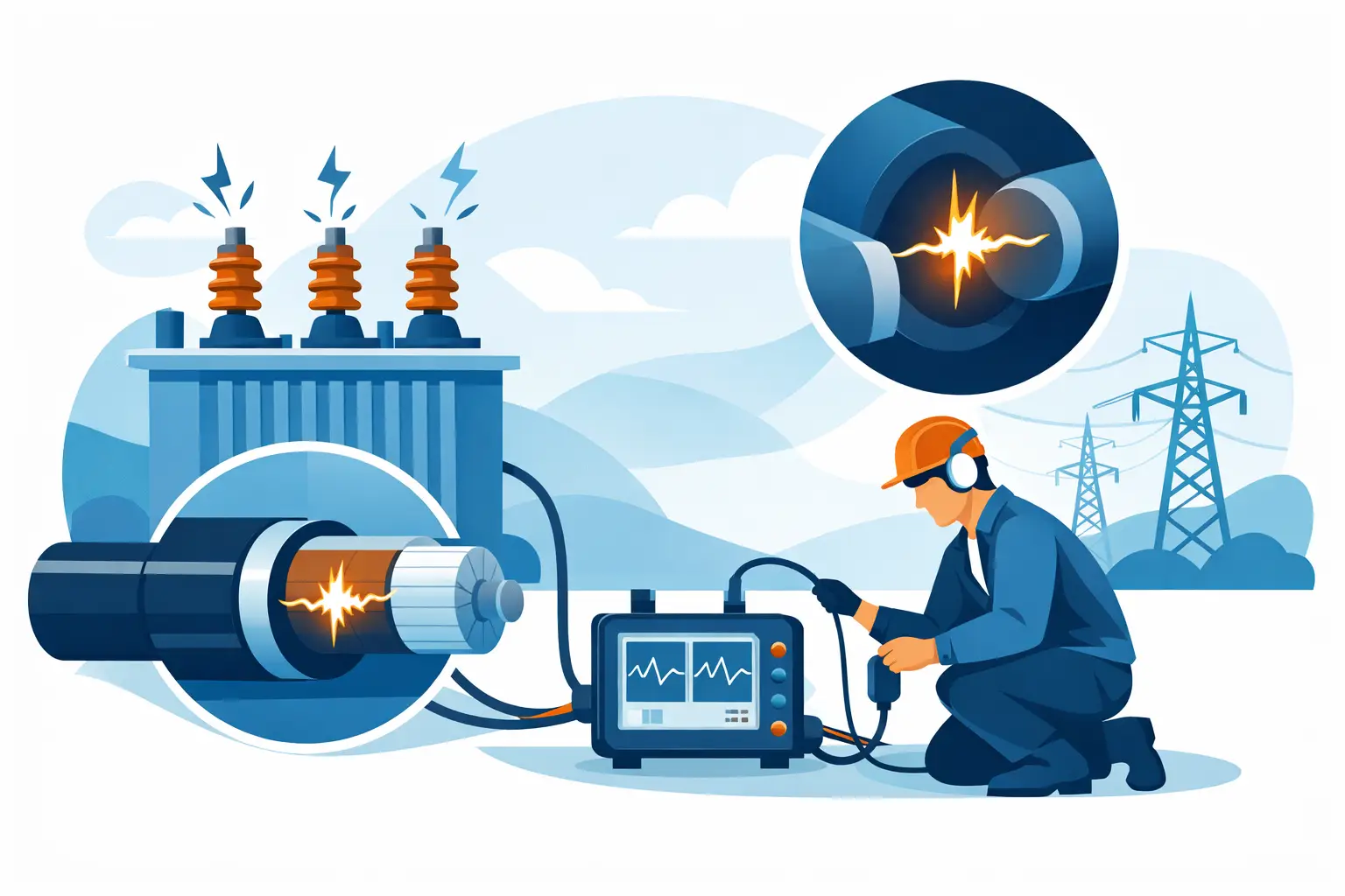
High electric-field intensity is especially damaging where geometry is unfavorable. Air voids in molded insulation, sharp conductor edges, inadequate spacing, and degraded terminations can produce localized field enhancement. In medium- and high-voltage systems, partial discharge may erode material over time without immediately creating a complete short circuit.
Electrical stress is not limited to large voltage events. Repeated lower-level stress can initiate degradation when the insulation system contains defects or operates in a contaminated, humid, or thermally aged condition. This is why a pass/fail dielectric withstand result alone does not establish long-term insulation health.
Moisture, Contamination, and Chemical Exposure
Water is a frequent contributor to insulation problems because it changes both bulk and surface conduction behavior. Condensation, washdown, flooding, inadequate enclosure sealing, and high humidity can reduce resistance and introduce leakage paths. Moisture can also transport dissolved contaminants into cracks, interfaces, and porous materials.
Contamination is often more consequential than moisture alone. Conductive dust, salts, carbon deposits, machining fluids, process residues, and corrosive chemicals create paths across insulation surfaces. In industrial settings, these conditions commonly develop near terminal blocks, cable entries, connectors, and winding end turns.
Cleaning may restore acceptable readings in some cases, but it should not be treated as proof that the underlying insulation system is sound. If contamination has caused tracking, chemical attack, or corrosion, the affected material may remain vulnerable after surface cleaning.
Mechanical Damage and Installation Defects
Insulation can fail because it was damaged before the equipment entered service. Excessive cable pulling tension, poor bend-radius control, pinched conductors, improper stripping, sharp enclosure edges, and poorly supported harnesses can initiate cuts or compression damage. These defects may not be visible after installation.
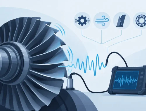
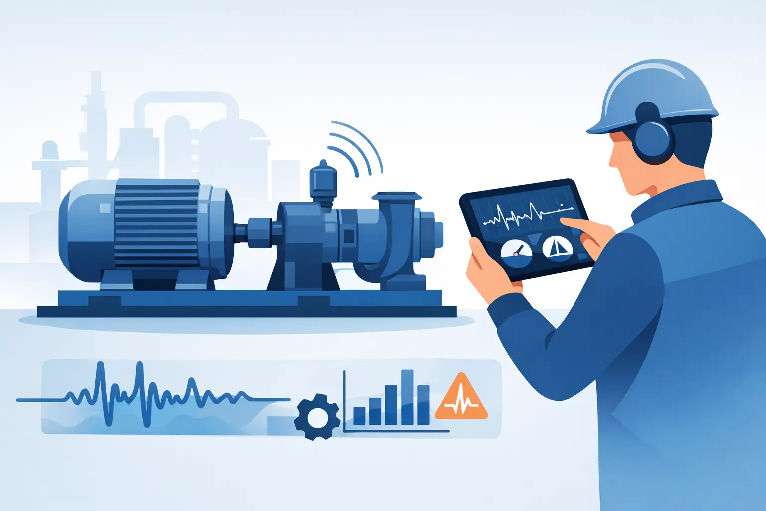
In service, vibration, abrasion, connector movement, and repeated flexing can wear through jackets and primary insulation. Rotating equipment introduces additional concerns, including winding movement, bearing-related vibration, and abrasion at leads or slot exits. Even small mechanical defects can become serious when combined with electrical stress and contamination.
Testing Must Match the Failure Mechanism
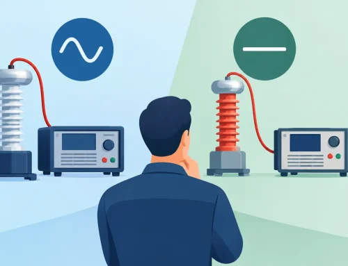
No single test explains every insulation condition. A meaningful program selects measurements based on equipment type, voltage class, material system, service environment, and the failure modes of concern.
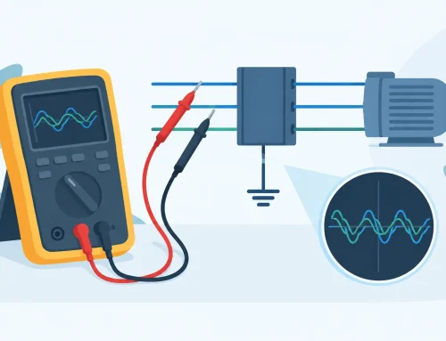
Insulation resistance testing is widely used because it can reveal leakage paths associated with moisture, contamination, and broad insulation deterioration. However, the result is dependent on test voltage, test duration, temperature, humidity, and the capacitance of the device under test. A single resistance value without test conditions has limited diagnostic value.
Time-based measurements can add useful context. In suitable applications, observing resistance as the test voltage is held can help distinguish a dry, clean insulation system from one with surface leakage or absorption characteristics that warrant investigation. Polarization index and dielectric absorption methods can be valuable, but they are not universally applicable. Modern low-capacitance insulation systems, short test windows, and certain equipment configurations can make ratio-based interpretation less meaningful.
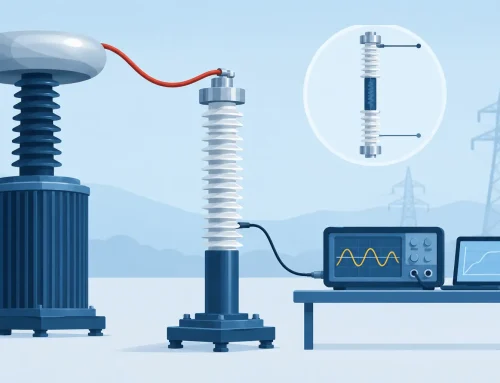
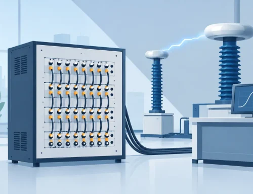
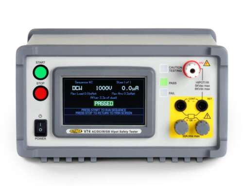
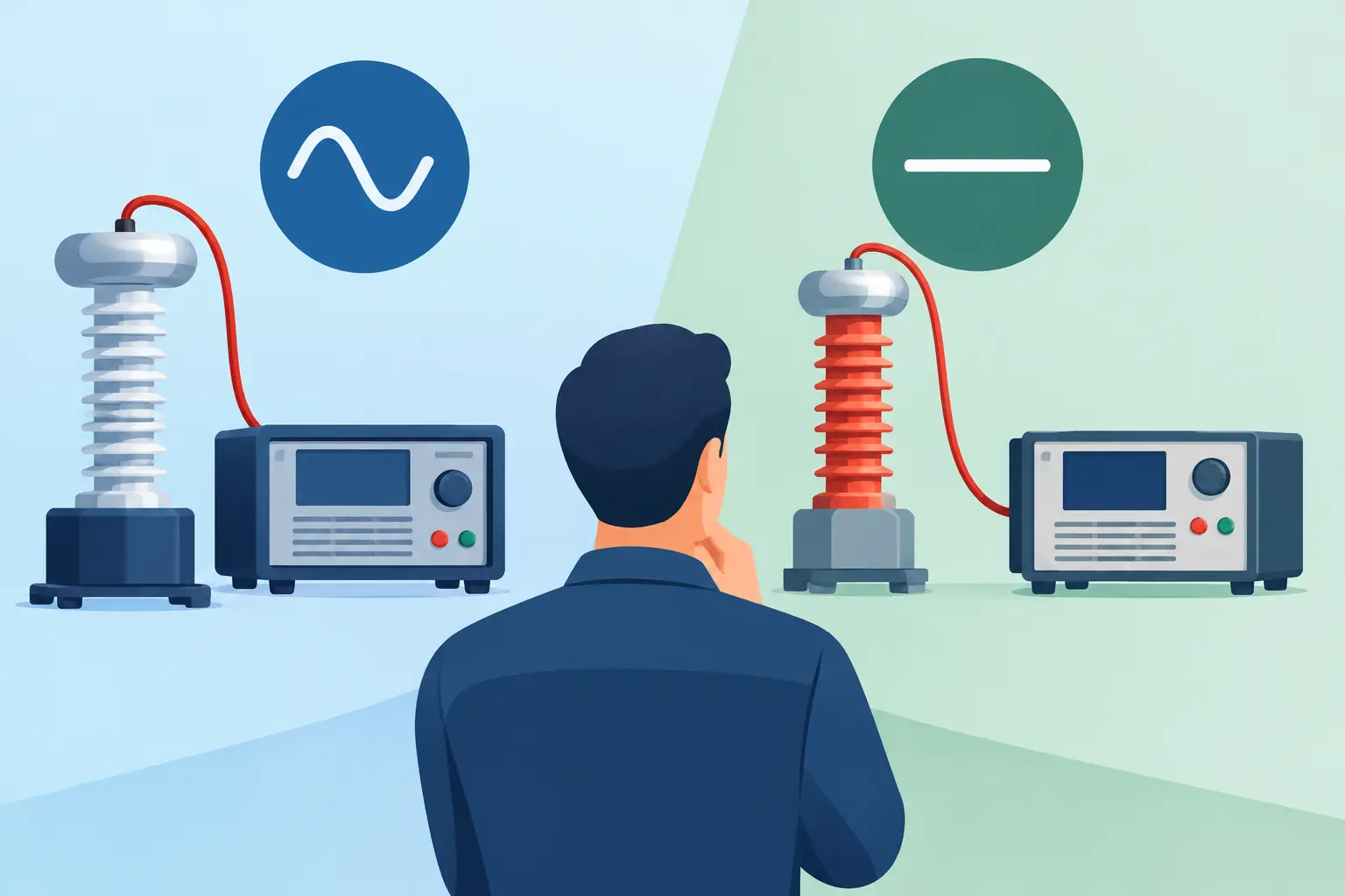
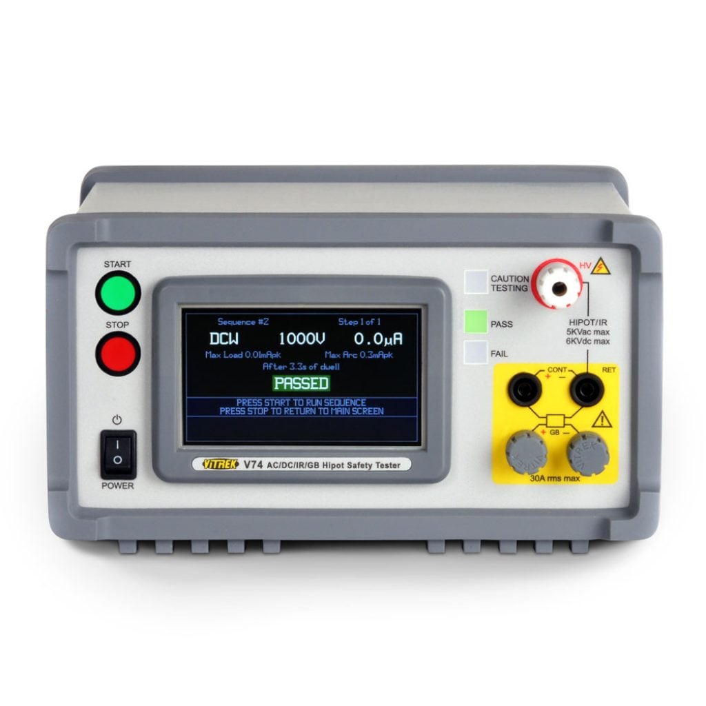
Dielectric withstand, or hipot, testing evaluates whether the insulation can tolerate a specified overvoltage for a defined duration. It is essential for many production and compliance applications, yet it is generally a qualification or screening test rather than a full condition-monitoring method. Test limits must reflect the applicable product standard, equipment design, and whether the test is performed on new production, repaired equipment, or aging field assets.
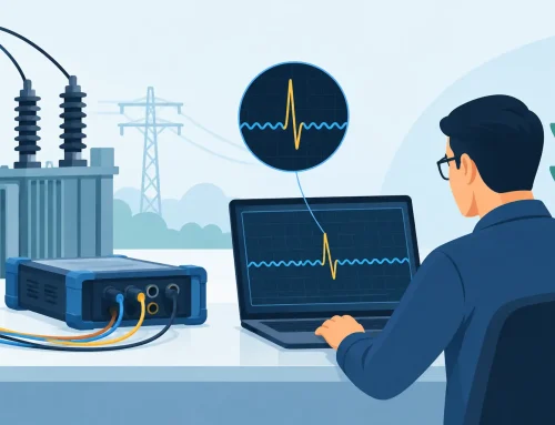
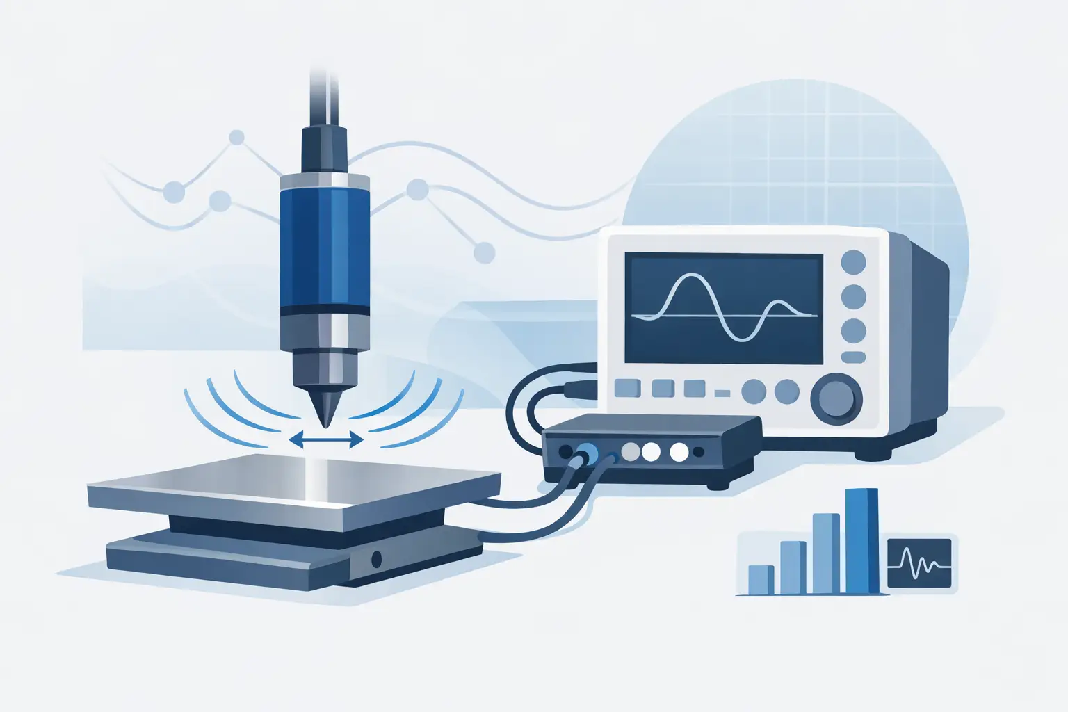
For critical assemblies, teams may also use partial-discharge measurement, leakage-current analysis, surge testing, thermal imaging, visual inspection, and controlled environmental testing. The appropriate method depends on what failure mechanism is plausible. Applying excessive test voltage or the wrong procedure can itself introduce risk, particularly on aged assets or electronics connected to the circuit under test.
Build a More Defensible Insulation Assessment
The most reliable maintenance decisions come from repeatable data, not isolated readings. Establish a documented baseline when equipment is new, after repair, or following installation. Then compare future results using the same test method and similar environmental conditions whenever practical.
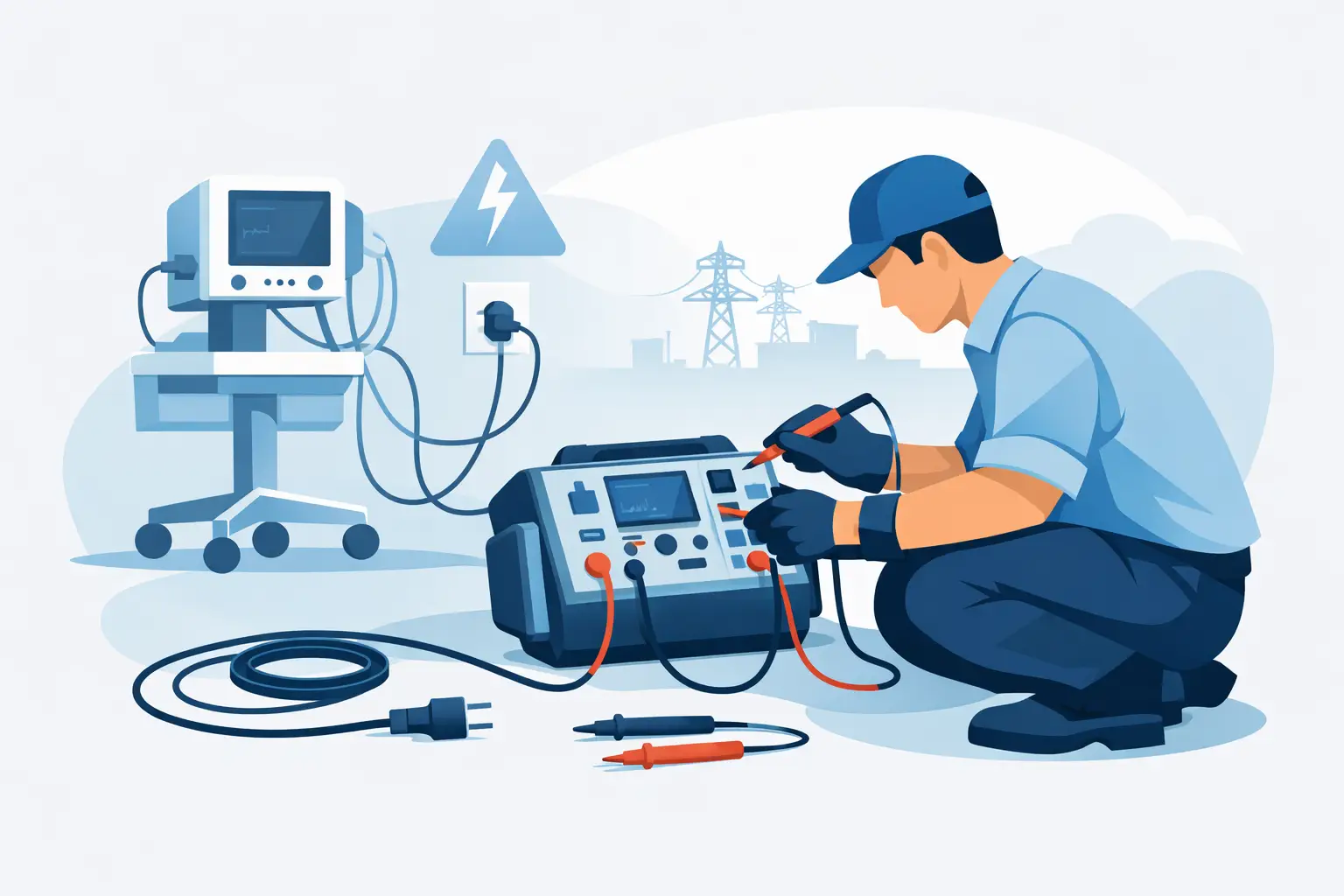
A disciplined assessment process should include four elements:
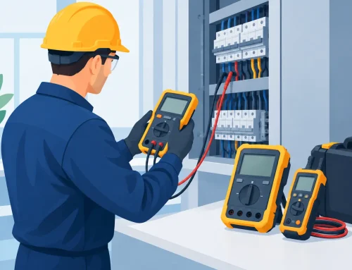
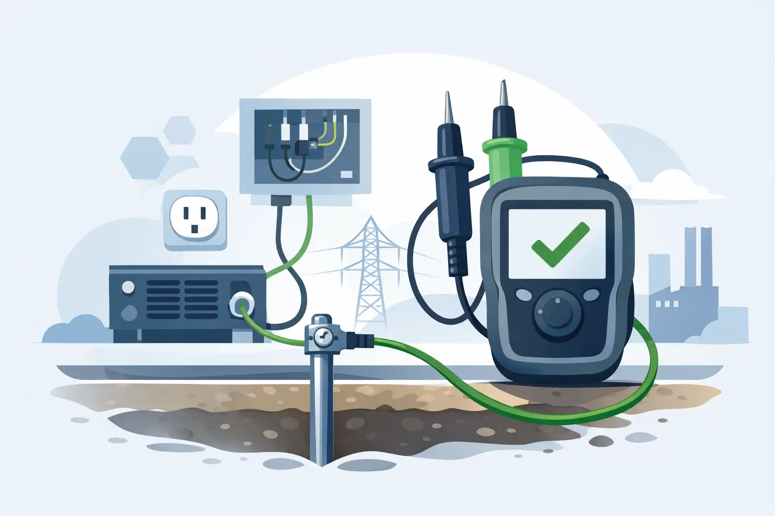
- Verify the test setup, including isolation, grounding, lead condition, test voltage, and instrument calibration status.
- Record temperature, humidity, equipment identification, test duration, and the exact configuration of the device under test.
- Trend results over time and investigate rate of change, not only whether a reading exceeds a minimum threshold.
- Correlate electrical results with operating history, visual evidence, contamination exposure, overload events, and prior repairs.
This approach prevents a common error: treating a favorable measurement as a permanent clearance. A high insulation-resistance reading can coexist with a localized defect that appears only under vibration, thermal expansion, high field stress, or a specific environmental condition. Conversely, a low reading may be caused by correctable surface moisture or contamination rather than irreversible bulk damage.
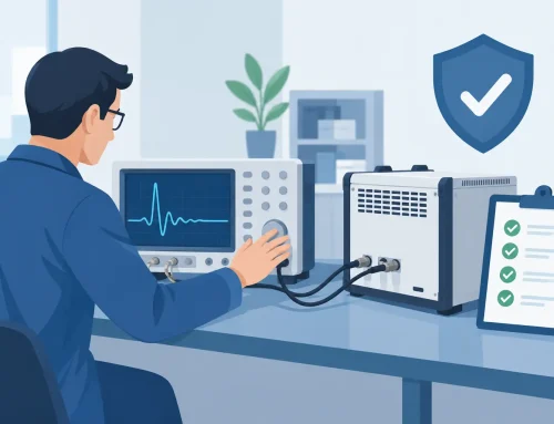
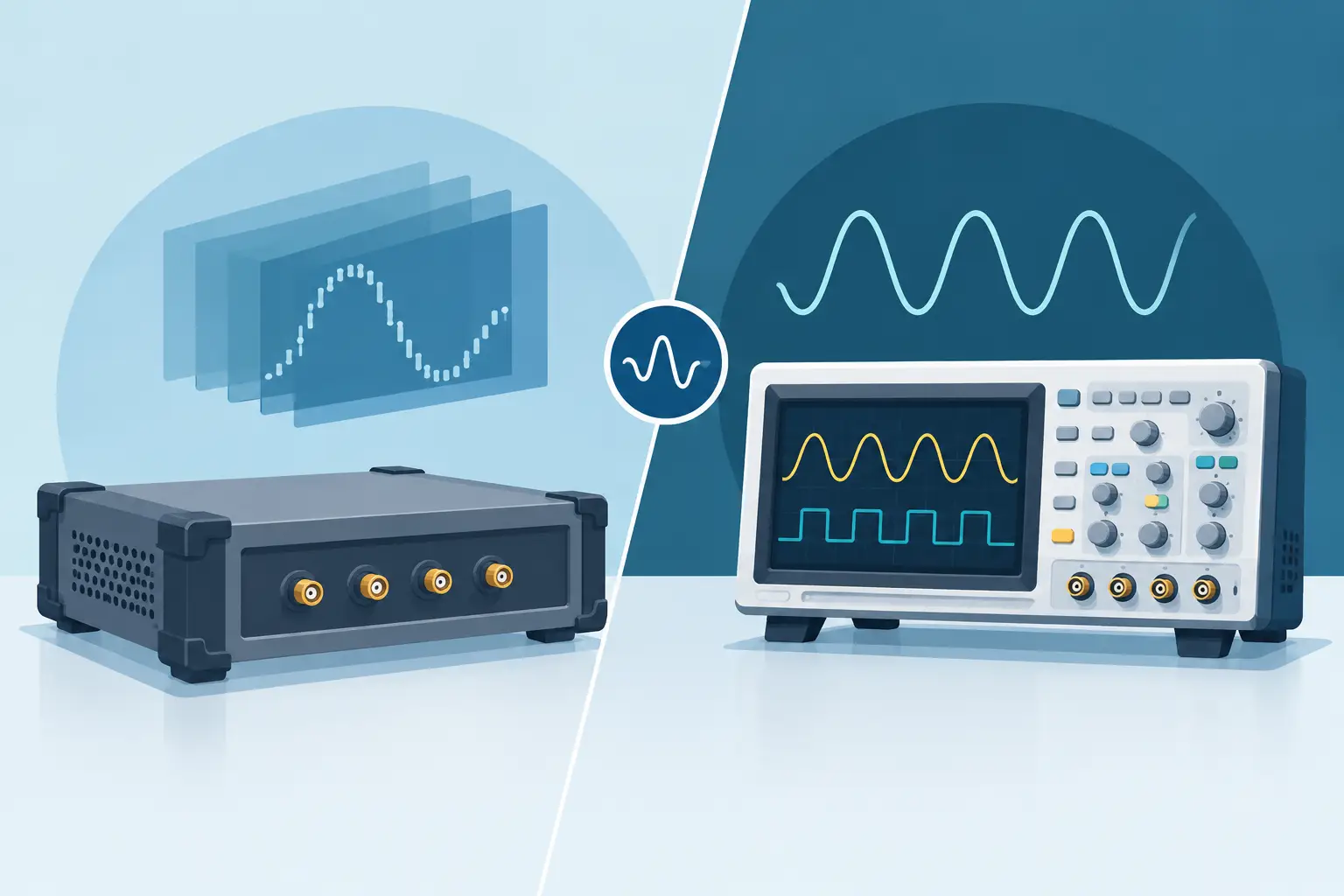
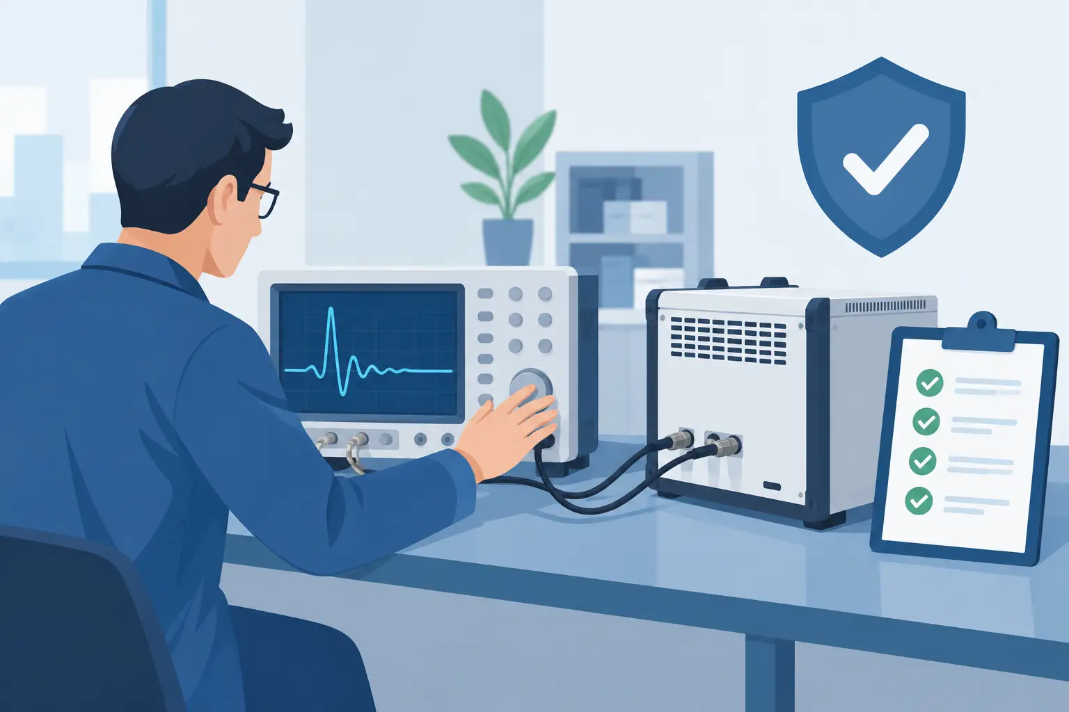
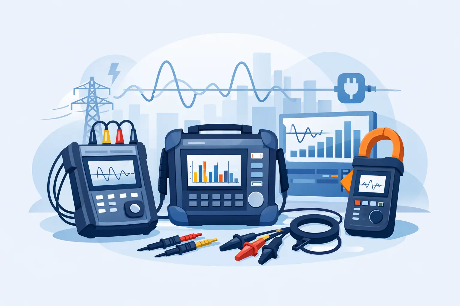
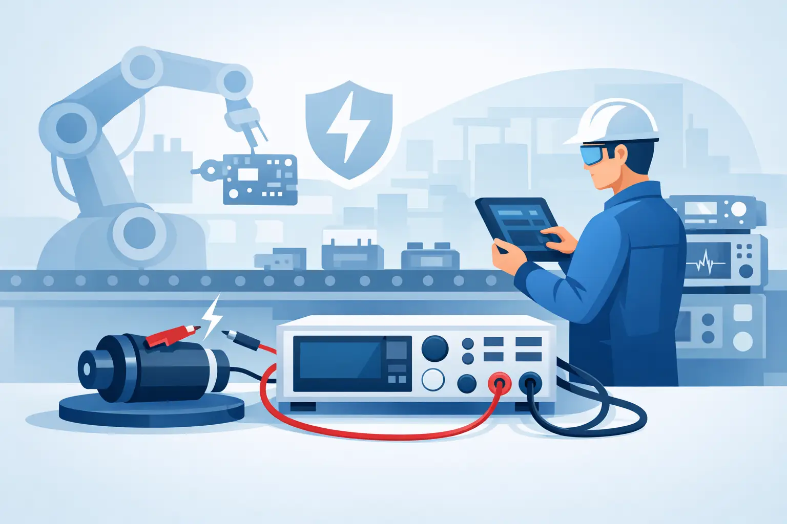
Instrumentation capability matters when decisions depend on small changes in leakage current or resistance. Test systems should provide stable programmable voltage, appropriate measurement range, repeatable timing, protective features, and data capture that supports traceability. For regulated or safety-critical work, calibration records and documented test procedures are part of the measurement result, not administrative afterthoughts.
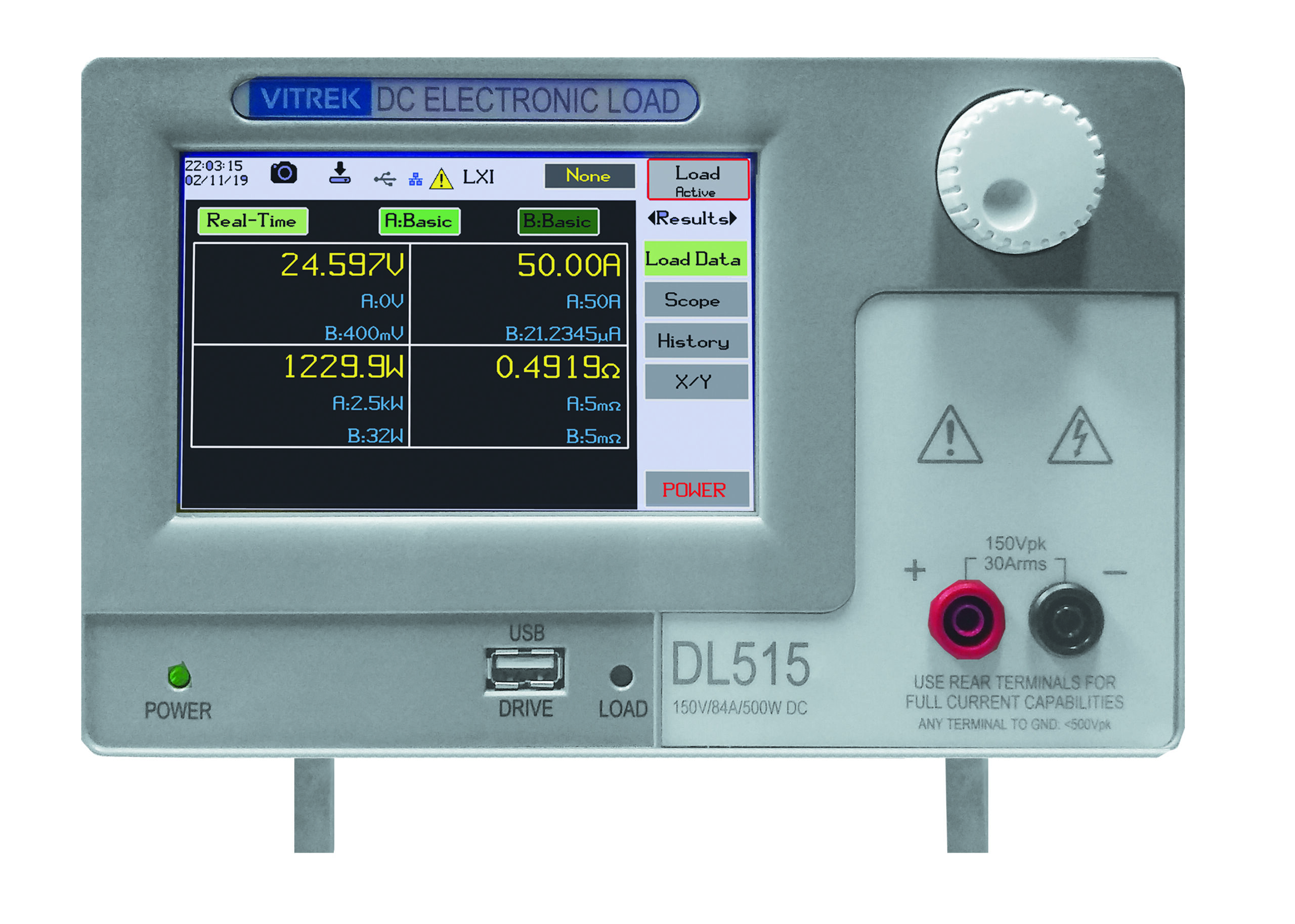
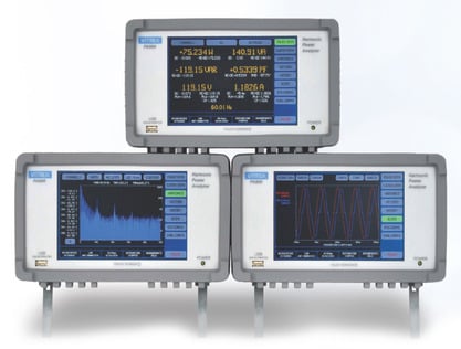
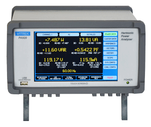
Vitrek test solutions are designed for applications where electrical safety, measurement repeatability, and documented compliance must be evaluated together. The practical requirement is to choose the method and instrument performance level that fit the asset, test standard, and risk of a false decision.
When a Low Reading Requires Investigation, Not Assumption
A low insulation-resistance result should trigger controlled troubleshooting. First confirm that the equipment is isolated and that parallel components, surge suppressors, control electronics, or measurement paths are not influencing the result. Inspect for moisture, damaged cable jackets, contamination, carbon tracking, loose terminations, and evidence of overheating.
If conditions permit, compare phases, similar units, and historical readings. A single abnormal phase or a sharp change after a process event can narrow the investigation. Drying or cleaning may be appropriate under an approved procedure, followed by retesting under documented conditions. If readings remain unstable, decline rapidly, or conflict with the equipment’s operating history, deeper diagnostic testing may be justified.
Insulation does not fail for one universal reason, and it rarely provides one universal warning. The strongest maintenance programs treat every test result as evidence within a broader operating story. When measurement conditions are controlled and trends are preserved, teams can act before insulation degradation becomes an outage, a safety event, or a costly root-cause investigation.